EP0380391A1 - Directly detachable roller, in particular for distributing fluids - Google Patents
Directly detachable roller, in particular for distributing fluids Download PDFInfo
- Publication number
- EP0380391A1 EP0380391A1 EP90400156A EP90400156A EP0380391A1 EP 0380391 A1 EP0380391 A1 EP 0380391A1 EP 90400156 A EP90400156 A EP 90400156A EP 90400156 A EP90400156 A EP 90400156A EP 0380391 A1 EP0380391 A1 EP 0380391A1
- Authority
- EP
- European Patent Office
- Prior art keywords
- roller
- roller according
- retention device
- receptacle
- shaft
- Prior art date
- Legal status (The legal status is an assumption and is not a legal conclusion. Google has not performed a legal analysis and makes no representation as to the accuracy of the status listed.)
- Withdrawn
Links
Images

Classifications
-
- A—HUMAN NECESSITIES
- A45—HAND OR TRAVELLING ARTICLES
- A45D—HAIRDRESSING OR SHAVING EQUIPMENT; EQUIPMENT FOR COSMETICS OR COSMETIC TREATMENTS, e.g. FOR MANICURING OR PEDICURING
- A45D34/00—Containers or accessories specially adapted for handling liquid toiletry or cosmetic substances, e.g. perfumes
- A45D34/04—Appliances specially adapted for applying liquid, e.g. using roller or ball
- A45D34/041—Appliances specially adapted for applying liquid, e.g. using roller or ball using a roller, a disc or a ball
Abstract
Directly detachable roller (10) having a rounded shape and having its axis of rotation equipped at at least one its ends with a device (11) which is a projection of the shaft relative to the retention device (20) of the roller and is designed so as to make the said roller easier to detach relative to its retention device (20).
Description
- The present invention relates to a detachable roller, in particular for distributors or applicators of liquids or creams.
- Numerous rollers are known. They may be fixed or detachable, and in this latter case the detachability is usually achieved by disassembling or displacing certain elements, for example attached to the shaft of the roller, and not directly.
- That is why the subject of the present invention is a roller, characterized in that it is directly detachable, has a rounded shape and has its axis of rotation equipped at at least one of its ends with a device designed so as to make the said roller easier to detach relative to its retention device.
- These rollers may be of any size but are preferably of a size such that they may be gripped axially between the thumb and index finger.
- Roller is understood to mean the roller itself and its shaft which may or may not be in one piece.
- Roller having a rounded shape is understood to mean, for example, a roller having the shape of a sphere, an ellipsoid or, preferably, a cylinder.
- Directly detachable is understood to mean that certain elements, such as pins, clips, etc., do not need to be removed to allow the detachability.
- The expression "designed so as to make the said roller easier to detach" is understood to mean that the said device makes the said detachability easier in real terms and is not a device such as a clip or pin which must be removed to allow the detachability.
- In preferred conditions of embodiments, the device designed so as to make the said roller easier to detach is a projection of the shaft relative to the retention device of the roller.
- The projection must have a length such that it juts out substantially from the retention device, for example by 2 mm or more. This projection may simply be an extension of the shaft of the roller having the same section as this shaft in the retention device, but this projection is advantageously equipped with a gripping device.
- This gripping device may, for example, be a flat surface, a rib, a butterfly nut, a spike or, preferably, a plug. This plug may be axial or radial. When it is radial, it allows the projection of the shaft to be minimized relative to the retention device ; as a result, a cap may cover the assembly with ease. These devices, in particular plugs, are themselves advantageously equipped on their outer face with contours, so as to make gripping, for example between the thumb and index finger, easier. These contours may be, for example, striations, crisscross striations, studs, etc. Conversely, these devices may have a hollow in which, for example, parts of the fingers may be placed during gripping.
- These rollers may be smooth or may, if desired, be equipped with contours, both hollow and raised, such as, in particular, studs, striations, discontinuous or otherwise, ribs, particulars or other designs.
- In certain advantageous conditions of embodiment, the roller as defined above is chararacterized in that one end of its shaft is mounted articulated about a fixed point of the retention device.
- This articulation may be of any known type, for example a ball joint, etc.
- The rollers according to the present invention may or may not have their axis of rotation integral with the roller.
- The retention device is advantageously formed by flange mountings which serve to support the two ends of the said roller. In this case, when one end of the shaft is mounted articulated, one of the flange mountings is advantageously equipped with a ball joint.
- In other preferred conditions of embodiment of the said roller, the retention device is integral with a tube serving as a cover for a receptacle and is, in particular, equipped with a device capable of being adapted to the orifice of a receptacle and has means for allowing the passage of the contents of this receptacle towards the said roller and, if desired, a device for stopping the said passage.
- A roller of this type is particularly useful in the case of an applicator of relatively viscous liquids, creams, ointments and lotions. In particular, when it is desired to be able to remove the said roller, so as to be able, for example, to clean it and/or to clean the distributor head, for example in the case of a product hardening during drying or which, upon ageing, gives rise to unpleasant smells, no contact is made with the product distributed.
- Rollers which are not, however, detachable and are fixed to application devices, are described in particular in
French Patents No 85,17605 and 82,16474, British Patent No 1,023,517 and European Patent Application No 0,150,948, the teachings of which are incorporated, by reference, in the present application. - French Patent No 85,17605, for example, describes a roller fixed in a distributor head which is formed from a tube covering a receptacle and comprising a device for retaining the roller, the distributor head and the roller being fluidly connected to a receptacle by means of an end piece resting on the neck or entering into the receptacle.
- For its part, French Patent No 74,20581 teaches, for example, receptacle stoppers to be screwed or pushed onto the neck of a bottle or a receptacle, which are furthermore equipped with a slide allowing the contents of the receptacle to be connected with the outside. A device of this kind may advantageously be combined with the stoppers equipped with the above rollers, so as to obtain applicators in which the access of the liquid to be applied using the roller may be controlled. Applicator heads of this kind equipped with the rollers of the present invention are particularly interesting since the roller may be disconnected from the distributor head, so as to clean the roller and the head, for example with running water, with no risk of spoiling the contents of the receptacle which will have been closed beforehand by the slide or another closure system which is also known.
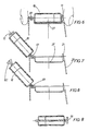
- The present invention will be better understood with reference to the attached drawings in which :
- - figure 1 is a front view of a roller ;
- - figure 2 is a sectional view showing a retention device for the said roller ;
- - figure 3 is a sectional view of the roller mounted on its retention device ;
- - figure 4 is a view from the left in accordance with the arrow IV in figure 1 of the roller ;
- - figure 5 is a view from the left in accordance with the arrow V in figure 2 of the retention device;
- - figure 6 is a lateral sectional view of a variant of the roller mounted on its retention device ;
- - figure 7 is another sectional view of the variant in figure 6 ;
- - figure 8 is a sectional view of another variant ; and
- - figure 9 is a sectional view of a roller mounted on its shaft.
- Reference will be made first to figure 1. A
roller 10 according to the invention is equipped at the end of its axis of rotation along A-A′ withradial plugs 11 and is provided withstuds 12. - Figure 2 shows the
retention device 20 of the said roller which haslateral flange mountings 21 equipped withorifices 22 which serve as the axis of rotation for the said roller. Thetube 23 is integral with areceptacle 24 by means ofcatch elements 25 which fasten in a complementary manner into thecatch parts 26 of thereceptacle 24. The contents of the receptacle may be connected with the roller by anorifice 27 provided in the end piece. - The connection between the inside of the receptacle and the
said orifice 27 is not shown in this figure. - As mentioned above, a connecting device is described, for example, in French Patents No 85,17605, British Patent No 1,023,517 or European Patent Application No 0,150,948, which connection may, for example, be interrupted by a stopping means such as that described in French Patent No 74,20581.
- Figure 3 shows the roller installed on its retention device and illustrates the ease with which it is possible to install or to lift off the said roller without contact with the product deposited on the surface of the roller. A device for connecting the
receptacle 24 with the outside by means of anorifice 27 is also shown in this figure. - As mentioned, this device may be completed with a stopper of the
orifice 27. - Figure 4 shows the striations appearing as a contour on the
plugs 11 so as to make gripping easier. - Figure 5 illustrates an exemplary retention device of one of the ends of the axis of the cylinder. The V-shape of the entry orifice of the vertical recess, which is self-locking as a result of the
lateral flange mountings 21 being produced from an elastic material, in particular a plastic material, makes the roller easier to install. - Figure 6 shows another variant embodiment in which the
roller 10, still integral with its shaft, has not been entirely removed but may be so if desired. In this illustration, one of the ends of the shaft is mounted on aball joint 61 which is fitted into the retention device. - Figure 7 shows the roller in the open position, ready, for example, for cleaning of the retention device or of the roller itself.
- Figure 8 illustrates a variant according to which the
roller 81 may be disconnected even more easily from the shaft of the roller, so as to make the latter entirely independent. Arib 82, which may, for example, be gripped between the thumb and the index finger allows the roller to pivot so as to snap-release the part opposite the ball joint from the lateral flange mounting, and the roller then to be withdrawn from the ball joint by simple translational movement. - Figure 9 illustrates a variant in which the shaft and the roller are not integral with each other and the said roller may therefore be removed by sliding. A plug 91 also forms a part of the axis of rotation, this plug is itself detachable so as to allow the translational movement of the roller.
- In the above description, the ball joint can, of course, be replaced by a body with a cylindrical shape which pivots in a suitable cylindrical housing of the lateral flange mounting 21.
- The rollers according to the present invention may be produced from any conventional materials, in particular plastic and metal materials of variable quality depending on the stresses to which the roller and its retention device are subjected.
- It is very evident that the illustrations above will in no way limit the present application and are only presented purely by way of explanation.
Claims (13)
1. Roller, characterized in that it is directly detachable, has a rounded shape and has its axis of rotation equipped at at least one of its ends with a device which is a projection of the shaft relative to the retention device of the roller and is designed so as to make the said roller easier to detach relative to its retention device.
2. Roller according to claim 1, characterized in that the projection is equipped with a gripping device.
3. Roller according to one of claims 1 or 2, characterized in that one end of the shaft is mounted articulated about a fixed point of the retention device.
4. Roller according to any one of claims 1 to 3, characterized in that the axis of rotation is integral with the roller.
5. Roller according to any one of claims 1 to 4, characterized in that the retention device is formed by flange mountings which serve to support the two ends of the roller.
6. Roller according to claim 3 or 5, characterized in that one of the flange mountings is equipped with a ball joint.
7. Roller according to any one of claims 1 to 6, characterized in that the retention device is integral with a tube which serves as a cover for a receptacle.
8. Roller according to claim 7, characterized in that the tube is equipped with a device capable of being adapted to the orifice of a receptacle and has means for allowing the passage of the contents of this receptacle towards the said roller and, if desired, for stopping the said passage.
9. Roller according to any one of claims 1 to 8, characterized in that the device designed so as to make the said roller easier to detach relative to its retention device is a plug.
10. Roller according to claim 9, characterized in that the plug is axial.
11. Roller according to claim 9 or 10, characterized in that the plug is equipped on its outer face with contours.
12. Roller according to any one of claims 1 to 11, characterized in that the roller itself is equipped with raised contours.
13. Roller according to claim 12, characterized in that the raised contours have a particular design preferably in a form of a V.
Applications Claiming Priority (2)
| Application Number | Priority Date | Filing Date | Title |
|---|---|---|---|
| FR8900817A FR2641991B1 (en) | 1989-01-24 | 1989-01-24 | DIRECTLY REMOVABLE ROLLER, PARTICULARLY FOR DISPENSING FLUIDS |
| FR8900817 | 1989-01-24 |
Publications (1)
| Publication Number | Publication Date |
|---|---|
| EP0380391A1 true EP0380391A1 (en) | 1990-08-01 |
Family
ID=9378023
Family Applications (1)
| Application Number | Title | Priority Date | Filing Date |
|---|---|---|---|
| EP90400156A Withdrawn EP0380391A1 (en) | 1989-01-24 | 1990-01-19 | Directly detachable roller, in particular for distributing fluids |
Country Status (3)
| Country | Link |
|---|---|
| EP (1) | EP0380391A1 (en) |
| AU (1) | AU626973B2 (en) |
| FR (1) | FR2641991B1 (en) |
Cited By (7)
| Publication number | Priority date | Publication date | Assignee | Title |
|---|---|---|---|---|
| EP0629366A1 (en) * | 1993-06-14 | 1994-12-21 | Seb S.A. | Applicator for hot-melt products, in particular depilatory wax, with a roller made of two materials |
| FR2720237A1 (en) * | 1993-06-14 | 1995-12-01 | Seb Sa | Applicator for depilatory wax |
| EP0779044A1 (en) * | 1995-12-14 | 1997-06-18 | Magic Dreams Cosmetica Infantil, S.L. | Improved massage-like application device for a fluid product on the skin |
| ES2133207A1 (en) * | 1996-01-23 | 1999-09-01 | Nugar Bobinajes Sl | Heated roller device for applying depilatory substances and the like |
| WO2010076912A1 (en) * | 2008-12-29 | 2010-07-08 | (주)톨리코리아 | Double cosmetics roller container including airless pump |
| JP2012210959A (en) * | 2011-03-31 | 2012-11-01 | Yoshino Kogyosho Co Ltd | Coating container |
| CN104983172A (en) * | 2015-06-23 | 2015-10-21 | 浙江百特电器有限公司 | Skin and nail grinding device |
Citations (6)
| Publication number | Priority date | Publication date | Assignee | Title |
|---|---|---|---|---|
| US2229707A (en) * | 1939-07-03 | 1941-01-28 | Gillette Safety Razor Co | Dispensing tube |
| US2892202A (en) * | 1957-12-03 | 1959-06-30 | Williams Edward | Roll-on applicator |
| US3048880A (en) * | 1960-04-14 | 1962-08-14 | Ira I Slomon | Self-starter adhesive and glue applicator |
| GB1193351A (en) * | 1967-07-03 | 1970-05-28 | Colin John Incledon Veitch | An Instrument for inscribing a Repeating Design on Paper, Wood, Plastic and other Surfaces |
| EP0150948A2 (en) * | 1984-01-13 | 1985-08-07 | Louis Marcel Limited | Improvements in the application of depilatory materials |
| US4555196A (en) * | 1983-05-02 | 1985-11-26 | Garmo Billy B De | Tanning wand |
Family Cites Families (1)
| Publication number | Priority date | Publication date | Assignee | Title |
|---|---|---|---|---|
| US4752148A (en) * | 1984-11-29 | 1988-06-21 | Inverness Corporation | Depilatory dispenser |
-
1989
- 1989-01-24 FR FR8900817A patent/FR2641991B1/en not_active Expired - Lifetime
-
1990
- 1990-01-18 AU AU48560/90A patent/AU626973B2/en not_active Ceased
- 1990-01-19 EP EP90400156A patent/EP0380391A1/en not_active Withdrawn
Patent Citations (6)
| Publication number | Priority date | Publication date | Assignee | Title |
|---|---|---|---|---|
| US2229707A (en) * | 1939-07-03 | 1941-01-28 | Gillette Safety Razor Co | Dispensing tube |
| US2892202A (en) * | 1957-12-03 | 1959-06-30 | Williams Edward | Roll-on applicator |
| US3048880A (en) * | 1960-04-14 | 1962-08-14 | Ira I Slomon | Self-starter adhesive and glue applicator |
| GB1193351A (en) * | 1967-07-03 | 1970-05-28 | Colin John Incledon Veitch | An Instrument for inscribing a Repeating Design on Paper, Wood, Plastic and other Surfaces |
| US4555196A (en) * | 1983-05-02 | 1985-11-26 | Garmo Billy B De | Tanning wand |
| EP0150948A2 (en) * | 1984-01-13 | 1985-08-07 | Louis Marcel Limited | Improvements in the application of depilatory materials |
Cited By (15)
| Publication number | Priority date | Publication date | Assignee | Title |
|---|---|---|---|---|
| US5681388A (en) * | 1993-06-14 | 1997-10-28 | Seb S.A. | Applicator for meltable products, in particular depilatory wax |
| EP0629366A1 (en) * | 1993-06-14 | 1994-12-21 | Seb S.A. | Applicator for hot-melt products, in particular depilatory wax, with a roller made of two materials |
| FR2720237A1 (en) * | 1993-06-14 | 1995-12-01 | Seb Sa | Applicator for depilatory wax |
| US5556468A (en) * | 1993-06-14 | 1996-09-17 | Seb S.A. | Applicator for meltable products, in particular depilatory wax |
| EP0784948A3 (en) * | 1993-06-14 | 1999-08-11 | Seb S.A. | Depilatory wax applicator with a retractable roller |
| EP0784948A2 (en) * | 1993-06-14 | 1997-07-23 | Seb S.A. | Depilatory wax applicator with a retractable roller |
| FR2706261A1 (en) * | 1993-06-14 | 1994-12-23 | Seb Sa | Applicator for hot-melt products, in particular for depilatory wax, comprising a dual-material application roller. |
| US5846326A (en) * | 1993-06-14 | 1998-12-08 | Seb S.A. | Applicator for meltable products in particular depilatory wax |
| EP0779044A1 (en) * | 1995-12-14 | 1997-06-18 | Magic Dreams Cosmetica Infantil, S.L. | Improved massage-like application device for a fluid product on the skin |
| ES2117938A1 (en) * | 1995-12-14 | 1998-08-16 | Magic Dreams Cosmetica Infanti | Improved massage-like application device for a fluid product on the skin |
| ES2133207A1 (en) * | 1996-01-23 | 1999-09-01 | Nugar Bobinajes Sl | Heated roller device for applying depilatory substances and the like |
| WO2010076912A1 (en) * | 2008-12-29 | 2010-07-08 | (주)톨리코리아 | Double cosmetics roller container including airless pump |
| JP2012210959A (en) * | 2011-03-31 | 2012-11-01 | Yoshino Kogyosho Co Ltd | Coating container |
| CN104983172A (en) * | 2015-06-23 | 2015-10-21 | 浙江百特电器有限公司 | Skin and nail grinding device |
| CN104983172B (en) * | 2015-06-23 | 2018-10-26 | 浙江百特电器有限公司 | Grind skin Nail clipper |
Also Published As
| Publication number | Publication date |
|---|---|
| FR2641991B1 (en) | 1991-06-07 |
| FR2641991A1 (en) | 1990-07-27 |
| AU626973B2 (en) | 1992-08-13 |
| AU4856090A (en) | 1990-08-02 |
Similar Documents
| Publication | Publication Date | Title |
|---|---|---|
| US4609300A (en) | Adjustable wiper for fluid product | |
| US5137387A (en) | Cosmetic applicator with rotary wiping system | |
| EP0408686B1 (en) | Dual cosmetic applicator and container and method for applying cosmetic | |
| US4796647A (en) | Applicator unit for a liquid, pasty or pulverulent product | |
| US4909265A (en) | Device for the application of a product to a surface, for example, an applicator device for a cosmetic product, in particular a depilatory | |
| US7114871B2 (en) | Packaging and application device for a product, notably a nail varnish remover | |
| US5875791A (en) | Mascara container and applicator | |
| US5190389A (en) | Wiper mounting ring | |
| US5937869A (en) | Container and its associated brush for applying mascara | |
| EP0380391A1 (en) | Directly detachable roller, in particular for distributing fluids | |
| US20070127974A1 (en) | Liquid product applicator | |
| JPS6234509A (en) | Device for imparting liquid product, especially nail varnish | |
| US20020030064A1 (en) | Device and method for sampling and mixing products | |
| CA2220330A1 (en) | A container for a fluid product | |
| US5397193A (en) | Applicator wiper | |
| US5051016A (en) | Deodorant antiperspirant cap activated wide-roll-on | |
| EP0712592A1 (en) | A roll-on applicator | |
| JP2017500941A (en) | Packaging and application devices | |
| GB2268912A (en) | A ball carrier with a cap for application of fluids,e.g.cosmetics. | |
| US6116478A (en) | Limited pour neck finish bottle and method of making same | |
| NL7905046A (en) | BOTTLE CLOSING DEVICE INTENDED TO PREVENT FRAUDULAR OPENING. | |
| US20200187625A1 (en) | Wiper member for a device for the packaging and application of a cosmetic product | |
| GB2312617A (en) | Cosmetics applicator; brush wiper | |
| EP3525614B1 (en) | Two-part wiping device | |
| JP2019122754A (en) | Wiper device |
Legal Events
| Date | Code | Title | Description |
|---|---|---|---|
| PUAI | Public reference made under article 153(3) epc to a published international application that has entered the european phase |
Free format text: ORIGINAL CODE: 0009012 |
|
| AK | Designated contracting states |
Kind code of ref document: A1 Designated state(s): AT BE CH DE DK ES FR GB GR IT LI LU NL SE |
|
| 17P | Request for examination filed |
Effective date: 19910102 |
|
| 17Q | First examination report despatched |
Effective date: 19920821 |
|
| RAP1 | Party data changed (applicant data changed or rights of an application transferred) |
Owner name: RECKITT ET COLMAN FRANCE |
|
| STAA | Information on the status of an ep patent application or granted ep patent |
Free format text: STATUS: THE APPLICATION IS DEEMED TO BE WITHDRAWN |
|
| 18D | Application deemed to be withdrawn |
Effective date: 19930706 |