EP0380181A1 - Aussendungsstufe für ein in Auflösung erweitertes Fernsehbildübertragungssystem, Übertragungssystem, das eine solche Stufe umfasst und Empfangsstufe für ein solches System - Google Patents
Aussendungsstufe für ein in Auflösung erweitertes Fernsehbildübertragungssystem, Übertragungssystem, das eine solche Stufe umfasst und Empfangsstufe für ein solches System Download PDFInfo
- Publication number
- EP0380181A1 EP0380181A1 EP90200165A EP90200165A EP0380181A1 EP 0380181 A1 EP0380181 A1 EP 0380181A1 EP 90200165 A EP90200165 A EP 90200165A EP 90200165 A EP90200165 A EP 90200165A EP 0380181 A1 EP0380181 A1 EP 0380181A1
- Authority
- EP
- European Patent Office
- Prior art keywords
- transmission
- pseudo
- line
- signals
- stage according
- Prior art date
- Legal status (The legal status is an assumption and is not a legal conclusion. Google has not performed a legal analysis and makes no representation as to the accuracy of the status listed.)
- Granted
Links
Images

Classifications
-
- H—ELECTRICITY
- H04—ELECTRIC COMMUNICATION TECHNIQUE
- H04N—PICTORIAL COMMUNICATION, e.g. TELEVISION
- H04N7/00—Television systems
- H04N7/16—Analogue secrecy systems; Analogue subscription systems
- H04N7/167—Systems rendering the television signal unintelligible and subsequently intelligible
- H04N7/169—Systems operating in the time domain of the television signal
- H04N7/1696—Systems operating in the time domain of the television signal by changing or reversing the order of active picture signal portions
-
- H—ELECTRICITY
- H04—ELECTRIC COMMUNICATION TECHNIQUE
- H04N—PICTORIAL COMMUNICATION, e.g. TELEVISION
- H04N11/00—Colour television systems
- H04N11/24—High-definition television systems
Definitions
- the present invention relates to a signal transmission stage corresponding to television images comprising means for transmitting at least one video signal of extension of an image characteristic in at least one transmission channel.
- the invention also relates to a system for transmitting extended definition television images including such a transmission stage, as well as a reception stage for such a transmission system.
- the high definition approach to television provides for a so-called HDMAC standard, compatible with the MAC standard which will soon be used in direct broadcasting by satellite, and which could also be used, later, in terrestrial broadcasting.
- HDMAC high definition television receivers
- PAL and SECAM standards Due to the very great difference in quality between the latter PAL or SECAM images and the HDMAC images, it would be desirable, in Europe, for the PAL and SECAM standards to have their definition extended, for example by methods similar to those envisaged in the States -United under the NTSC standard.
- EDTV Extended Definition Television
- the transmitted signal can then occupy either the same 6 MHz wide channel as the current NTSC standard, or a wider channel (9 MHz or 12 MHz, in one piece or in two separate channels), but it must be received in a compatible manner by the existing receivers provided for the NTSC standard.
- This interference will be the most annoying when it corresponds to image parts not correlated with the conventional video image received, for example at edges, or when they give rise to other images resulting from interference between the prohibited channels. and existing channels. Indeed, it then appears, in superposition with the conventional video image, a ghost image (possibly reduced to contours), which is all the more annoying as the forms and the movements which it restores are not correlated with the image we want to receive.
- the signals (d), transmitted in digital form will be the least annoying, because they will appear as an inconsistent noise vis-à-vis the compatible image, and that part of the signals ( b) and (c), that which corresponds to the information coming from the part of the image transmitted in the original standard in 4/3 format, is completely correlated with the compatible image and may therefore produce only slight interference. troublesome if it is transmitted in synchronism with this compatible image.
- the signals (a) and the part of the signals (b) and (c) corresponding to the edges of the image will always be particularly troublesome.
- the problem to be solved is therefore to suppress or significantly reduce the disturbances caused by the existence of this interference.
- the invention relates to a transmission stage characterized in that it comprises means for scrambling at least a fraction of the extension video signal (s).
- the invention also relates to a transmission stage characterized in that it comprises means for horizontal jamming of at least one of said signals (a), (b), (c) and / or at least a fraction of either of said signals (a), (b), (c).
- the signals (a), (b), (c), or those of these signals, or in general the fraction of the signal or signals which have been scrambled take on an erratic appearance, and do not are more correlated with the original image of normal definition. Consequently, the interference which may remain between this or these signals and the original video signal or signals corresponding to the normal image has an incoherent structure and becomes hardly perceptible.
- extension signals (a), (b), (c) which undergoes the interference provided for in the system.
- a fraction of the extension signals is excluded from the scrambling operation, for example by exempting from scrambling the fraction of the signals (b) and (c) which corresponds to the middle of the image, ie ie normal image without definition extension.
- a scrambling method particularly well suited to the present case consists in operating on each line a circular permutation from a variable address x defined by a generator of pseudo-random sequences.
- the image indeed becomes completely uncorrelated in the horizontal direction, with a complete disappearance of the structures and initial contours. Consequently, any interference between one or other of the signals (a), (b), (c) and the compatible image appears as noise in the received image, which constitutes a disturbance degrading this image of significantly less noticeable than a disturbance due to interference due to a ghost image.
- the address x of the signal cut-off point on each line is given by a pseudo-random word of p bits, delivered by the generator of pseudo-random sequences operating at a frequency at least equal to p times the line frequency. If for example this frequency is equal to 8 times the line frequency, we will have, during each line period, a pseudo-random word of 8 bits allowing to choose the address of the signal cut-off point among 256 distinct positions x0 at x n-1 . For reasons of simplicity, it will be advantageous for this operating frequency to be equal to p times, or to a multiple of p times, said line frequency.
- Interference by circular permutation in each line from a pseudo-random address decorrelates the image only in the horizontal direction.
- this interference only transforms the spectrum of the image into a noise spectrum for frequencies above the line half-frequency, ie around 8 kHz. This may be insufficient when the image includes highly contrasted horizontal bands, for example a horizon separating the earth from a very bright sky.
- variable address y of the line to from which the modification of the transmission order of the lines is made can be obtained in the form of a number l of bits originating from a pseudo-random sequence, such that 2 l is less than or equal to the number L of lines.
- the l bits can come from the same pseudo-random sequence generator as that which provides the p bits determining the address of the cut in each line. It is possible, for example, not to change the operating frequency of the generator and to choose the l bits of the patching address y from among the L x p bits supplied by the generator in L line periods.
- the generator of pseudo-random sequences can be synchronized with the image or frame frequency (25, 30, 50 or 60 Hz), but the parasitic interference will then appear as a spatial noise with fixed temporal structure and will be therefore more noticeable.
- the interference described so far is intended basically to reduce or remove the annoyance from interference.
- the same loading word entirely known, is used on transmission and on reception.
- Access to the decryption of definition extension signals can also be made conditional. It suffices for this that the generator loading word changes periodically and is communicated to the receiver only by a conditional access procedure. It is thus possible to reserve only for subscribers who have paid a fee or obtained an authorization the additional service constituted by the extension of the format and the improvement of the definition of the image.
- the interference by cutting and circular permutation of the line signals brings a delay equal to two line periods on the transmission and reception assembly to the signal which has undergone this interference, relative to the non-interference signal.
- 2L line periods that we obtain.
- L which can of course be for example equal to 1, which corresponds to the previous case of absence of vertical stirring of the lines.
- the reception stage when at least one video signal for extending an image characteristic has been transmitted after jamming in a transmission stage as defined above, and in particular in a transmission stage for a image transmission system in which the extension video signal or signals have been transmitted as indicated above, the reception stage is then such that the latter, equipped with means for reception of said signal or signals, also comprises means for deciphering at least one fraction of said extension signal (s).
- FIG. 1 shows the principle of this scrambling, by cutting the signal (here AB) of an image line at a point M of random position (at address x) and inversion of the two signal fragments thus formed.
- FIGS. 2, 3a and 3b illustrate the operation of the system on transmission: to an image coding device of conventional type, are added, upstream, two line memories 10 and 20 with random access and two switches 30 and 40 ordered at line frequency. While one of these memories is in the writing phase, with normal writing (fig. 3a) of the current signal from address 0 to the last address n, the other is in the reading phase, but from address x (fig.3b) supplied by a pseudo-random sequence generator 50 to address n, then from address 0 to address x-1. It is this latter signal, as read, which is processed to obtain the signals (a), (b), (c) transmitted in the channels (A), (B), (C).
- FIG. 4 shows an exemplary embodiment of a decoder on reception.
- This decoder comprises, in the example described, an analog-digital converter 401 then a switch 402 with two positions, making it possible to connect the output of the converter either to a first line memory 403 to random access either to a second similar memory 404, for writing the current line.
- a three-position switch 405 is provided at the output of these memories, the output of which is connected to the input of a digital-analog converter 406 intended to deliver the decrypted line signals.
- the switch 405 allows the sending, to the converter 406, either of the output of one of the memories 403 and 404, or of the output of the other of these memories, or directly of the output of the analog converter -digital 401.
- the converters 401 and 406 are controlled at a sampling frequency F e .
- the decoder also includes an intra-frame counter 407 controlling inside each frame the appropriate number of switches 402 and 405 switches. This counter is connected to a pseudo-random sequence generator 408 intended to deliver the information making it possible to define the 'cut-off address x, that is to say the point at which writing begins in that of the two memories 403 or 404 which is in the writing phase.
- the operation of the decoder is symmetrical to that of the encoder: the received signal is written from address x to address n then from address 0 to address x- 1, as in FIG. 3b, and the reading is however carried out from address 0 to address n, as in FIG. 3a.
- the pseudo-random sequence generator 408 receives its loading word either directly from a memory 415 of ROM type for example (connection 409a in solid line) when this word is always the same and well known, or via a conditional access device 410, the connection 409a then being replaced by the connections 409b and 409c in broken lines.
- the decoder finally comprises a write counter 411 and a read counter 412, and these two counters each control alternately one then the other of the two line memories 403 and 404, by means of switches 413 and 414 of which one controls the connection with the other memory, and vice versa. These write and read counters 411 and 412 are controlled at the line frequency F l .
- the format extension or resolution extension signals (a), (b) or (c) can comprise several components, which generally leads to transmission in some of the channels (A), (B) or (C) several signals of different origin.
- a more skilful solution consists in employing a time multiplexing by successively transmitting the different components on the same carrier and / or subcarrier.
- an object of the invention consists in using the same memories to carry out both the decryption and the demultiplexing of the signals transmitted on the same carrier and / or subcarrier.
- FIG. 4 An exemplary embodiment of a decryptor / demultiplexer can be deduced from the diagram in FIG. 4.
- the memories 403 and 404 it suffices to divide the memories 403 and 404 into as many sub-memories as there are different components transmitted on the same carrier or subcarrier, write the signals received in these sub-memories successively according to the order in which they are sent and starting with the respective x addresses, and read the sub-memories simultaneously or in the order required for the reproduction of the signals, starting with the respective addresses 0 of each sub-memory.
- the pseudo-random sequence generator 50 can in particular be of the linear feedback shift register type, the length of the register then being for example 20 cells if it is desired that said generator provide 8 to 10 bits at each line period and that the sequence proceeds without repetition for approximately 5 seconds. Beyond such a duration, the the waiting time for synchronization when switching on the television receiver may indeed seem too long.
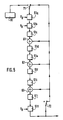
- the generator polynomial of degree 20 can be chosen primitive and irreducible so that the sequence is of maximum length (220-1): we will retain for example the polynomial 1 + x3 + x5 + x9 + x20 which corresponds to the pseudo-random sequence generator represented in FIG.
- the 20 cells controlled by the clock frequency F H being referenced 51a to 51t and supplemented by modulo adders 2, 61 to 63, switches 71 and 72 , and a circuit 81 for transferring the generator load word 50.
- the two switches 71 and 72 are in the left position when the generator is loaded from a 20-bit word stored in the circuit 81 and in the right position during the course of the pseudo-random sequence.
Landscapes
- Engineering & Computer Science (AREA)
- Multimedia (AREA)
- Signal Processing (AREA)
- Television Systems (AREA)
Applications Claiming Priority (2)
| Application Number | Priority Date | Filing Date | Title |
|---|---|---|---|
| FR8901020 | 1989-01-27 | ||
| FR8901020A FR2642597A1 (fr) | 1989-01-27 | 1989-01-27 | Etage d'emission pour systeme de transmission d'images de television a definition etendue, systeme de transmission incluant un tel etage, et etage de reception pour un tel systeme |
Publications (2)
| Publication Number | Publication Date |
|---|---|
| EP0380181A1 true EP0380181A1 (de) | 1990-08-01 |
| EP0380181B1 EP0380181B1 (de) | 1994-08-03 |
Family
ID=9378172
Family Applications (1)
| Application Number | Title | Priority Date | Filing Date |
|---|---|---|---|
| EP90200165A Expired - Lifetime EP0380181B1 (de) | 1989-01-27 | 1990-01-23 | Aussendungsstufe für ein in Auflösung erweitertes Fernsehbildübertragungssystem, Übertragungssystem, das eine solche Stufe umfasst und Empfangsstufe für ein solches System |
Country Status (5)
| Country | Link |
|---|---|
| US (1) | US5046091A (de) |
| EP (1) | EP0380181B1 (de) |
| JP (1) | JPH02238789A (de) |
| DE (1) | DE69011143T2 (de) |
| FR (1) | FR2642597A1 (de) |
Cited By (1)
| Publication number | Priority date | Publication date | Assignee | Title |
|---|---|---|---|---|
| EP0620690A1 (de) * | 1993-04-15 | 1994-10-19 | Matsushita Electric Industrial Co., Ltd. | Anordnung zur Verschlüsselung eines Videosignals |
Families Citing this family (2)
| Publication number | Priority date | Publication date | Assignee | Title |
|---|---|---|---|---|
| US5239582A (en) * | 1991-11-08 | 1993-08-24 | Macrovision Corporation | Ramp generation for preventing transitions with infinite short rise time in a video scrambling system |
| FR3004611B1 (fr) * | 2013-04-16 | 2015-05-15 | Morpho | Procede de gestion des ressources memoire d'un dispositif de securite, tel qu'une carte a puce, et dispositif de securite mettant en œuvre ledit procede. |
Citations (2)
| Publication number | Priority date | Publication date | Assignee | Title |
|---|---|---|---|---|
| EP0103339A1 (de) * | 1982-09-14 | 1984-03-21 | La Radiotechnique Portenseigne | Verfahren zum Verschlüsseln von Fernsehbildern und Vorrichtung zum Entschlüsseln derselben |
| EP0279625A2 (de) * | 1987-02-16 | 1988-08-24 | British Broadcasting Corporation | Übertragungssystem von Signalen |
Family Cites Families (1)
| Publication number | Priority date | Publication date | Assignee | Title |
|---|---|---|---|---|
| US4908697A (en) * | 1987-07-24 | 1990-03-13 | North American Philips Corporation | Two-line mac high definition television system |
-
1989
- 1989-01-27 FR FR8901020A patent/FR2642597A1/fr not_active Withdrawn
-
1990
- 1990-01-23 DE DE69011143T patent/DE69011143T2/de not_active Expired - Fee Related
- 1990-01-23 EP EP90200165A patent/EP0380181B1/de not_active Expired - Lifetime
- 1990-01-26 US US07/471,172 patent/US5046091A/en not_active Expired - Fee Related
- 1990-01-29 JP JP2016287A patent/JPH02238789A/ja active Pending
Patent Citations (2)
| Publication number | Priority date | Publication date | Assignee | Title |
|---|---|---|---|---|
| EP0103339A1 (de) * | 1982-09-14 | 1984-03-21 | La Radiotechnique Portenseigne | Verfahren zum Verschlüsseln von Fernsehbildern und Vorrichtung zum Entschlüsseln derselben |
| EP0279625A2 (de) * | 1987-02-16 | 1988-08-24 | British Broadcasting Corporation | Übertragungssystem von Signalen |
Non-Patent Citations (2)
| Title |
|---|
| IEEE TRANSACTIONS ON BROADCASTING, vol. BC-33, no. 4 décembre 1987, pages 116-123, IEEE, New York, US; M.A. ISNARDI et al.: "Encoding for compatibility and recoverability in the ACTV system" * |
| TECH. 3258-F, octobre 1986, pages 67-79, Union Européenne de Radiodiffusion, Bruxelles, BE; G.T. WATERS: "Spécification des systèmes de la famille MAC/paquets", partie 2, section 6: "Embrouillage de l'image" * |
Cited By (2)
| Publication number | Priority date | Publication date | Assignee | Title |
|---|---|---|---|---|
| EP0620690A1 (de) * | 1993-04-15 | 1994-10-19 | Matsushita Electric Industrial Co., Ltd. | Anordnung zur Verschlüsselung eines Videosignals |
| US5488658A (en) * | 1993-04-15 | 1996-01-30 | Matsushita Electric Industrial Co., Ltd. | Video signal scrambling and descrambling apparatus |
Also Published As
| Publication number | Publication date |
|---|---|
| DE69011143D1 (de) | 1994-09-08 |
| FR2642597A1 (fr) | 1990-08-03 |
| EP0380181B1 (de) | 1994-08-03 |
| JPH02238789A (ja) | 1990-09-21 |
| DE69011143T2 (de) | 1995-03-02 |
| US5046091A (en) | 1991-09-03 |
Similar Documents
| Publication | Publication Date | Title |
|---|---|---|
| EP0754391B1 (de) | Verfahren zur programmverteilung mit progressivem bedingtem zugriff und informationsstromtrennung sowie entsprechender empfänger | |
| BE1007882A3 (fr) | Procede de diffusion de programmes a acces conditionnel permettant un acces progressif et procede d'acces progressif a de tels programmes. | |
| EP0583202B1 (de) | Verfahren zur Aussendung und Empfang von Programmen mit bedingtem Zugang mit verringerter Programmschaltzeit | |
| EP0103339A1 (de) | Verfahren zum Verschlüsseln von Fernsehbildern und Vorrichtung zum Entschlüsseln derselben | |
| FR2565754A1 (fr) | Systeme de transmission de television | |
| FR2543387A1 (de) | ||
| EP0119945A1 (de) | Verfahren und Anlage zur Verschleierung und Entschleierung von Fernsehbildern | |
| EP0380181B1 (de) | Aussendungsstufe für ein in Auflösung erweitertes Fernsehbildübertragungssystem, Übertragungssystem, das eine solche Stufe umfasst und Empfangsstufe für ein solches System | |
| EP0196681B1 (de) | Verfahren und Vorrichtungen zum Entschlüsseln oder Verschlüsseln angewendet auf der MAC-Fernsehnorm | |
| EP0126495B1 (de) | Entzerrer für durch zyklische Verwechslung verschlüsselte Fernsehbilder | |
| EP0188030A2 (de) | Verfahren zur Kodierung und Dekodierung von Audioinformationen und Vorrichtung zur Durchführung des Verfahrens | |
| EP0158383A1 (de) | Vorrichtung zum Entschlüsseln und Dekodieren von Fernsehbildern kodiert gemäss Norm MAC und verschleiert durch auf die Videosignale angewendete Kreispermutationen | |
| EP0365090A1 (de) | Einrichtung zum Verdoppeln der Rate von Fernsehbild-Signalen, und Fernsehbild-Dekodierer mit einer solchen Einrichtung | |
| EP0338915B1 (de) | Verfahren zur Übertragung von Fernsehprogrammen nach der Mac-Paket-Norm sowie Anordnung zur Durchführung des Verfahrens | |
| EP0194186B1 (de) | Verfahren zur Übertragung von Daten durch Einfügen in ein analoges Sprachsignal und Vorrichtungen zur Durchführung dieses Verfahrens | |
| FR2549332A1 (fr) | Procede et dispositif pour empecher l'enregistrement non autorise d'un signal video de television | |
| EP0395507B1 (de) | Sende- und Empfangssystem zum Übertragen von beweglichen Farbbildern und Ton über unabhängige Kanäle | |
| FR2700911A1 (fr) | Procédé et dispositif de codage-décodage de canal d'un signal de télévision numérique haute définition diffusé par satellite. | |
| FR2656189A1 (fr) | Systeme et decodeur de signal haute definition de la famille mac/paquet, compatibles avec une transmission en large bande et en bande etroite. | |
| EP0338594B1 (de) | Fernsehsignalentschlüsselungsgerät | |
| FR2690805A1 (fr) | Dispositif d'insertion de programmes de télévision numérique sur un canal de transmission ou de diffusion et dispositif de réception de tels programmes. | |
| WO2003107655A1 (fr) | Procede et interface de communication entre un serveur et au moins un terminal-recepteur | |
| FR2590432A1 (fr) | Procede et dispositif de decodage et de dechiffrement de signaux ayant subi un codage de type mac et un chiffrement par permutation circulaire autour d'un ou de deux points de coupure, et dispositif de codage et de chiffrement fonctionnant de facon similaire | |
| FR2641659A1 (fr) | Procede de transmission de signaux supplementaires analogiques dans un signal video-composite de television et dispositif de mise en oeuvre de ce procede | |
| FR2564677A1 (fr) | Systeme de diffusion de signaux de television a multiplexage temporel de composantes analogiques et dispositif pour le passage de ce systeme a un systeme de debit deux fois plus faible |
Legal Events
| Date | Code | Title | Description |
|---|---|---|---|
| PUAI | Public reference made under article 153(3) epc to a published international application that has entered the european phase |
Free format text: ORIGINAL CODE: 0009012 |
|
| AK | Designated contracting states |
Kind code of ref document: A1 Designated state(s): DE FR GB |
|
| 17P | Request for examination filed |
Effective date: 19910130 |
|
| 17Q | First examination report despatched |
Effective date: 19930128 |
|
| GRAA | (expected) grant |
Free format text: ORIGINAL CODE: 0009210 |
|
| AK | Designated contracting states |
Kind code of ref document: B1 Designated state(s): DE FR GB |
|
| REF | Corresponds to: |
Ref document number: 69011143 Country of ref document: DE Date of ref document: 19940908 |
|
| GBT | Gb: translation of ep patent filed (gb section 77(6)(a)/1977) |
Effective date: 19941026 |
|
| PG25 | Lapsed in a contracting state [announced via postgrant information from national office to epo] |
Ref country code: GB Effective date: 19950123 |
|
| PLBE | No opposition filed within time limit |
Free format text: ORIGINAL CODE: 0009261 |
|
| STAA | Information on the status of an ep patent application or granted ep patent |
Free format text: STATUS: NO OPPOSITION FILED WITHIN TIME LIMIT |
|
| 26N | No opposition filed | ||
| GBPC | Gb: european patent ceased through non-payment of renewal fee |
Effective date: 19950123 |
|
| PG25 | Lapsed in a contracting state [announced via postgrant information from national office to epo] |
Ref country code: FR Effective date: 19950929 |
|
| PG25 | Lapsed in a contracting state [announced via postgrant information from national office to epo] |
Ref country code: DE Effective date: 19951003 |
|
| REG | Reference to a national code |
Ref country code: FR Ref legal event code: ST |