EP0379552B1 - Procede de diffusion d'air et appareil utilise dans ledit procede - Google Patents
Procede de diffusion d'air et appareil utilise dans ledit procede Download PDFInfo
- Publication number
- EP0379552B1 EP0379552B1 EP89907763A EP89907763A EP0379552B1 EP 0379552 B1 EP0379552 B1 EP 0379552B1 EP 89907763 A EP89907763 A EP 89907763A EP 89907763 A EP89907763 A EP 89907763A EP 0379552 B1 EP0379552 B1 EP 0379552B1
- Authority
- EP
- European Patent Office
- Prior art keywords
- air
- flow
- guide member
- air flow
- wall surface
- Prior art date
- Legal status (The legal status is an assumption and is not a legal conclusion. Google has not performed a legal analysis and makes no representation as to the accuracy of the status listed.)
- Expired - Lifetime
Links
- 238000000034 method Methods 0.000 title claims abstract description 23
- 230000005484 gravity Effects 0.000 claims abstract description 9
- 238000002347 injection Methods 0.000 description 11
- 239000007924 injection Substances 0.000 description 11
- 230000001105 regulatory effect Effects 0.000 description 6
- 238000009423 ventilation Methods 0.000 description 6
- 230000000694 effects Effects 0.000 description 5
- 230000003247 decreasing effect Effects 0.000 description 2
- 238000007664 blowing Methods 0.000 description 1
- 238000010276 construction Methods 0.000 description 1
- 230000001276 controlling effect Effects 0.000 description 1
- 238000010438 heat treatment Methods 0.000 description 1
- 230000001939 inductive effect Effects 0.000 description 1
- 238000009434 installation Methods 0.000 description 1
- 239000002184 metal Substances 0.000 description 1
- 239000000243 solution Substances 0.000 description 1
Images


Classifications
-
- F—MECHANICAL ENGINEERING; LIGHTING; HEATING; WEAPONS; BLASTING
- F24—HEATING; RANGES; VENTILATING
- F24F—AIR-CONDITIONING; AIR-HUMIDIFICATION; VENTILATION; USE OF AIR CURRENTS FOR SCREENING
- F24F7/00—Ventilation
- F24F7/04—Ventilation with ducting systems, e.g. by double walls; with natural circulation
- F24F7/06—Ventilation with ducting systems, e.g. by double walls; with natural circulation with forced air circulation, e.g. by fan positioning of a ventilator in or against a conduit
- F24F7/08—Ventilation with ducting systems, e.g. by double walls; with natural circulation with forced air circulation, e.g. by fan positioning of a ventilator in or against a conduit with separate ducts for supplied and exhausted air with provisions for reversal of the input and output systems
-
- F—MECHANICAL ENGINEERING; LIGHTING; HEATING; WEAPONS; BLASTING
- F24—HEATING; RANGES; VENTILATING
- F24F—AIR-CONDITIONING; AIR-HUMIDIFICATION; VENTILATION; USE OF AIR CURRENTS FOR SCREENING
- F24F13/00—Details common to, or for air-conditioning, air-humidification, ventilation or use of air currents for screening
- F24F13/02—Ducting arrangements
- F24F13/06—Outlets for directing or distributing air into rooms or spaces, e.g. ceiling air diffuser
- F24F13/068—Outlets for directing or distributing air into rooms or spaces, e.g. ceiling air diffuser formed as perforated walls, ceilings or floors
Definitions
- the present invention concerns an air distribution procedure and an apparatus used in the procedure.
- the temperature of the incoming air is maintained approximately constant and the air quantity is increased or decreased in accordance with changes in loading.
- problems arise because of the thermal forces.
- the incoming air means usually operates well but when the air quantity is decreased the injection is not able to arise upwards because of the small starting speed, and it falls down and causes draught.
- the injection range remains in general short, whereby air circulation and comfort are poor.
- the injection range and the starting speed are clearly interrelated. For the injection range to remain approximately constant, the starting speed is required to stay within a given range. However, with a small air quantity, the starting speed should grow in order to overcome the thermal counterforces.
- the object of the invention is a procedure and an apparatus in which the above-mentioned drawbacks have been overcome.
- the present invention provides an air distribution procedure in which an airflow is carried into the air space of a room from an air inlet comprising louvre means and a guide member controlled and closable by gravity, the air flow being directed upwards and conforming to a wall surface, characterized in that the air flow is so directed to conform to the wall surface that with small quantities of air the throw length of the air flow is substantially at least as long as with great quantities of air.
- the invention also provides an air inlet for delivering an airflow into the air space of a room so that the air flows upwards and conforming to a wall surface, the air inlet comprising louvre means and a guide member closable by gravity which controls the size of an air flow passage for controlling the velocity of the air flow, characterized in that the air inlet so directs the air flow to conform to the wall surface that with small quantities of air the throw length of the air flow is substantially at least as long as with great quantities of air.
- the incoming air is brought into the room space through an incoming air means by focussing the air injection onto the guide plate which is for closing the flow duct and which is controlled by gravity.
- the force on the guide plate due to the air jet is counteracted by the torque in the opposite direction caused by the weight of the guide plate which is supported at a bearing point.
- a given speed can be measured on the surface of the louvre, being approximately constant over the entire surface.
- the guide plate directs a small volumetric flow at high speed into a distributing chamber from where it passes through a louvre into the room space.
- a volumetric flow rate is small, a high flow speed is achieved and a sufficient flow length for the flow results.
- the high speed is focussed to conform to the wall surface. Accordingly, the Coanda effect is utilised in the invention and the airflow from the incoming air means adjacent the wall surface is directed upwards.
- a high-speed air flow may be focussed advantageously via a wall surface and/or batteries and/or window surfaces.
- the Coanda effect of the vertical surface is made use of.
- the surface temperature of the window and/or wall can be changed by means of incoming air. Consequently, the cool draught can be obstructed from the structures and efficiently reduce the heat loading caused by the sun.
- the heat emittance from said batteries is moreover aided.
- air may be carried from outside the staying zone and the air nucleus injection is circulated past the staying zone. Therefore, no draught is caused from the air injection to the staying zone of the room space.
- a longer than normal throw length may be available for the air injection without causing any harm to a person staying in said room.
- a united control system of ventilation and heating may also be implemented.
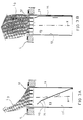
- Fig. 1A the ventilation procedure of the invention is presented schematically and in a first extreme position of the actuating means.
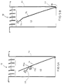
- Fig. 1B the procedure of the invention is presented when the adjustment means is moved to a second extreme position.
- Figs 2A and 2B is presented schematically the operation of the incoming air means.
- Fig. 2A corresponds to the position of the incoming air means of Fig. 1A, respectively
- Fig. 2B corresponds to the position of the actuating means of Fig. 1B.
- Fig. 3A is presented a section I-I of Fig. 2A, respectively, in Fig. 3B is presented a section II-II of Fig. 2B.
- Fig. 4A is presented the embodiment of the invention in which the deviation of a high-speed air current is not implemented with the aid of a louvre, but the air current is directed directly out through the louvre in the direction of the wall surfaces of the distribution chamber.
- Fig. 4B is presented the embodiment of the incoming air means used in the procedure of the invention in which the flow from the distribution chamber is deviated with the aid of the guide surfaces of the slats of the louvre.
- Fig. 5A is presented the embodiment of the incoming air means of the invention in which the member regulating the air flow comprises a separately disposed and disposable component guiding the flow.
- Fig. 5B is presented an embodiment of the incoming air means of the invention in which on the guide plate is disposed an air flow guide part disposable according to the temperature.
- Fig. 6 is presented the disposition of the incoming air means in the window sill underneath the window.
- Fig. 1A is presented a cross-section of a room space H.
- the wall surface is indicated by letter S and the floor by L.
- the incoming air flow is carried from an incoming air means 10, the louvre section thereof being disposed in the adjacency of the floor, advantageously on the floor level.
- the incoming air flow is carried upwards from below and conforming to the wall surface S.
- the flow is entered advantageously so that it sweeps the inner surfaces of the window I.
- the flow ascends conforming to the wall S to the adjacency of the ceiling K of the room space and there travels conforming to the ceiling.
- the flow rate is required to be sufficient in order to provide circulation for the staying zone of the room space H.
- the quantity of flowing entering the incoming air means 10 through the duct T can be regulated in the room G with an adjustment means 20.
- an adjustment unit 21 a control message is carried to an adjustment means 22 located in a duct E, said means regulating the volumetric flow of the air flow.
- Fig. 1B is indicated an adjustment position of the incoming air means 10 in which through the incoming air means a higher quantity of air is carried into the room space H than in the instance of Fig. 1A.
- the adjustment is performed in the room H with the adjustment means 20.
- the air is moved into the room space H upwards from below and so that the incoming air is disposed to enter the room space H advantageously from an incoming means in the adjacency of the floor.
- An essential feature of the invention is moreover that the incoming air means has been disposed to be located in the adjacency of one wall surface of the room H. One or several incoming air means may be placed in the adjacency of said wall surface.
- Figs 2A and 2B the adjustments corresponding to Figs 1A and 1B are presented.
- a high-speed air flow L2 is directed, conforming to a wall surface and/or window surface, straight upwards in the room space.
- a respective position of the incoming air means In the lower part of Fig. 2A is presented a respective position of the incoming air means. The air mass is small but the flow rate is nevertheless great.
- the air flow L2 is made to extend over a sufficient distance using the incoming air means 10 of the invention, the air flow guide plate 14 whereof compressing the air flow and reducing the flow cross-sectional surface in the flow duct 13.
- the guide plate 14 is not intended to shut the entire duct 13 but only a section thereof, whereby the flow is regulated in order to obtain speed.
- Fig. 2B is presented a completely open position of the air flow guide plate 14 of the incoming air means.
- the quantity of the air flow is great, and the throw length of the air flow is, nevertheless, equivalent to the instance of small air mass of Fig. 2A.
- Fig. 3A is presented the operational position of Fig. 2A and in Fig. 3B is presented the operational position of the incoming air means of Fig. 2B.
- the discharge of the air flow from the incoming air means 10 is indicated by arrows L2 and L3.
- the air flow is directed to pass, conforming to the wall surface and/or the window surface and/or the battery surface, into the room space H.
- the nuclear injection of the flow does not hit the staying zone of the room space H.
- the air mass is great and the throw length equivalent to the instance shown in Fig. 3A.
- Fig. 4A is presented an embodiment of the ventilation procedure and the incoming air means 10 of the invention in which a high-speed air flow is guided, conforming to the wall 13' of an air duct 13, directly to the adjacency of the wall surface S.
- the central axis X of the duct 13 is, when the means 10 is disposed to be in use, in the direction of the plane of the wall surface S.
- the incoming air means 10 comprises a body envelope 11 of the incoming air means 10. On an end of the body envelope 11 is disposed a louvre 12, comprising a plurality of adjacent slats 12a regulating the flow.
- the body envelope 11 encloses and delimits therein a flow duct 13.
- a guide plate 14 In the flow duct 13 is disposed a guide plate 14 guiding the air flow, and regulating the air flow, its flow rate and/or quantity of flowing.
- the guide plate 14 is pivotally carried to turn at one end 14a.
- the guide plate 14 is disposed in the flow duct 13 and it is disposed, when the air flow is not exerting an effect on the guide plate, to be in a position in which it totally shuts the flow duct 13.
- a balance position of the guide plate may also be formed between said extreme positions.
- the end to the louvre 12 of the guide plate 14 comprises a section 15 deviating the flow which on the surface plane is a plate-like section obliquely relative to the plane of the guide plate 14.
- a counterweight 16 which can be disposed on the plate 14. Changing the location of the counterweight, the torque caused by the counterweight is changed relative to the pivoting point 17, and to the force required of the air flow to move the guide plate 14.
- an adjustment means of the counterweight 16 advantageously an adjustment screw.
- the counterweight may be attached to different positions in different recesses located in the guide plate 14, or it can be moved to a different position when the screw 16' moves in the groove of the guide plate 14.
- the guide plate 14 has been pivoted to turn carried by a collar component 18. The guide plate 14 compresses the flow and at the same time, the flow rate increases.
- the guide plate 14 compresses the flow significantly and the flow rate increases. Said high-speed flow is guided from the incoming chamber 19 directly past the slats 12a conforming to the wall surface S.
- a high-speed flow of small quantity of air also on the wall surface In the instance of Fig. 4B a high-speed flow of small quantity of air also on the wall surface.
- the turning point of the guide plate 14 is located on the opposite wall compared with the instance of Fig. 4A.
- the flow is directed from the distribution chamber 19 through the surfaces 12a', said surfaces deviating the flow, of the slats 12a of the louvre 12 onto the wall surface S.
- Conforming to the wall surface the air flow passes upwards in the room space and sweeps the window surfaces and/or battery surfaces, and in the latter instance, increases the transfer of heat into the air of the room space H.
- a high-speed air flow induces the air of the room space H to circulate as shown in Figs 1A and 1B.
- Fig. 5A is presented an embodiment of the invention in which the guide plate 14 comprises a guide section 15 guiding the flow in oblique position relative to the plane of the guide plate.
- the guiding section 15 guiding the flow has been attached to be separate on the guide plate 14.
- the section 15 may moreover be positioned in various locations of the plate in order to achieve the desired adjustment incident.
- the base part 15b of the plate 15 comprises an adjustment screw 15c with the aid of which the component 15 guiding the flow can be disposed advantageously relative to the guide plate 14 in the groove of the guide plate 14 or in separate recesses provided for the adjustment screw.
- Fig. 5B is presented an embodiment of the invention in which the guide plate 14 comprises a guiding component 15 located in the opposite end relative to the turning point 14a of the guide plate 14, said component being a bent part of the plate 14 or a separate part attached to the plate 14.
- the guiding component 15 has been disposed on the end of the air flow guide plate 14 and said part is a bi-metallic part which according to the temperature bends into a position determined by the temperature. It is thus possible with said bi-metal component to adjust the air flow also in dependence on the temperature.
- Fig. 6 is presented the embodiment of the invention in which the incoming air means 10 has been disposed in the window sill under the window I.
- the incoming air flow has thus been disposed to sweep directly the window surfaces.
- the inducing flow emitted from the incoming air means also carries the leakage flow emitted through the window therealong and in such manner, the flow entering from the incoming air means serves as a kind of curtain injection.
- the efficiency of the ventilation remains good because the throw length is approximately constant at various volumetric flows. Efficient mixing of the air already in the lower part improves the quality of the air in the staying zone.
- the space available for the throw length is significantly larger than in conventional in-blow designs.
- the air distribution means is inconspicuous in outlook and goes well with furniture and constructions.
- the interior flows and temperature are easy to control
- the effect of the temperature of the incoming air on the throw length may also be easily be compensated e.g. using the bi-metallic guide shown in Fig. 5B. Therefore, the starting speed and consequently, also the throw length are easy to adjust and, for instance, be limited to a given maximum value.
Landscapes
- Engineering & Computer Science (AREA)
- Chemical & Material Sciences (AREA)
- Combustion & Propulsion (AREA)
- Mechanical Engineering (AREA)
- General Engineering & Computer Science (AREA)
- Air-Flow Control Members (AREA)
- Duct Arrangements (AREA)
Abstract
Claims (13)
- Procédé de diffusion d'air dans lequel un flux d'air est déversé dans le volume d'air d'une pièce à partir d'une prise (10) d'air comprenant des moyens formant claire-voie (12) et un élément de guidage (14) commandé et pouvant se fermer par gravité, le flux d'air étant dirigé vers le haut et suivant une surface de mur (S), caractérisé en ce que le flux d'air est dirigé pour suivre la surface du mur (S) de telle façon qu'avec de petites quantités d'air la distance d'injection du flux d'air soit sensiblement au moins aussi grande qu'avec de grandes quantités d'air.
- Procédé selon la Revendication 1, dans lequel le flux d'air est dirigé pour suivre la surface du mur avec une vitesse plus grande pour de petites quantités d'air que pour de grandes quantités d'air.
- Procédé selon la Revendication 1 ou 2, dans lequel le flux d'air est ensuite dirigé le long d'un plafond (K) de la pièce (H), le plafond (K) étant adjacent à ladite surface du mur (S), l'air circulant vers un conduit (C) de sortie, grâce à quoi une circulation d'air dans la pièce (H) est créée par le flux d'air.
- Procédé selon l'une quelconque des revendications précédentes, dans lequel le flux d'air est guidé vers le plafond (K) de la pièce (H) en suivant les surfaces de batteries et/ou d'une fenêtre.
- Prise (10) d'air pour délivrer un flux d'air dans le volume d'air d'une pièce de façon que l'air s'élève et suive la surface d'un mur (S), la prise d'air comprenant des moyens formant claire-voie(12) et un élément de guidage (14) pouvant se fermer par gravité, qui commande les dimensions d'un passage d'écoulement d'air pour commander la vitesse du flux d'air, caractérisée en ce que la prise (10) d'air dirige le flux d'air pour qu'il suive la surface d'un mur (S) de telle façon qu'avec de petites quantités d'air la distance d'injection du flux d'air soit sensiblement au moins aussi grande qu'avec de grandes quantités d'air.
- Prise d'air selon la Revendication 5, dans laquelle l'élément de guidage (14) est monté rotatif dans un conduit d'écoulement (13) et ferme partiellement le conduit d'écoulement (13) dans une première position, et suit sensiblement une paroi (11') du conduit d'écoulement (13) dans une seconde position.
- Prise d'air selon la Revendication 5 ou 6, dans laquelle les moyens formant claire-voie(12) sont en aval de l'élément de guidage (14).
- Prise d'air selon l'une quelconque des revendications 5 à 7, dans laquelle l'élément de guidage (14) comporte une plaque sensiblement plane.
- Prise d'air selon l'une quelconque des revendications 5 à 8, dans laquelle l'élément de guidage (14) est supporté d'une manière rotative sur un bord.
- Prise d'air selon la Revendication 9, dans laquelle l'élément de guidage (14) comporte en outre un composant de guidage (15) disposé d'une manière oblique par rapport à la surface plane de l'élément de guidage (14).
- Prise d'air selon la Revendication 10, dans laquelle le composant de guidage (15) comporte une partie bimétallique dont la position par rapport à l'élément de guidage (14) varie en fonction de la température.
- Prise d'air selon l'une quelconque des revendications 5 à 11, dans laquelle la plaque de guidage (14) comporte en outre une masse supplémentaire (16) dont la position sur la plaque de guidage (14) est modifiable.
- Prise d'air selon la Revendication 8, dans laquelle l'élément de guidage (14) comporte une masse supplémentaire (16).
Priority Applications (1)
| Application Number | Priority Date | Filing Date | Title |
|---|---|---|---|
| AT89907763T ATE89391T1 (de) | 1988-06-30 | 1989-06-22 | Luftverteilungsverfahren und vorrichtung dazu. |
Applications Claiming Priority (2)
| Application Number | Priority Date | Filing Date | Title |
|---|---|---|---|
| FI883127 | 1988-06-30 | ||
| FI883127A FI80518C (fi) | 1988-06-30 | 1988-06-30 | Luftfoerdelningsfoerfarande och anlaeggning foer anvaendning vid foerfarandet. |
Publications (2)
| Publication Number | Publication Date |
|---|---|
| EP0379552A1 EP0379552A1 (fr) | 1990-08-01 |
| EP0379552B1 true EP0379552B1 (fr) | 1993-05-12 |
Family
ID=8526745
Family Applications (1)
| Application Number | Title | Priority Date | Filing Date |
|---|---|---|---|
| EP89907763A Expired - Lifetime EP0379552B1 (fr) | 1988-06-30 | 1989-06-22 | Procede de diffusion d'air et appareil utilise dans ledit procede |
Country Status (3)
| Country | Link |
|---|---|
| EP (1) | EP0379552B1 (fr) |
| FI (1) | FI80518C (fr) |
| WO (1) | WO1990000241A1 (fr) |
Families Citing this family (2)
| Publication number | Priority date | Publication date | Assignee | Title |
|---|---|---|---|---|
| US6019677A (en) * | 1997-08-22 | 2000-02-01 | York International Corporation | Modular integrated terminals and associated systems for heating and cooling |
| KR101550193B1 (ko) | 2013-09-23 | 2015-09-04 | 한국생산기술연구원 | 와류식 배출 후드 |
Family Cites Families (2)
| Publication number | Priority date | Publication date | Assignee | Title |
|---|---|---|---|---|
| JPS5049847A (fr) * | 1973-09-05 | 1975-05-02 | ||
| SE445486B (sv) * | 1984-09-05 | 1986-06-23 | Flaekt Ab | Anordning for tryckreglering i ett ventilationssystem |
-
1988
- 1988-06-30 FI FI883127A patent/FI80518C/fi not_active IP Right Cessation
-
1989
- 1989-06-22 WO PCT/FI1989/000121 patent/WO1990000241A1/fr not_active Ceased
- 1989-06-22 EP EP89907763A patent/EP0379552B1/fr not_active Expired - Lifetime
Also Published As
| Publication number | Publication date |
|---|---|
| FI883127A0 (fi) | 1988-06-30 |
| FI80518C (fi) | 1990-06-11 |
| FI883127L (fi) | 1989-12-31 |
| WO1990000241A1 (fr) | 1990-01-11 |
| FI80518B (fi) | 1990-02-28 |
| EP0379552A1 (fr) | 1990-08-01 |
Similar Documents
| Publication | Publication Date | Title |
|---|---|---|
| CA2223751C (fr) | Procede et moyen permettant une ventilation au plafond amelioree | |
| US4448111A (en) | Variable venturi, variable volume, air induction input for an air conditioning system | |
| US4890544A (en) | Air distribution system | |
| US5197920A (en) | Element for user in a heating and air conditioning ductwork system | |
| EP1460350A1 (fr) | Appareil de conditionnement d'air | |
| JPH0316583B2 (fr) | ||
| CA2224255C (fr) | Procede et dispositif d'aeration amelioree par paroi laterale | |
| EP0379552B1 (fr) | Procede de diffusion d'air et appareil utilise dans ledit procede | |
| PL204618B1 (pl) | Urządzenie i sposób ogrzewania i/lub chłodzenia pomieszczenia | |
| FI831682L (fi) | Rost foer foerbraenning av fasta braenslen i spisar, haerdar, ugnar och liknande | |
| JP2002130730A (ja) | 下吹出し上吸込み式空調機の改良 | |
| US5520580A (en) | Air handler to control air supply in confinement buildings for poultry and livestock | |
| WO1994000719A1 (fr) | Diffuseur d'air de plafond a ailette mobile | |
| JPH0311655Y2 (fr) | ||
| JPH055390Y2 (fr) | ||
| US2921514A (en) | Convectors | |
| JPS6115335B2 (fr) | ||
| JP7141656B2 (ja) | 吹出口装置 | |
| DE68906527T2 (de) | Luftverteilungsverfahren und vorrichtung dazu. | |
| KR101054792B1 (ko) | 과압배출용 댐퍼 | |
| JPS62757A (ja) | 風向制御型送風装置 | |
| JP2021011973A (ja) | エアカーテンシステム | |
| SE441958B (sv) | Tilluftsdon med variabelt tilluftsflode for ventilations- och luftkonditioneringsanleggningar | |
| JPH0434354Y2 (fr) | ||
| KR100315801B1 (ko) | 공기조화기의 실내기 |
Legal Events
| Date | Code | Title | Description |
|---|---|---|---|
| PUAI | Public reference made under article 153(3) epc to a published international application that has entered the european phase |
Free format text: ORIGINAL CODE: 0009012 |
|
| 17P | Request for examination filed |
Effective date: 19900212 |
|
| AK | Designated contracting states |
Kind code of ref document: A1 Designated state(s): AT BE CH DE FR GB IT LI LU NL SE |
|
| 17Q | First examination report despatched |
Effective date: 19901206 |
|
| GRAA | (expected) grant |
Free format text: ORIGINAL CODE: 0009210 |
|
| AK | Designated contracting states |
Kind code of ref document: B1 Designated state(s): AT BE CH DE FR GB IT LI LU NL SE |
|
| PG25 | Lapsed in a contracting state [announced via postgrant information from national office to epo] |
Ref country code: IT Free format text: LAPSE BECAUSE OF FAILURE TO SUBMIT A TRANSLATION OF THE DESCRIPTION OR TO PAY THE FEE WITHIN THE PRESCRIBED TIME-LIMIT;WARNING: LAPSES OF ITALIAN PATENTS WITH EFFECTIVE DATE BEFORE 2007 MAY HAVE OCCURRED AT ANY TIME BEFORE 2007. THE CORRECT EFFECTIVE DATE MAY BE DIFFERENT FROM THE ONE RECORDED. Effective date: 19930512 Ref country code: CH Effective date: 19930512 Ref country code: AT Effective date: 19930512 Ref country code: BE Effective date: 19930512 Ref country code: LI Effective date: 19930512 Ref country code: NL Effective date: 19930512 |
|
| REF | Corresponds to: |
Ref document number: 89391 Country of ref document: AT Date of ref document: 19930515 Kind code of ref document: T |
|
| REF | Corresponds to: |
Ref document number: 68906527 Country of ref document: DE Date of ref document: 19930617 |
|
| PG25 | Lapsed in a contracting state [announced via postgrant information from national office to epo] |
Ref country code: LU Free format text: LAPSE BECAUSE OF NON-PAYMENT OF DUE FEES Effective date: 19930630 |
|
| ET | Fr: translation filed | ||
| REG | Reference to a national code |
Ref country code: CH Ref legal event code: PL |
|
| NLV1 | Nl: lapsed or annulled due to failure to fulfill the requirements of art. 29p and 29m of the patents act | ||
| EAL | Se: european patent in force in sweden |
Ref document number: 89907763.0 |
|
| PGFP | Annual fee paid to national office [announced via postgrant information from national office to epo] |
Ref country code: FR Payment date: 19960529 Year of fee payment: 8 |
|
| PGFP | Annual fee paid to national office [announced via postgrant information from national office to epo] |
Ref country code: GB Payment date: 19960613 Year of fee payment: 8 |
|
| PGFP | Annual fee paid to national office [announced via postgrant information from national office to epo] |
Ref country code: DE Payment date: 19960731 Year of fee payment: 8 |
|
| PG25 | Lapsed in a contracting state [announced via postgrant information from national office to epo] |
Ref country code: GB Free format text: LAPSE BECAUSE OF NON-PAYMENT OF DUE FEES Effective date: 19970622 |
|
| GBPC | Gb: european patent ceased through non-payment of renewal fee |
Effective date: 19970622 |
|
| PG25 | Lapsed in a contracting state [announced via postgrant information from national office to epo] |
Ref country code: FR Free format text: LAPSE BECAUSE OF NON-PAYMENT OF DUE FEES Effective date: 19980227 |
|
| PG25 | Lapsed in a contracting state [announced via postgrant information from national office to epo] |
Ref country code: DE Free format text: LAPSE BECAUSE OF NON-PAYMENT OF DUE FEES Effective date: 19980303 |
|
| REG | Reference to a national code |
Ref country code: FR Ref legal event code: ST |
|
| REG | Reference to a national code |
Ref country code: FR Ref legal event code: ST |
|
| PGFP | Annual fee paid to national office [announced via postgrant information from national office to epo] |
Ref country code: SE Payment date: 20020617 Year of fee payment: 14 |
|
| PG25 | Lapsed in a contracting state [announced via postgrant information from national office to epo] |
Ref country code: SE Free format text: LAPSE BECAUSE OF NON-PAYMENT OF DUE FEES Effective date: 20030623 |
|
| EUG | Se: european patent has lapsed | ||
| PLBE | No opposition filed within time limit |
Free format text: ORIGINAL CODE: 0009261 |
|
| STAA | Information on the status of an ep patent application or granted ep patent |
Free format text: STATUS: NO OPPOSITION FILED WITHIN TIME LIMIT |