EP0379206B1 - Conveyor having self-propelled carrier - Google Patents
Conveyor having self-propelled carrier Download PDFInfo
- Publication number
- EP0379206B1 EP0379206B1 EP90101035A EP90101035A EP0379206B1 EP 0379206 B1 EP0379206 B1 EP 0379206B1 EP 90101035 A EP90101035 A EP 90101035A EP 90101035 A EP90101035 A EP 90101035A EP 0379206 B1 EP0379206 B1 EP 0379206B1
- Authority
- EP
- European Patent Office
- Prior art keywords
- rail
- carrier
- low
- running
- drive wheel
- Prior art date
- Legal status (The legal status is an assumption and is not a legal conclusion. Google has not performed a legal analysis and makes no representation as to the accuracy of the status listed.)
- Expired - Lifetime
Links
Images




Classifications
-
- B—PERFORMING OPERATIONS; TRANSPORTING
- B66—HOISTING; LIFTING; HAULING
- B66C—CRANES; LOAD-ENGAGING ELEMENTS OR DEVICES FOR CRANES, CAPSTANS, WINCHES, OR TACKLES
- B66C9/00—Travelling gear incorporated in or fitted to trolleys or cranes
- B66C9/14—Trolley or crane travel drives
-
- B—PERFORMING OPERATIONS; TRANSPORTING
- B62—LAND VEHICLES FOR TRAVELLING OTHERWISE THAN ON RAILS
- B62D—MOTOR VEHICLES; TRAILERS
- B62D65/00—Designing, manufacturing, e.g. assembling, facilitating disassembly, or structurally modifying motor vehicles or trailers, not otherwise provided for
- B62D65/02—Joining sub-units or components to, or positioning sub-units or components with respect to, body shell or other sub-units or components
- B62D65/18—Transportation, conveyor or haulage systems specially adapted for motor vehicle or trailer assembly lines
-
- B—PERFORMING OPERATIONS; TRANSPORTING
- B61—RAILWAYS
- B61C—LOCOMOTIVES; MOTOR RAILCARS
- B61C13/00—Locomotives or motor railcars characterised by their application to special systems or purposes
- B61C13/04—Locomotives or motor railcars characterised by their application to special systems or purposes for elevated railways with rigid rails
-
- Y—GENERAL TAGGING OF NEW TECHNOLOGICAL DEVELOPMENTS; GENERAL TAGGING OF CROSS-SECTIONAL TECHNOLOGIES SPANNING OVER SEVERAL SECTIONS OF THE IPC; TECHNICAL SUBJECTS COVERED BY FORMER USPC CROSS-REFERENCE ART COLLECTIONS [XRACs] AND DIGESTS
- Y02—TECHNOLOGIES OR APPLICATIONS FOR MITIGATION OR ADAPTATION AGAINST CLIMATE CHANGE
- Y02T—CLIMATE CHANGE MITIGATION TECHNOLOGIES RELATED TO TRANSPORTATION
- Y02T30/00—Transportation of goods or passengers via railways, e.g. energy recovery or reducing air resistance
Definitions
- the present invention relates to a conveyor comprising a plurality of self-propelled carriers adapted to run along a rail, the rail having a first drive wheel bearing surface facing upward and a plurality of downward teeth formed at least at a gradient portion of the rail, each of the carriers having a first drive wheel rollable on the wheel bearing surface of the rail, a first electric motor for driving the first drive wheel and a gear meshable with the teeth of the rail.
- the power-and-free trolley conveyor employs chains and therefore has the problem of giving off a great noise and being unable to drive the carriers at a high speed in transport zones or the like other than the work zone.
- conveyors having a plurality of self-propelled carriers have been proposed to ensure a reduced noise and to drive the carriers at a higher speed.
- the self-propelled carrier of the conventional conveyor of the first-mentioned type has one drive wheel rollable on a rail and one electric motor for driving the wheel.
- the conveyor therefore has the problem that when the rail has a gradient, the drive wheel slips at the gradient portion, making the carrier unable to run smoothly.
- a conveyor is also proposed wherein a rack having upward teeth is provided at a rail gradient portion, and a pinion mounted on the same shaft as the drive wheel of a carrier is adapted to roll on the rack at the gradient portion (see Examined Japanese Patent Publication SHO 52-97575).
- this arrangement has a problem in respect of strenght since a load acts on the pinion at the shaft end of the drive wheel. Further, because the pinion as positioned on the rack is subjected to the load of the carrier, the pinion fails to mesh with the rack smoothly, while these members undergo marked abrasion.
- FR-A-1.490 ⁇ .620 ⁇ shows a conveyor comprising self-propelled carriers running along a rail.
- the carriers are provided with a drive wheel rolling on the rail and with a gear meshing wich downward teeth on the lower surface of the rail, both the drive wheel and the gear being driven by one single motor.
- the single motor conventionally used for driving the drive wheel encounters the problem of an insufficient torque when driving the carrier at the low speed.
- An object of the present invention is to provide a conveyor comprising self-propelled carriers which are adapted to run along rail gradient portions without slipping.
- Another object of the invention is to provide a conveyor comprising self-propelled carriers each having a gear which is meshable with toothed portions smoothly with diminished wear.
- Still another object of the invention is to provide a conveyor comprising self-propelled carriers which is free of the likelihood that the drive torque will become insufficient during running at a low speed.
- the present invention provides a second electric motor for driving the gear and the rail is formed at a required portion with a friction roller bearing surface facing downward and each of the carriers has a friction roller positionable in pressing contact with the roller bearing surface from below and rotatable by the second electric motor.
- the carrier is allowed to run at a high speed by driving the first drive wheel by the first electric motor.
- the gear is driven by the second electric motor in meshing engagement with the teeth of the rail, whereby the carrier can be caused to run at a low speed. This precludes the carrier from slipping at the gradient portion without the need to additionally provide a lift or chain conveyor, hence a reduced equipment cost.
- the gear meshes with the downward teeth of the running rail, with the first drive wheel bearing the weight of the carrier, so that the gear is smoothly meshable with the teeth with diminished wear.
- the carrier can be caused to run by the friction roller during running at the low speed. This eliminates the likelihood of the drive torque becoming insufficient.
- Figs. 1 and 2 show an example of running rail 1 of a conveyor provided for a motor vehicle production line and an example of self-propelled carrier 2 thereof.
- Figs. 3 to 15 show the same in detail.
- Fig. 16 is a fragmentary view showing the running rail 1.
- the direction of advance of the carrier 2 is indicated by arrows.
- the terms "front,” “rear,” “right” and “left” are used with respect to the direction of advance of the carrier 2.
- the running rail 1 has a first high horizontal portion 3, a low horizontal portion 4 ahead thereof, and a second high horizontal portion 5 futher ahead of the portion 4.
- a descent portion 6 is provided at a portion of transit from the first high horizontal portion 3 to the low horizontal portion 4, and an ascent portion 7 as a portion of transit from the low horizontal portion 4 to the second high horizontal portion 5.
- the high horizontal portion 3 is divided into a high-speed running portion (first high-speed running portion) 3k in the rear, and a low-speed running portion (first low-speed running portion) 3t in the front.
- the second high horizontal portion 5 is divided into a rearward low-speed running portion (second low-speed running portion) 5t and a forward high-speed running portion (second high-speed running portion) 5k.
- the running rail 1 is I-shaped in cross section and comprises an upper flange 1a, lower flange 1b and web 1c interconnecting the flanges.
- the running rail 1 is supported at suitable portions by unillustrated support members on the ceiling or the like of a building.
- a power distribution rail 9 is provided which has a plurality of electric wires 8 as arranged one above another.
- Fig. 7 shows the portion of transit from the first high-speed running portion 3k of the rail 1 to the first low-speed running portion 3t
- Fig. 11 shows the portion of transit from the first low-speed running portion 3t to the descent portion 6
- Fig. 14 shows the portion of transit from the descent portion 6 to the low horizontal portion 4.
- an auxiliary rail 10 is secured to the underside of the lower flange 1b of the running rail 1 in the first low-speed running portion 3t, descent portion 6, low horizontal portion 4, ascent portion 7 and second low-speed running portion 5t.
- the auxiliary rail 10 has an approximately rectangular cross section which is elongated transversely of the rail 10. The lower surface of the widthwise midportion of the rail 10 is in parallel to the lower surface of the lower flange 1b.
- a friction rail 11 rectangular in cross section is secured to the lower surface of the midportion of the auxiliary rail 10 in the first low-speed running portion 3t.
- like friction rail 12 is secured to the midportion lower surface of the auxiliary rail 10 at the low horizontal portion 4.
- like friction rail 48 is also secured to the midportion lower surface of the auxiliary rail 10 at the second low-speed running portion 5t.
- the friction rails 11, 12, 48 have a definite thickness as measured downward from the lower surface of the auxiliary rail 10.
- the rear end portion of the auxiliary rail 10 at the transit portion between the first high-speed running portion 3k and the first low-speed running portion 3t provides a ratchet pawl portion 49.
- a plurality of ratchet pawls 13 are supported each by a transverse pin 14 pivotally movably forward or rearward and are arranged at a spacing longitudinally of the rail 10.
- the ratchet pawls 13 usually hang down under gravity and are at rest as projected downward beyond the lower surface of the rail 10. The pawls 13 in this state will not pivotally move even when a rearward force acts thereon but move forwardly upward when subjected to a forward force.
- a wedgelike rail 15 is provided which extends from the rear end of the friciton rail 11 at the first low-speed running portion 3t. At the front end, the thickness of the wedgelike rail 15 is equal to that of the friction rail 11 but gradually decreases rearward.
- the auxiliary rail 10 at the portion of transit from the first low-speed running portion 3t to the descent portion 6 is in the form of a roller rack portion 51.
- a plurality of downward teeth 16 are formed which are arranged at a spacing longitudinally of the rack portion.
- Each tooth 16 has a transferse horizontal roller 17.
- a wedgelike rail 18 extending from the friction rail 11 is secured to the midportion lower surface of the auxiliary rail 10, in corresponding relation with the rollers 17.
- the thickness of the rail 18 is the same as that of the friction rail 11 but gradually decreases toward the front.
- a rack 20 having downward teeth 19 is formed at opposite sides of the auxiliary rail 10 at the descent portion 6, integrally with the rail 10.
- the rear end of the rack 20 is continuous with the roller rack portion 51.
- a short rack 21 similar to and continuous with the rack 20 is formed at opposite sides of the auxiliary rail 10 at the portion of transit from the descent portion 6 to the low horizontal portion 4.
- a wedgelike rail 22 continuous with the rear end of the friction rail 12 at the low horizontal portion 4 is secured to the midportion lower surface of the auxiliary rail 10, in corresponding relation with the rack 21.
- the rail 22 is similar to the wedgelike rail 15.
- the portion of transit from the low horizontal portion 4 to the ascent portion 7 is similar to the portion of transit from the first low-speed running portion 3t to the descent portion 6.
- the portion of transit from the ascent portion 7 to the second low-speed running portion 5t is similar to the portion of transit from the descent portion 6 to the low horizontal portion 4.
- the carrier 2 has an intermediate first drive trolley 23, a front second drive trolley 24, a rear driven trolley 25, and hangers 26 provided between and suspended from the first drive trolley 23 and the driven trolley 25.
- the hangers 26 are each provided with a support frame 27 for placing thereon motor vehicle parts or like article A to be transported.
- the trolleys 23, 24, 25 comprise front frames 23a, 24a, 25a and rear frames 23b, 24b, 25b which are suspended from the running rail 1, and frames 23c, 24c, 25c interconnecting the lower portions of the front and rear frames, respectively.
- the first drive trolley 23 is connected to the second drive trolley 24 by a connecting member 28 in the form of a bar.
- a controller 29 for controlling the running of the carrier is attached to the connecting member 28.
- the carrier 2 can be flexed upward, downward, rightward or leftward at the joint portions of the hangers 26 and the connecting member 28.
- each of the rear frame 23b of the first drive trolley 23, the front and rear frames 24a, 24b of the second drive trolley 24, and the front and rear frames 25a, 25b is provided at its upper portion with a vertical driven wheel 30 rollable on the upper surface of the upper flange 1a of the running rail 1, and with opposite upper wheels 31 disposed on opposite sides of the upper flange 1a for preventing horizontal deflection.
- Each of these frames is further provided at its lower portion with opposite lower wheels 32 arranged on opposite sides of the lower flange 1b of the rail 1 for preventing horizontal deflection.
- the front frame 23a of the first drive trolley 23 is provided with a vertical first drive wheel 33 rollable on the upper surface of the upper flange 1a of the running rail 1 and has, like the above trolly frames, upper wheels 34 and lower wheels 35 for preventing horizontal deflection.
- a first electric motor 36 for high-speed running is attached as directed upward to one side of the front frame 23a and is coupled to the first drive wheel 33 by a clutch assembly 37, which although not shown, includes a clutch and a brake.
- the front frame 23a is provided with a current collector 38 opposed to the power distribution rail 9.
- the collector 38 has a plurality of collector members 39 arranged one above another and held in sliding contact with the respective electric wires 8 by suitable known means. Power and control signals are fed to the controller 29 from the electric wires 8 via the collector members 39.
- a bracket 40 is attached to the connecting frame 24c of the second drive trolley 24.
- the bracket 40 is pivotally movable upward or downward within a given range about a transverse horizontal pin 41 and is biased upward by a spring 42.
- the bracket 40 has attached thereto a second electric motor 43 for running at a low speed and at the gradient portions.
- This motor 43 is disposed horizontally transversely of the running rail 1 and has a second drive wheel 45 secured to its motor shaft 44.
- the drive wheel 45 is integrally formed at its opposite sides with gears 46 having a larger diameter than the other portion of the wheel 45 and has fixed to the midportion of its outer surface a friction roller 47.
- the friction roller 47 is adapted to be pressed into contact with the lower surface of the friction rails 11, 12 by the spring 42. At the portions where the friction rails 11, 12 are absent, the friction roller 47 will not contact the auxiliary rail 10 even if the bracket 40 is pivotally moved to its upper limit position. Further whereever the bracket 40 is positioned, the gears 46 will not interfere with the friction rails 11, 12, but are meshable with the ratchet pawls 13, the rollers 17 and the teeth 19 of the racks 20, 21.
- the first drive wheel 33 causes the carrier 2 to run at a high speed at the first high-speed running portion 3k and the second high-speed running portion 5k.
- the second drive wheel 45 drives the carrier at a low speed at the first low-speed running portion 3t, descent portion 6, low horizontal portion 4, ascent portion 7 and second low-speed running portion 5t.
- the second motor 43 At the first high-speed running portion 3k, the second motor 43 is at rest, and the first motor 36 is driven, with the clutch assembly 37 therefor engaged. Consequently, the first drive wheel 33 is driven, causing the carrier to run along the rail 1.
- the second drive wheel 45 therefore rotates clockwise in Fig. 7, permitting the gears 46 to mesh with ratchet pawls 13, whereby the gears 46 are subjected to a forward force to thereby advance the carrier 2.
- the friction roller 47 on the second drive wheel 45 comes into contact with the lower surface of an intermediate portion of the wedgelike rail 15 as indicated in a phantom line S9 in Fig. 7 and as shown in Fig. 9.
- the meshing engagement of the gears 46 with ratchet pawls 13 further advances the carrier 2, with the friction roller 47 in contact with the wedgelike rail 15.
- the ratchet pawls 13 serve to mitigate the impact resulting from the collision of the gears 46, while the meshing engagement of the gears 46 with the ratchet pawls 13 advances the second drive wheel 45 to properly bring the friction roller 47 into contact with the friction rail 11. Since the friction roller 47 is driven by the low-speed running second motor 43, there is no likelihood of the drive torque becoming insufficient.
- the friction roller 47 on the second drive wheel 45 moves from the friction rail 11 to the wedgelike rail 18, and the gears 46 meshes with the rollers 17 of the roller rack portion 51 to thereby advance the carrier 2 as indicated in a phantom line S12 in Fig. 11 and as shown in Fig. 12.
- the gears 46 come into meshing engagement with the rack 20 after leaving the rollers 17.
- the engagement of the gears 46 with the rack 20 causes the carrier 2 to run at a low speed along the running rail 1 at the descent portion 6 as indicated in a phantom line S13 in Fig. 11 and as shown in Fig. 13.
- the rollers 17 provided upstream from the rack 20 permit the gears 46 to mesh with the rack 20 smoothly. Further since the meshing engagement of the gears with the rack 20 drives the carrier 2 along the descent portion 6, the carrier 2 is unlikely to slip.
- the gears 46 mesh with the downward teeth 19 of the rack 20, while the first drive wheel 33 and the driven wheels 30 bear the weight of the carrier 2. This assures smooth engagement between the gears 46 and the rack 20 and diminishes the wear that would occur.
- the friction roller 47 Upon the carrier 2 reaching the portion of transit to the low horizontal portion 4 after running along the descent portion 6, the friction roller 47 comes into contact with the wedgelike rail 22, and the gears 46 mesh with the rack 21 as indicated in a phantom line S15 in Fig. 14 and as seen in Fig. 15. This enables the friction roller 47 to leave the rail 22 and come into contact with the friction rail 12 properly. As is the case with the first low-speed running portion 3t, the friction roller 47 causes the carrier 2 to run at a low speed.
- the carrier travels along the portion of transit from the low horizontal portion 4 to the ascent portion 7 in the same manner as already described with reference to Figs. 11 to 13.
- the carrier travels along the portion of transit from the ascent portion 7 to the second low-speed running portion 5t in the same manner as already described with reference to Figs. 14 and 15.
- this portion 4 may be divided into a low-speed running portion at opposite ends and an intermediate high-speed running portion.
Landscapes
- Engineering & Computer Science (AREA)
- Mechanical Engineering (AREA)
- Transportation (AREA)
- Manufacturing & Machinery (AREA)
- Chemical & Material Sciences (AREA)
- Combustion & Propulsion (AREA)
- Platform Screen Doors And Railroad Systems (AREA)
- Automobile Manufacture Line, Endless Track Vehicle, Trailer (AREA)
- Carriers, Traveling Bodies, And Overhead Traveling Cranes (AREA)
- Control Of Conveyors (AREA)
- Intermediate Stations On Conveyors (AREA)
Description
- The present invention relates to a conveyor comprising a plurality of self-propelled carriers adapted to run along a rail, the rail having a first drive wheel bearing surface facing upward and a plurality of downward teeth formed at least at a gradient portion of the rail, each of the carriers having a first drive wheel rollable on the wheel bearing surface of the rail, a first electric motor for driving the first drive wheel and a gear meshable with the teeth of the rail.
- With motor vehicle production lines, a plurality of carriers having vehicle parts (article to be transported) placed thereon need to be moved through a specified work zone with a constant distance maintained between the carriers. Accordingly, power-and-free trolley conveyors have heretofore been used.
- However, the power-and-free trolley conveyor employs chains and therefore has the problem of giving off a great noise and being unable to drive the carriers at a high speed in transport zones or the like other than the work zone.
- Accordingly, conveyors having a plurality of self-propelled carriers have been proposed to ensure a reduced noise and to drive the carriers at a higher speed.
- The self-propelled carrier of the conventional conveyor of the first-mentioned type has one drive wheel rollable on a rail and one electric motor for driving the wheel.
- The conveyor therefore has the problem that when the rail has a gradient, the drive wheel slips at the gradient portion, making the carrier unable to run smoothly.
- To overcome this problem, it has been proposed to provide a carrier lift between a high horizontal rail portion and a lower horizontal rail portion without giving the gradient to the rail, or to provide a chain conveyor for the gradient portion to move the carrier with the chain (see Unexamined Japanese Patent Publication SHO 52-97573). However, the lift or chain conveyor needed results in an increased equipment cost.
- A conveyor is also proposed wherein a rack having upward teeth is provided at a rail gradient portion, and a pinion mounted on the same shaft as the drive wheel of a carrier is adapted to roll on the rack at the gradient portion (see Examined Japanese Patent Publication SHO 52-97575). However, this arrangement has a problem in respect of strenght since a load acts on the pinion at the shaft end of the drive wheel. Further, because the pinion as positioned on the rack is subjected to the load of the carrier, the pinion fails to mesh with the rack smoothly, while these members undergo marked abrasion.
- FR-A-1.490̸.620̸ shows a conveyor comprising self-propelled carriers running along a rail. The carriers are provided with a drive wheel rolling on the rail and with a gear meshing wich downward teeth on the lower surface of the rail, both the drive wheel and the gear being driven by one single motor. In the case where the carrier is adapted to run selectively at a high speed or a low speed, the single motor conventionally used for driving the drive wheel encounters the problem of an insufficient torque when driving the carrier at the low speed.
- An object of the present invention is to provide a conveyor comprising self-propelled carriers which are adapted to run along rail gradient portions without slipping.
- Another object of the invention is to provide a conveyor comprising self-propelled carriers each having a gear which is meshable with toothed portions smoothly with diminished wear.
- Still another object of the invention is to provide a conveyor comprising self-propelled carriers which is free of the likelihood that the drive torque will become insufficient during running at a low speed.
- More specifically, the present invention provides a second electric motor for driving the gear and the rail is formed at a required portion with a friction roller bearing surface facing downward and each of the carriers has a friction roller positionable in pressing contact with the roller bearing surface from below and rotatable by the second electric motor.
- At the horizontal portion of the running rail, the carrier is allowed to run at a high speed by driving the first drive wheel by the first electric motor. At the gradient portion, the gear is driven by the second electric motor in meshing engagement with the teeth of the rail, whereby the carrier can be caused to run at a low speed. This precludes the carrier from slipping at the gradient portion without the need to additionally provide a lift or chain conveyor, hence a reduced equipment cost. During running at the low speed, the gear meshes with the downward teeth of the running rail, with the first drive wheel bearing the weight of the carrier, so that the gear is smoothly meshable with the teeth with diminished wear.
- In the case where the rail has the friction roller bearing surface, and the carrier has the friction roller adapted for pressing contact with this surface, the carrier can be caused to run by the friction roller during running at the low speed. This eliminates the likelihood of the drive torque becoming insufficient.
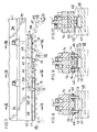
- Fig. 1 is a side elevation showing the running rail and self-propelled carrier of a conveyor embodying the invention;
- Fig. 2 is a front view of the same;
- Fig. 3 is an enlarged view in section taken along the line III-III in Fig. 1;
- Fig. 4 is an enlarged side elevation of a second drive trolley;
- Fig. 5 is a view in section taken along the line V-V in Fig. 4;
- Fig. 6 is a view in section taken along the line VI-VI in Fig. 4;
- Fig. 7 is an enlarged side elevation of a transit portion of the rail between a first high-speed running portion and a first low-speed running portion;
- Fig. 8 is a view in section taken along the line XIII-XIII in Fig. 7;
- Fig. 9 is a view in section taken along the line IX-IX in Fig. 7;
- Fig. 10 is a view in section taken along the line X-X in Fig. 7;
- Fig. 11 is an enlarged side elevation showing a portion of transit from the first low-speed running portion of the rail to a descent portion thereof;
- Fig. 12 is a view in section taken along the line XII-XII in Fig. 11;
- Fig. 13 is a view in section taken along the line XIII-XIII in Fig. 11;
- Fig. 14 is an enlarged side elevation showing a portion of transit from the descent portion of the rail to a low horizontal portion thereof;
- Fig. 15 is a view in section taken along the line XV-XV in Fig. 14; and
- Fig. 16 is a fragmentary side elevation schematically showing the rail.
- Figs. 1 and 2 show an example of running
rail 1 of a conveyor provided for a motor vehicle production line and an example of self-propelledcarrier 2 thereof. Figs. 3 to 15 show the same in detail. Fig. 16 is a fragmentary view showing the runningrail 1. In these drawings, the direction of advance of thecarrier 2 is indicated by arrows. In the following description, the terms "front," "rear," "right" and "left" are used with respect to the direction of advance of thecarrier 2. - With reference to Fig. 16, the running
rail 1 has a first high horizontal portion 3, a lowhorizontal portion 4 ahead thereof, and a second highhorizontal portion 5 futher ahead of theportion 4. Adescent portion 6 is provided at a portion of transit from the first high horizontal portion 3 to the lowhorizontal portion 4, and anascent portion 7 as a portion of transit from the lowhorizontal portion 4 to the second highhorizontal portion 5. The high horizontal portion 3 is divided into a high-speed running portion (first high-speed running portion) 3k in the rear, and a low-speed running portion (first low-speed running portion) 3t in the front. The second highhorizontal portion 5 is divided into a rearward low-speed running portion (second low-speed running portion) 5t and a forward high-speed running portion (second high-speed running portion) 5k. - As seen in detail in Figs. 3 to 5, the running
rail 1 is I-shaped in cross section and comprises anupper flange 1a,lower flange 1b andweb 1c interconnecting the flanges. The runningrail 1 is supported at suitable portions by unillustrated support members on the ceiling or the like of a building. On one side of theweb 1c of the runningrail 1 between the upper andlower flanges power distribution rail 9 is provided which has a plurality ofelectric wires 8 as arranged one above another. - Fig. 7 shows the portion of transit from the first high-speed running
portion 3k of therail 1 to the first low-speed runningportion 3t, Fig. 11 shows the portion of transit from the first low-speed runningportion 3t to thedescent portion 6, and Fig. 14 shows the portion of transit from thedescent portion 6 to the lowhorizontal portion 4. - As shown in detail in Figs. 7 to 15, an
auxiliary rail 10 is secured to the underside of thelower flange 1b of the runningrail 1 in the first low-speed runningportion 3t,descent portion 6, lowhorizontal portion 4,ascent portion 7 and second low-speed runningportion 5t. Theauxiliary rail 10 has an approximately rectangular cross section which is elongated transversely of therail 10. The lower surface of the widthwise midportion of therail 10 is in parallel to the lower surface of thelower flange 1b. - As seen in detail in Figs. 7 to 12, a
friction rail 11 rectangular in cross section is secured to the lower surface of the midportion of theauxiliary rail 10 in the first low-speed runningportion 3t. Further as shown in detail in Figs. 14 and 15, likefriction rail 12 is secured to the midportion lower surface of theauxiliary rail 10 at the lowhorizontal portion 4. As shown schematically in Fig. 16, likefriction rail 48 is also secured to the midportion lower surface of theauxiliary rail 10 at the second low-speed runningportion 5t. Thefriction rails auxiliary rail 10. - As shown in detail in Figs. 7 to 9, the rear end portion of the
auxiliary rail 10 at the transit portion between the first high-speed runningportion 3k and the first low-speed runningportion 3t provides aratchet pawl portion 49. At the right and left opposite sides of thisportion 49, a plurality ofratchet pawls 13 are supported each by atransverse pin 14 pivotally movably forward or rearward and are arranged at a spacing longitudinally of therail 10. Theratchet pawls 13 usually hang down under gravity and are at rest as projected downward beyond the lower surface of therail 10. Thepawls 13 in this state will not pivotally move even when a rearward force acts thereon but move forwardly upward when subjected to a forward force. No friction rail is provided beneath the auxiliary rail at the portion where theratchet pawls 13 are provided. Instead of the friction rail, awedgelike rail 15 is provided which extends from the rear end of thefriciton rail 11 at the first low-speed running portion 3t. At the front end, the thickness of thewedgelike rail 15 is equal to that of thefriction rail 11 but gradually decreases rearward. - With reference to Figs. 11 and 12, the
auxiliary rail 10 at the portion of transit from the first low-speed running portion 3t to thedescent portion 6 is in the form of aroller rack portion 51. At opposite sides of theroller rack portion 51, a plurality ofdownward teeth 16 are formed which are arranged at a spacing longitudinally of the rack portion. Eachtooth 16 has a transfersehorizontal roller 17. Awedgelike rail 18 extending from thefriction rail 11 is secured to the midportion lower surface of theauxiliary rail 10, in corresponding relation with therollers 17. At the rear end, the thickness of therail 18 is the same as that of thefriction rail 11 but gradually decreases toward the front. - With reference to Figs. 11 to 15, a
rack 20 havingdownward teeth 19 is formed at opposite sides of theauxiliary rail 10 at thedescent portion 6, integrally with therail 10. The rear end of therack 20 is continuous with theroller rack portion 51. - As seen in detail in Figs. 14 and 15, a
short rack 21 similar to and continuous with therack 20 is formed at opposite sides of theauxiliary rail 10 at the portion of transit from thedescent portion 6 to the lowhorizontal portion 4. Awedgelike rail 22 continuous with the rear end of thefriction rail 12 at the lowhorizontal portion 4 is secured to the midportion lower surface of theauxiliary rail 10, in corresponding relation with therack 21. Therail 22 is similar to thewedgelike rail 15. - The portion of transit from the low
horizontal portion 4 to theascent portion 7 is similar to the portion of transit from the first low-speed running portion 3t to thedescent portion 6. The portion of transit from theascent portion 7 to the second low-speed running portion 5t is similar to the portion of transit from thedescent portion 6 to the lowhorizontal portion 4. - The
carrier 2 has an intermediatefirst drive trolley 23, a frontsecond drive trolley 24, a rear driventrolley 25, andhangers 26 provided between and suspended from thefirst drive trolley 23 and the driventrolley 25. Thehangers 26 are each provided with asupport frame 27 for placing thereon motor vehicle parts or like article A to be transported. Thetrolleys front frames rear frames rail 1, and frames 23c, 24c, 25c interconnecting the lower portions of the front and rear frames, respectively. Thefirst drive trolley 23 is connected to thesecond drive trolley 24 by a connectingmember 28 in the form of a bar. Acontroller 29 for controlling the running of the carrier is attached to the connectingmember 28. Thecarrier 2 can be flexed upward, downward, rightward or leftward at the joint portions of thehangers 26 and the connectingmember 28. - With reference to Figs. 4 and 5, each of the
rear frame 23b of thefirst drive trolley 23, the front andrear frames second drive trolley 24, and the front andrear frames wheel 30 rollable on the upper surface of theupper flange 1a of the runningrail 1, and with oppositeupper wheels 31 disposed on opposite sides of theupper flange 1a for preventing horizontal deflection. Each of these frames is further provided at its lower portion with oppositelower wheels 32 arranged on opposite sides of thelower flange 1b of therail 1 for preventing horizontal deflection. - As shown in detail in Fig. 3, the
front frame 23a of thefirst drive trolley 23 is provided with a verticalfirst drive wheel 33 rollable on the upper surface of theupper flange 1a of the runningrail 1 and has, like the above trolly frames,upper wheels 34 andlower wheels 35 for preventing horizontal deflection. A firstelectric motor 36 for high-speed running is attached as directed upward to one side of thefront frame 23a and is coupled to thefirst drive wheel 33 by aclutch assembly 37, which although not shown, includes a clutch and a brake. Thefront frame 23a is provided with acurrent collector 38 opposed to thepower distribution rail 9. Thecollector 38 has a plurality ofcollector members 39 arranged one above another and held in sliding contact with the respectiveelectric wires 8 by suitable known means. Power and control signals are fed to thecontroller 29 from theelectric wires 8 via thecollector members 39. - With reference to Figs. 4 to 6, a
bracket 40 is attached to the connectingframe 24c of thesecond drive trolley 24. Thebracket 40 is pivotally movable upward or downward within a given range about a transversehorizontal pin 41 and is biased upward by aspring 42. Thebracket 40 has attached thereto a secondelectric motor 43 for running at a low speed and at the gradient portions. Thismotor 43 is disposed horizontally transversely of the runningrail 1 and has asecond drive wheel 45 secured to itsmotor shaft 44. Thedrive wheel 45 is integrally formed at its opposite sides withgears 46 having a larger diameter than the other portion of thewheel 45 and has fixed to the midportion of its outer surface afriction roller 47. Thefriction roller 47 is adapted to be pressed into contact with the lower surface of the friction rails 11, 12 by thespring 42. At the portions where the friction rails 11, 12 are absent, thefriction roller 47 will not contact theauxiliary rail 10 even if thebracket 40 is pivotally moved to its upper limit position. Further whereever thebracket 40 is positioned, thegears 46 will not interfere with the friction rails 11, 12, but are meshable with theratchet pawls 13, therollers 17 and theteeth 19 of theracks - With the conveyor described above, the
first drive wheel 33 causes thecarrier 2 to run at a high speed at the first high-speed running portion 3k and the second high-speed running portion 5k. Thesecond drive wheel 45 drives the carrier at a low speed at the first low-speed running portion 3t,descent portion 6, lowhorizontal portion 4,ascent portion 7 and second low-speed running portion 5t. - This will be described in order in detail.
- At the first high-
speed running portion 3k, thesecond motor 43 is at rest, and thefirst motor 36 is driven, with theclutch assembly 37 therefor engaged. Consequently, thefirst drive wheel 33 is driven, causing the carrier to run along therail 1. - When the
carrier 2 in this state reaches the portion of transit to the first low-speed running portion 3t, thegears 46 of thesecond drive wheel 45 collide withratchet pawls 13 as indicated in a phantom line S8 in Fig. 7 and as shown in Fig. 8. Upon the collision of thegears 46, thesepawls 13 pivotally move forwardly upward and escape, but upon the passage of the colliding teeth of thegears 46, thepawls 13 hand down again under gravity. When thesecond drive wheel 33 reaches the portion ofratchet pawls 13, thefirst motor 36 stops, and theclutch assembly 37 is disengaged, rendering thefirst drive wheel 33 free. At the same time, thesecond motor 43 is brought into rotation. Thesecond drive wheel 45 therefore rotates clockwise in Fig. 7, permitting thegears 46 to mesh withratchet pawls 13, whereby thegears 46 are subjected to a forward force to thereby advance thecarrier 2. When thecarrier 2 has advanced to an extent, thefriction roller 47 on thesecond drive wheel 45 comes into contact with the lower surface of an intermediate portion of thewedgelike rail 15 as indicated in a phantom line S9 in Fig. 7 and as shown in Fig. 9. The meshing engagement of thegears 46 withratchet pawls 13 further advances thecarrier 2, with thefriction roller 47 in contact with thewedgelike rail 15. Eventually, thefriction roller 47 leaves therail 15 and comes into contact with thefriction rail 11, while thegears 46 leaves theratchet pawls 13 as indicated in a phantom line S10 in Fig. 7 and as shown in Fig. 10. Thecarrier 2 runs along the runningrail 1 at the low speed in this state by virtue of the rotation of thefriction roller 47. - In the above mode of running, the
ratchet pawls 13 provided serve to mitigate the impact resulting from the collision of thegears 46, while the meshing engagement of thegears 46 with the ratchet pawls 13 advances thesecond drive wheel 45 to properly bring thefriction roller 47 into contact with thefriction rail 11. Since thefriction roller 47 is driven by the low-speed runningsecond motor 43, there is no likelihood of the drive torque becoming insufficient. - Upon the
carrier 2 reaching the portion of transit to thedescent portion 6 after running along the first low-speed running portion 3t, thefriction roller 47 on thesecond drive wheel 45 moves from thefriction rail 11 to thewedgelike rail 18, and thegears 46 meshes with therollers 17 of theroller rack portion 51 to thereby advance thecarrier 2 as indicated in a phantom line S12 in Fig. 11 and as shown in Fig. 12. When thecarrier 2 has advanced to an extent, thefriction roller 47 leaves thewedgelike rail 18, and in the meantime, thegears 46 come into meshing engagement with therack 20 after leaving therollers 17. The engagement of thegears 46 with therack 20 causes thecarrier 2 to run at a low speed along the runningrail 1 at thedescent portion 6 as indicated in a phantom line S13 in Fig. 11 and as shown in Fig. 13. - In the above process, the
rollers 17 provided upstream from therack 20 permit thegears 46 to mesh with therack 20 smoothly. Further since the meshing engagement of the gears with therack 20 drives thecarrier 2 along thedescent portion 6, thecarrier 2 is unlikely to slip. Thegears 46 mesh with thedownward teeth 19 of therack 20, while thefirst drive wheel 33 and the drivenwheels 30 bear the weight of thecarrier 2. This assures smooth engagement between thegears 46 and therack 20 and diminishes the wear that would occur. - Upon the
carrier 2 reaching the portion of transit to the lowhorizontal portion 4 after running along thedescent portion 6, thefriction roller 47 comes into contact with thewedgelike rail 22, and thegears 46 mesh with therack 21 as indicated in a phantom line S15 in Fig. 14 and as seen in Fig. 15. This enables thefriction roller 47 to leave therail 22 and come into contact with thefriction rail 12 properly. As is the case with the first low-speed running portion 3t, thefriction roller 47 causes thecarrier 2 to run at a low speed. - The carrier travels along the portion of transit from the low
horizontal portion 4 to theascent portion 7 in the same manner as already described with reference to Figs. 11 to 13. - At this time, the meshing engagment of the
gears 46 with therack 20 causes thecarrier 2 to run along theascent portion 7. This prevents thecarrier 2 from slipping. - The carrier travels along the portion of transit from the
ascent portion 7 to the second low-speed running portion 5t in the same manner as already described with reference to Figs. 14 and 15. - Upon the
carrier 2 reaching the portion of transit to the second high-speed running portion 5k after running along the second low-speed running portion 5t, there is nofriction rail 48 for theroller 47 to roll on, and thesecond motor 43 stops. At the same time, thefirst motor 36 is driven, and theclutch assembly 37 is engaged. Thefirst drive wheel 33 therefore rotates, causing thecarrier 2 to run along the second high-speed running portion 5k. - Although the
carrier 2 is adapted to run at a low speed along the entire lowhorizontal portion 4 according to the embodiment described, thisportion 4 may be divided into a low-speed running portion at opposite ends and an intermediate high-speed running portion.
Claims (1)
- A conveyor comprising a plurality of self-propelled carriers (2) adapted to run along a rail (1), the rail (1) having a first drive wheel bearing surface facing upward and a plurality of downward teeth (19) formed at least at a gradient portion (6, 7) of the rail (1), each of the carriers (2) having a first drive wheel (33) rollable on the wheel bearing surface of the rail (1), a first electric motor (36) for driving the first drive wheel (33) and a gear (46) meshable with the teeth (19) of the rail (1), characterized in that a second motor (43) is provided for driving the gear (46) and the rail (1) is formed at a required portion (3t, 4, 5t) with a friction roller bearing surface facing downward, and each of the carriers (2) has a friction roller (47) positionable in pressing contact with the roller bearing surface from below and rotatable by the second electric motor (43).
Applications Claiming Priority (2)
| Application Number | Priority Date | Filing Date | Title |
|---|---|---|---|
| JP1011300A JP2709619B2 (en) | 1989-01-19 | 1989-01-19 | Carrier self-propelled conveyor |
| JP11300/89 | 1989-01-19 |
Publications (3)
| Publication Number | Publication Date |
|---|---|
| EP0379206A2 EP0379206A2 (en) | 1990-07-25 |
| EP0379206A3 EP0379206A3 (en) | 1991-03-27 |
| EP0379206B1 true EP0379206B1 (en) | 1994-07-13 |
Family
ID=11774146
Family Applications (1)
| Application Number | Title | Priority Date | Filing Date |
|---|---|---|---|
| EP90101035A Expired - Lifetime EP0379206B1 (en) | 1989-01-19 | 1990-01-18 | Conveyor having self-propelled carrier |
Country Status (7)
| Country | Link |
|---|---|
| US (1) | US5174217A (en) |
| EP (1) | EP0379206B1 (en) |
| JP (1) | JP2709619B2 (en) |
| KR (1) | KR0149176B1 (en) |
| AU (2) | AU631172B2 (en) |
| CA (1) | CA2008023C (en) |
| DE (1) | DE69010515T2 (en) |
Cited By (1)
| Publication number | Priority date | Publication date | Assignee | Title |
|---|---|---|---|---|
| CN109775562A (en) * | 2019-01-27 | 2019-05-21 | 李楠 | A kind of whole line drive control structure of trolley cam friction driving |
Families Citing this family (15)
| Publication number | Priority date | Publication date | Assignee | Title |
|---|---|---|---|---|
| JP2509486Y2 (en) * | 1989-07-31 | 1996-09-04 | 中西金属工業株式会社 | Carrier self-propelled conveyor |
| ES2038910B1 (en) * | 1991-09-30 | 1995-05-01 | Nakanishi Metal Works Co | CONTROL SYSTEM OF THE RUNNING SPEED OF A SELF-PROPELLED VEHICLE. |
| IT1255806B (en) * | 1992-08-07 | 1995-11-16 | Giorgio Deandrea | SUSPENDED RAIL TRANSPORT SYSTEM |
| US6557676B2 (en) | 2001-01-23 | 2003-05-06 | Daimlerchrysler Rail Systems (Technology) | Innovia vehicle lock-on device |
| US7467723B2 (en) * | 2005-03-18 | 2008-12-23 | Zaguroli Jr James | Electric motor driven traversing balancer hoist |
| KR100791524B1 (en) | 2005-09-28 | 2008-01-04 | (주)영광산업개발 | Prefab bogie for repair and reinforcement of water and drainage |
| JP4976774B2 (en) * | 2006-07-28 | 2012-07-18 | Ihi運搬機械株式会社 | Overhead traveling crane |
| JP5206035B2 (en) * | 2008-03-11 | 2013-06-12 | 中西金属工業株式会社 | Conveyor vehicle travel device corresponding to inclined path |
| CN104003303B (en) * | 2014-05-14 | 2016-02-24 | 昆明理工大学 | A kind of track lifting shuttle |
| DE102015003736A1 (en) * | 2015-03-21 | 2016-09-22 | Eisenmann Se | Transport trolley and equipment for transporting objects |
| DE102015111124A1 (en) | 2015-05-08 | 2016-11-10 | AFT Automatisierungs- und Fördertechnik GmbH & Co. KG | Mechanical-electric drive |
| US10526030B2 (en) * | 2016-05-10 | 2020-01-07 | The Hi-Tech Robotic Systemz Ltd. | Climb structure for a robot |
| CN108382979B (en) * | 2018-02-23 | 2019-12-17 | 安徽江淮汽车集团股份有限公司 | Automatic switching system for lifting appliance |
| CA3039328A1 (en) * | 2018-04-06 | 2019-10-06 | Sst Systems, Inc. | Conveyor system with automated carriers |
| CN111284508A (en) * | 2020-04-14 | 2020-06-16 | 辽宁鑫丰矿业(集团)有限公司 | Motor-driven tractor |
Family Cites Families (23)
| Publication number | Priority date | Publication date | Assignee | Title |
|---|---|---|---|---|
| US601296A (en) * | 1898-03-29 | Of car wheels upon grades | ||
| US569097A (en) * | 1896-10-06 | fryer | ||
| DE229383C (en) * | ||||
| US1704958A (en) * | 1926-01-11 | 1929-03-12 | Bbc Brown Boveri & Cie | Electric railway system |
| US3033152A (en) * | 1958-01-27 | 1962-05-08 | Tourneau Robert G Le | Canal towing apparatus |
| US3356040A (en) * | 1964-05-11 | 1967-12-05 | Borgs Fabriks Ab | Device for conveyor systems |
| US3429280A (en) * | 1966-04-01 | 1969-02-25 | Dashaveyor Co | Rack and pinion vehicle propulsion system |
| FR1490620A (en) * | 1966-06-20 | 1967-08-04 | Noirot Et Fils Et Cie | Improvements to suspended air carriers |
| DE1755926A1 (en) * | 1968-07-11 | 1972-01-05 | Sybron Corp | Undercarriage for overhead tracks |
| US3648617A (en) * | 1969-08-11 | 1972-03-14 | Security Pacific National Bank | Resilient gripping railway traction system |
| DE2153185A1 (en) * | 1971-10-26 | 1973-05-03 | Messerschmitt Boelkow Blohm | ARRANGEMENT FOR MEASURING AND REGULATING SAFETY DISTANCES IN TRACK-MOUNTED VEHICLES |
| JPS4937892U (en) * | 1972-07-06 | 1974-04-03 | ||
| DE2343502A1 (en) * | 1973-08-29 | 1975-04-03 | Demag Ag | CAT MOVING ON A CARRIER |
| DE2545907C3 (en) * | 1975-10-14 | 1983-11-17 | Mannesmann AG, 4000 Düsseldorf | Conveyor track with a trolley guided on a rail |
| JPS5297575A (en) * | 1976-02-10 | 1977-08-16 | Nissei Ltd | Truck climbing device in transslift and monorail transportation system |
| JPS5297573A (en) * | 1976-02-10 | 1977-08-16 | Nissei Ltd | Truck climbing device in transslift and monorail transportation system |
| LU78204A1 (en) * | 1977-09-29 | 1979-05-25 | Bleichert Foerderanlagen Gmbh | MONORAIL CONVEYOR |
| IT1172886B (en) * | 1978-04-07 | 1987-06-18 | Fata Spa Ora Fata Europ Group | SINGLE RAIL AIR TRANSPORT DEVICE |
| US4428298A (en) * | 1981-12-14 | 1984-01-31 | Si Handling Systems, Inc. | Vehicle speed control transition module |
| DE3243914A1 (en) * | 1982-11-25 | 1984-05-30 | Siemens AG, 1000 Berlin und 8000 München | CHASSIS OF A CONVEYOR TROLLEY RUNNING ON PROFILE RAILS |
| DE3403460A1 (en) * | 1984-02-01 | 1985-08-08 | Georg 8200 Rosenheim Uttscheid | ELECTRIC RAILWAY |
| US4628823A (en) * | 1984-06-04 | 1986-12-16 | Si Handling Systems, Inc. | Vehicle speed control transition module and method |
| GB2162137B (en) * | 1984-06-18 | 1988-07-20 | Daifuku Kk | Conveying system |
-
1989
- 1989-01-19 JP JP1011300A patent/JP2709619B2/en not_active Expired - Fee Related
-
1990
- 1990-01-17 KR KR1019900000503A patent/KR0149176B1/en not_active Expired - Lifetime
- 1990-01-18 EP EP90101035A patent/EP0379206B1/en not_active Expired - Lifetime
- 1990-01-18 US US07/466,792 patent/US5174217A/en not_active Expired - Lifetime
- 1990-01-18 CA CA002008023A patent/CA2008023C/en not_active Expired - Lifetime
- 1990-01-18 DE DE69010515T patent/DE69010515T2/en not_active Expired - Fee Related
- 1990-01-19 AU AU48687/90A patent/AU631172B2/en not_active Ceased
- 1990-01-19 AU AU48686/90A patent/AU630918B2/en not_active Ceased
Cited By (2)
| Publication number | Priority date | Publication date | Assignee | Title |
|---|---|---|---|---|
| CN109775562A (en) * | 2019-01-27 | 2019-05-21 | 李楠 | A kind of whole line drive control structure of trolley cam friction driving |
| CN109775562B (en) * | 2019-01-27 | 2020-03-24 | 李楠 | Whole line drive control structure of trolley cam friction drive |
Also Published As
| Publication number | Publication date |
|---|---|
| EP0379206A2 (en) | 1990-07-25 |
| JP2709619B2 (en) | 1998-02-04 |
| AU630918B2 (en) | 1992-11-12 |
| CA2008023A1 (en) | 1990-07-19 |
| KR0149176B1 (en) | 1998-10-15 |
| DE69010515D1 (en) | 1994-08-18 |
| EP0379206A3 (en) | 1991-03-27 |
| AU4868690A (en) | 1990-07-26 |
| CA2008023C (en) | 2001-07-03 |
| AU631172B2 (en) | 1992-11-19 |
| US5174217A (en) | 1992-12-29 |
| JPH02193889A (en) | 1990-07-31 |
| KR900011654A (en) | 1990-08-01 |
| AU4868790A (en) | 1990-07-26 |
| DE69010515T2 (en) | 1994-11-24 |
Similar Documents
| Publication | Publication Date | Title |
|---|---|---|
| US5174217A (en) | Conveyor having self-propelled carriers with a first motor for high speed driving and a second motor for low speed driving | |
| EP0411517B1 (en) | Conveyor having self-propelled carriers | |
| US5069141A (en) | Overhead conveyor which provides increased reactive force and traction to drive wheel on ascending rail sections | |
| US5839567A (en) | Conveying system | |
| KR0147083B1 (en) | Accelerated Moving Walkway | |
| CA2010459C (en) | Electric overhead trolley system | |
| JPH0725441A (en) | Conveying installation using movable body | |
| JP3521545B2 (en) | Transfer equipment using movable bodies | |
| US6050196A (en) | Storage conveyor system for carrier car | |
| JP4081939B2 (en) | Transport device | |
| JPH061419A (en) | Movable body carrier device | |
| JPH0725440A (en) | Conveying installation using movable body | |
| EP0582348B1 (en) | Suspended rail conveyance system | |
| JP2963624B2 (en) | Structure to prevent displacement of traverser loading cart | |
| JPH07317366A (en) | Fork type multistory parking device | |
| JP4052173B2 (en) | Transportation equipment using moving objects | |
| US4595092A (en) | Load-pusher assembly for conveyor systems | |
| JP2741282B2 (en) | Truck transport device | |
| JPH0813641B2 (en) | Transport device using self-propelled body | |
| JP3382679B2 (en) | Acceleration / deceleration type moving sidewalk | |
| JPH02306873A (en) | Heavy load conveyor device | |
| JPH0139382B2 (en) | ||
| JPH0733009A (en) | Conveyance equipment with movable element | |
| JPH07317367A (en) | Fork type multistory parking device | |
| SU565854A1 (en) | Floor-mounted conveyor system |
Legal Events
| Date | Code | Title | Description |
|---|---|---|---|
| PUAI | Public reference made under article 153(3) epc to a published international application that has entered the european phase |
Free format text: ORIGINAL CODE: 0009012 |
|
| AK | Designated contracting states |
Kind code of ref document: A2 Designated state(s): DE FR GB IT |
|
| PUAL | Search report despatched |
Free format text: ORIGINAL CODE: 0009013 |
|
| AK | Designated contracting states |
Kind code of ref document: A3 Designated state(s): DE FR GB IT |
|
| 17P | Request for examination filed |
Effective date: 19910802 |
|
| 17Q | First examination report despatched |
Effective date: 19930427 |
|
| GRAA | (expected) grant |
Free format text: ORIGINAL CODE: 0009210 |
|
| AK | Designated contracting states |
Kind code of ref document: B1 Designated state(s): DE FR GB IT |
|
| REF | Corresponds to: |
Ref document number: 69010515 Country of ref document: DE Date of ref document: 19940818 |
|
| ITF | It: translation for a ep patent filed | ||
| ET | Fr: translation filed | ||
| PLBE | No opposition filed within time limit |
Free format text: ORIGINAL CODE: 0009261 |
|
| STAA | Information on the status of an ep patent application or granted ep patent |
Free format text: STATUS: NO OPPOSITION FILED WITHIN TIME LIMIT |
|
| 26N | No opposition filed | ||
| PGFP | Annual fee paid to national office [announced via postgrant information from national office to epo] |
Ref country code: FR Payment date: 19951116 Year of fee payment: 7 |
|
| PG25 | Lapsed in a contracting state [announced via postgrant information from national office to epo] |
Ref country code: FR Effective date: 19970930 |
|
| REG | Reference to a national code |
Ref country code: FR Ref legal event code: ST |
|
| REG | Reference to a national code |
Ref country code: GB Ref legal event code: IF02 |
|
| PG25 | Lapsed in a contracting state [announced via postgrant information from national office to epo] |
Ref country code: IT Free format text: LAPSE BECAUSE OF NON-PAYMENT OF DUE FEES;WARNING: LAPSES OF ITALIAN PATENTS WITH EFFECTIVE DATE BEFORE 2007 MAY HAVE OCCURRED AT ANY TIME BEFORE 2007. THE CORRECT EFFECTIVE DATE MAY BE DIFFERENT FROM THE ONE RECORDED. Effective date: 20050118 |
|
| PGFP | Annual fee paid to national office [announced via postgrant information from national office to epo] |
Ref country code: GB Payment date: 20080123 Year of fee payment: 19 Ref country code: DE Payment date: 20071219 Year of fee payment: 19 |
|
| GBPC | Gb: european patent ceased through non-payment of renewal fee |
Effective date: 20090118 |
|
| PG25 | Lapsed in a contracting state [announced via postgrant information from national office to epo] |
Ref country code: DE Free format text: LAPSE BECAUSE OF NON-PAYMENT OF DUE FEES Effective date: 20090801 |
|
| PG25 | Lapsed in a contracting state [announced via postgrant information from national office to epo] |
Ref country code: GB Free format text: LAPSE BECAUSE OF NON-PAYMENT OF DUE FEES Effective date: 20090118 |