EP0378810B1 - Druckluftbremseinrichtung für Kraftfahrzeuge - Google Patents
Druckluftbremseinrichtung für Kraftfahrzeuge Download PDFInfo
- Publication number
- EP0378810B1 EP0378810B1 EP89123119A EP89123119A EP0378810B1 EP 0378810 B1 EP0378810 B1 EP 0378810B1 EP 89123119 A EP89123119 A EP 89123119A EP 89123119 A EP89123119 A EP 89123119A EP 0378810 B1 EP0378810 B1 EP 0378810B1
- Authority
- EP
- European Patent Office
- Prior art keywords
- valve
- trailer
- brake
- conduit
- control
- Prior art date
- Legal status (The legal status is an assumption and is not a legal conclusion. Google has not performed a legal analysis and makes no representation as to the accuracy of the status listed.)
- Revoked
Links
- 238000009434 installation Methods 0.000 title 1
- 230000008901 benefit Effects 0.000 description 5
- 230000008878 coupling Effects 0.000 description 2
- 238000010168 coupling process Methods 0.000 description 2
- 238000005859 coupling reaction Methods 0.000 description 2
- 230000004044 response Effects 0.000 description 2
- 238000009825 accumulation Methods 0.000 description 1
- 230000009471 action Effects 0.000 description 1
- 230000004913 activation Effects 0.000 description 1
- 230000004048 modification Effects 0.000 description 1
- 238000012986 modification Methods 0.000 description 1
- 230000009467 reduction Effects 0.000 description 1
- 230000000717 retained effect Effects 0.000 description 1
- 238000009423 ventilation Methods 0.000 description 1
Images


Classifications
-
- B—PERFORMING OPERATIONS; TRANSPORTING
- B60—VEHICLES IN GENERAL
- B60T—VEHICLE BRAKE CONTROL SYSTEMS OR PARTS THEREOF; BRAKE CONTROL SYSTEMS OR PARTS THEREOF, IN GENERAL; ARRANGEMENT OF BRAKING ELEMENTS ON VEHICLES IN GENERAL; PORTABLE DEVICES FOR PREVENTING UNWANTED MOVEMENT OF VEHICLES; VEHICLE MODIFICATIONS TO FACILITATE COOLING OF BRAKES
- B60T7/00—Brake-action initiating means
- B60T7/12—Brake-action initiating means for automatic initiation; for initiation not subject to will of driver or passenger
- B60T7/20—Brake-action initiating means for automatic initiation; for initiation not subject to will of driver or passenger specially for trailers, e.g. in case of uncoupling of or overrunning by trailer
-
- B—PERFORMING OPERATIONS; TRANSPORTING
- B60—VEHICLES IN GENERAL
- B60T—VEHICLE BRAKE CONTROL SYSTEMS OR PARTS THEREOF; BRAKE CONTROL SYSTEMS OR PARTS THEREOF, IN GENERAL; ARRANGEMENT OF BRAKING ELEMENTS ON VEHICLES IN GENERAL; PORTABLE DEVICES FOR PREVENTING UNWANTED MOVEMENT OF VEHICLES; VEHICLE MODIFICATIONS TO FACILITATE COOLING OF BRAKES
- B60T13/00—Transmitting braking action from initiating means to ultimate brake actuator with power assistance or drive; Brake systems incorporating such transmitting means, e.g. air-pressure brake systems
- B60T13/10—Transmitting braking action from initiating means to ultimate brake actuator with power assistance or drive; Brake systems incorporating such transmitting means, e.g. air-pressure brake systems with fluid assistance, drive, or release
- B60T13/66—Electrical control in fluid-pressure brake systems
Definitions
- the invention relates to an air brake device for motor vehicles according to the preamble of the main claim.
- a compressed air brake device is known (DE-OS 36 03 963).
- the sensor-controlled correction valve engages in the trailer brake line in order to vary the trailer brake pressure accordingly.
- the trailer brake line in a two-line brake system is used to transmit the brake signal to the trailer brake valve, the trailer brake line must always be free in an emergency. Therefore, such an intervention in the trailer brake line has the disadvantage that if the correction valve is switched incorrectly, the trailer brake valve via the trailer brake line, e.g. is no longer convertible in the braking direction during a parking brake application.
- the air brake device mentioned at the outset has the advantage that the trailer brake line remains open for actuation of the trailer brake valve even when the correction valve is switched incorrectly. This creates an essential security factor.
- the overall dimensions of the trailer control valve can also be reduced, since the control pistons do not require such large active areas in order to have a corresponding response behavior.
- Response pressure and hysteresis can be electrically balanced.
- FIG. 1 shows a pressure medium brake device with a conventional trailer control valve
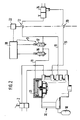
- FIG. 2 shows a pressure medium brake device with a conventional trailer brake valve and an activation of the correction valve
- FIG. 3 shows a variant of the pressure medium brake device according to FIG. 1.
- a pressure medium brake device has on a towing vehicle 1 a two-circuit service brake valve 2, which allows compressed air from two reservoirs 3 and 4 to enter a service brake circuit I and II, respectively.
- the brake circuit I controls a trailer control valve 6 with a pressure increase via a line 5.
- a second control line 7 is brought from a parking brake, not shown; with its pressure, the trailer control valve 6 can be switched over by a pressure drop in the braking direction.
- a third control line 8 on the trailer control valve 6 in turn serves to control the pressure rise. But it is not from the service brake valve 2 brought up, but from a correction valve 9 and receives its pressure from a trailer storage container 10 arranged on the towing vehicle 1.
- a throttle valve 13 flanged to the trailer control valve 6, which can be switched over by pressures from the lines shown in broken lines.
- a first branch 14 of the trailer supply line 11 leads to the trailer control valve 6 and a second branch 15 of the trailer supply line 11 leads to two solenoid valves 16 and 17 of the correction valve 9.
- the pulses for the solenoid valves 16 and 17 are generated by a control unit 18, which also leads to the correction valve 9 belongs.
- the control unit 18 is connected to a sensor 22 for the overrun forces between a trailer 23 coupled to the towing vehicle 1 and the towing vehicle 1.
- the trailer 23 has a conventional trailer brake system, of which only one trailer brake valve 24 is shown, however.
- the line 5 receives pressure in order to actuate the trailer control valve 6.
- the accumulation of the trailer 23 actuates the sensor 22, which gives a signal to the control unit 18.
- This energizes the two solenoid valves 16 and 17, causing the solenoid valves 16 and 17 to switch from the position shown to their respective other positions. So that the previously open outside air connection of line 8 of line 8 is closed and supply air from the storage container 10 is passed as control air to the trailer control valve 6; via the two solenoid valves 16 and 17 is therefore either supply pressure into line 8 or the latter is vented.
- By changing the valve opening or closing times of the two solenoid valves 16 and 17 practically any pressure between zero and the supply pressure can be controlled via the line 8 to the trailer control valve 6.
- the brake pressure in the trailer brake line 19 can then be varied accordingly.
- the control of the two solenoid valves 16 and 17 is influenced by the forces occurring on the mechanical connection device of the two vehicles 1 and 23.
- the pressure in the trailer brake line 19 cannot fall below the pressure which is controlled by the brake circuit I via the line 5, since in such a case the pressure in the line 5 automatically becomes the guide pressure.
- This variant works in such a way that the pressure in the trailer brake line 19 can be reduced below the pressure controlled by the service brake valve 2.
- line 5 is vented, so that the pressure introduced into line 8, which is lower than the pressure present at brake valve 2, can influence the pressure in trailer brake line 19.
- the 3/2-way solenoid valve 26 is controlled electrically, but it can also be controlled pneumatically.
- the version with a 3/2-way solenoid valve 26 is more complex than one without this valve, but it has the advantage that also a pulling trailer must be adapted to the braking condition of the towing vehicle by means of the required pressure reduction.
- the compressed air brake device can be optionally equipped with or without a 3/2-way valve.
- FIG. 2 shows a modification of the type according to FIG. 1.
- a conventional trailer control valve 30 is used, which is equipped with an additional switching piston 31.
- the pressure applied by the two solenoid valves 16 and 17 of the correction valve 9 can be applied to the trailer control valve 30.
- Such an embodiment has the advantage that the two-circuit control that is usual for a trailer control valve and originates from the two-circuit service brake valve 2 is fully retained, i.e. in the event of a power failure, two control circuits are always available.
- This two-way check valve 32 allows the higher incoming pressure from the service brake valve 2 or from the pressure control valve 16, 17 to reach the control chamber of the trailer control valve 6. This ensures that as long as no drawbar force occurs and the pressure control valve 16, 17 is on ventilation, that of the service brake valve 2 in both lines 5 and 5 'input pressure to the trailer control valve 6 is let through.
- the pressure control valve 16, 17 controlled by the sensor 22 via the control unit 18 controls a higher pressure than it comes from the service brake valve 2.
- the two-way check valve 32 then lets the higher pressure from the pressure control valve 16, 17 through to the trailer control valve 6 and shuts off from the service brake valve 2.
- the drawbar force is set to zero by the drawbar force control, i.e. the towing vehicle 1 cannot be additionally braked by a towing trailer 23.
Landscapes
- Engineering & Computer Science (AREA)
- Transportation (AREA)
- Mechanical Engineering (AREA)
- Braking Systems And Boosters (AREA)
Description
- Die Erfindung geht aus von einer Druckluftbremseinrichtung für Kraftfahrzeuge nach der Gattung des Hauptanspruches. Eine derartige Druckluftbremseinrichtung ist bekannt (DE-OS 36 03 963).
- Bei dieser bekannten Druckluftbremseinrichtung greift das sensorgesteuerte Korrekturventil in die Anhängerbremsleitung ein, um den Anhängerbremsdruck entsprechend zu variieren. Da aber die Anhängerbremsleitung bei einer Zweileitungsbremsanlage zur Bremssignalübermittlung an das Anhängerbremsventil dient, muß die Anhängerbremsleitung im Notfall immer frei sein. Deshalb hat ein solcher Eingriff in die Anhängerbremsleitung den Nachteil, daß bei einer Fehlschaltung des Korrekturventils das Anhängerbremsventil über die Anhängerbremsleitung, z.B. bei einem Feststellbremsvorgang nicht mehr im Bremssinn umstellbar ist.
- Die eingangs genannte Druckluftbremseinrichtung mit den kennzeichnenden Merkmalen des Hauptanspruches hat demgegenüber den Vorteil, daß die Anhängerbremsleitung auch bei einer Fehlschaltung des Korrekturventils für eine Ansteuerung des Anhängerbremsventils offen bleibt. Damit ist ein wesentlicher Sicherheitsfaktor geschaffen.
- Dazu kommt, daß eine vom Anhängersteuerventil in bisher üblicher Weise eingesteuerte Voreilschaltung der Anhängerbremse im Anhängersteuerventil jetzt entfallen kann; damit wird dieses Ventil einfacher im Aufbau.
- Schließlich kann auch die Gesamtabmessung des Anhängersteuerventils reduziert werden, da die Steuerkolben keine so großen Wirkflächen benötigen, um ein entsprechendes Ansprechverhalten aufzuweisen. Ansprechdruck und Hystere können elektrisch ausgeglichen werden.
- Drei Ausführungsbeispiele der Erfindung sind in der Zeichnung dargestellt und in der nachfolgenden Beschreibung näher erläutert. Es zeigen: Figur 1 eine Druckmittelbremseinrichtung mit einem herkömmlichen Anhängersteuerventil, Figur 2 eine Druckmittelbremseinrichtung mit herkömmlichem Anhängerbremsventil und einer Aufschaltung des Korrekturventils und Figur 3 eine Variante der Druckmittelbremseinrichtung nach Figur 1.
- Eine Druckmittelbremseinrichtung hat auf einem Zugwagen 1 ein zweikreisiges Betriebsbremsventil 2, das Druckluft aus zwei Vorratsbehältern 3 und 4 in je einen Betriebsbremskreis I und II gelangen läßt. Der Bremskreis I steuert über eine Leitung 5 ein Anhängersteuerventil 6 mit Druckanstieg. Eine zweite Steuerleitung 7 ist von einer nicht dargestellten Feststellbremse herangeführt; mit ihrem Druck kann das Anhängersteuerventil 6 durch Druckabfall im Bremssinn umgeschaltet werden.
- Eine dritte Steuerleitung 8 am Anhängersteuerventil 6 dient wiederum einer Druckanstiegssteuerung. Sie ist aber nicht von dem Betriebsbremsventil 2 herangeführt, sondern von einem Korrekturventil 9 und erhält ihren Druck aus einem auf dem Zugwagen 1 angeordneten Anhänger-Vorratsbehälter 10. In der Verbindung einer Anhängervorratsleitung 11 vom Vorratsbehälter 10 zu einem Vorratsluft-Kupplungskopf 12 liegt ein an das Anhängersteuerventil 6 angeflanschtes Drosselventil 13, das von Drücken aus den gestrichelt eingezeichneten Leitungen umschaltbar ist. Eine erste Abzweigung 14 der Anhängervorratsleitung 11 führt zum Anhängersteuerventil 6 und eine zweite Abzweigung 15 der Anhängervorratsleitung 11 führt zu zwei Magnetventilen 16 und 17 des Korrekturventils 9. Die Impulse für die Magnetventile 16 und 17 werden durch ein Steuergerät 18 erstellt, das ebenfalls zum Korrekturventil 9 gehört.
- Vom Anhängersteuerventil 6 nimmt eine Anhängerbremsleitung 19 ihren Ausgang, die zu einem Bremsleitungskupplungskopf 20 führt. Das Steuergerät 18 hat eine Verbindung mit einem Sensor 22 für die Auflaufkräfte zwischen einem mit dem Zugwagen 1 gekuppelten Anhänger 23 und dem Zugwagen 1.
- Der Anhänger 23 hat eine übliche Anhängerbremsanlage, von der im wesentlichen jedoch nur ein Anhängerbremsventil 24 dargestellt ist.
- Beim Betätigen des Betriebsbremsventils 2 erhält die Leitung 5 Druck, um das Anhängersteuerventil 6 anzusteuern. Durch das Auflaufen des Anhängers 23 wird der Sensor 22 betätigt, der ein Signal an das Steuergerät 18 gibt. Dieses bestromt die beiden Magnetventile 16 und 17, wodurch die Magnetventile 16 und 17 aus der gezeichneten Lage in ihre jeweils andere Stellung umschalten. Damit wird die vorher offene Außenluftverbindung der Leitung 8 der Leitung 8 geschlossen und Vorratsluft aus dem Vorratsbehälter 10 wird als Steuerluft zum Anhängersteuerventil 6 geleitet; über die beiden Magnetventile 16 und 17 wird also wahlweise Vorratsdruck in die Leitung 8 eingesteuert oder letztere wird entlüftet. Durch Veränderung der Ventilöffnungs- oder Schließzeiten der beiden Magnetventile 16 und 17 kann praktisch jeder beliebige Druck zwischen Null und dem Vorratsdruck über die Leitung 8 zum Anhängersteuerventil 6 eingesteuert werden. Damit ist dann der Bremsdruck in der Anhängerbremsleitung 19 entsprechend zu variieren.
- Die Ansteuerung der beiden Magnetventile 16 und 17 wird dabei von den an der mechanischen Verbindungseinrichtung der beiden Fahrzeuge 1 und 23 auftretenden Kräften beeinflußt.
- Jedoch kann bei dem Ausführungsbeispiel nach der Figur 1 der Druck in der Anhängerbremsleitung 19 nicht unter den Druck fallen, der vom Bremskreis I über die Leitung 5 eingesteuert wird, da in einem solchen Fall automatisch der Druck in der Leitung 5 zum Führungsdruck wird.
- Es ist auch möglich, in die Leitung 5 ein 3/2-Wege-Magnetventil 26 einzusetzen, wie es in der Figur 1 strichpunktiert dargestellt ist. Die Magnetseite dieses Magnetventils ist an das Steuergerät 18 angeschlossen.
- Diese Variante arbeitet derart, daß der Druck in der Anhängerbremsleitung 19 unter den vom Betriebsbremsventil 2 eingesteuerten Druck abgesenkt werden kann. Dazu wird die Leitung 5 entlüftet, so daß der in die Leitung 8 eingesteuerte Druck, der niedriger ist als der am Bremsventil 2 anstehende Druck, den Druck in der Anhängerbremsleitung 19 beeinflußen kann. Das 3/2-Wege-Magnetventil 26 wird elektrisch angesteuert, es kann aber auch pneumatisch gesteuert werden.
- Die Ausführung mit einem 3/2-Wege-Magnetventil 26 ist zwar aufwendiger als eine ohne dieses Ventil, sie hat aber den Vorteil, daß auch ein ziehender Anhänger mittels dann erforderlicher Druckabsenkung an den Bremszustand des Zugwagens anzupassen ist. Auf jeden Fall kann die Druckluftbremseinrichtung wahlweise baukastenartig mit oder ohne 3/2-Wege-Ventil ausgerüstet werden.
- Die Figur 2 zeigt eine Abwandlung der Bauart nach der Figur 1. Hier ist ein übliches Anhängersteuerventil 30 verwendet, das mit einem zusätzlichen Schaltkolben 31 ausgerüstet ist. Mittels dieses Schaltkolbens 31 kann der von den beiden Magnetventilen 16 und 17 des Korrekturventils 9 jeweils eingesteuerte Druck dem Anhängersteuerventil 30 aufgeschaltet werden.
- Eine solche Ausführung hat den Vorteil, daß die bei einem Anhängersteuerventil übliche, vom Zweikreis-Betriebsbremsventil 2 herrührende zweikreisige Ansteuerung voll erhalten bleibt, d.h. bei Stromausfall stehen auf jeden Fall zwei Ansteuerkreise zur Verfügung.
- Wenn die Bauart nach der Figur 2 so arbeiten soll, wie die Bauart nach der Figur 1 mit dem 3/2-Wege-Ventil, dann muß auch eine Kammer unter dem Schaltkolben 31 zur Steuerung mit herangezogen werden.
- Es ist auch möglich, in eine zweite vom Betriebsbremsventil 2 zum Anhängersteuerventil 6 geführte Leitung 5′ ein Zweiwege-Rückschlagventil 32 einzusetzen, dessen zweite Seite an die von der Anhängervorratsleitung abgezweigte, von dem Steuergerät 18 elektrisch angesteuerten Drucksteuerventil 16, 17 überwachte Steuerleitung 8 angeschlossen ist.
- Dieses Zweiwege-Rückschlagventil 32 läßt den vom Betriebsbremsventil 2 bzw. vom Drucksteuerventil 16, 17 jeweils höheren ankommenden Druck in die Steuerkammer des Anhängersteuerventils 6 gelangen. Damit ist erreicht, daß solange keine Deichselkraft auftritt und das Drucksteuerventil 16, 17 auf Entlüftung steht, der vom Betriebsbremsventil 2 in beiden Leitungen 5 und 5′ eingesteuerte Druck zum Anhängersteuerventil 6 durchgelassen wird.
- Schiebt nun der Anhänger 23 auf und ist deswegen ein höherer Bremsdruck im Anhänger 23 erforderlich, steuert das vom Sensor 22 über das Steuergerät 18 angesteuerte Drucksteuerventil 16, 17 einen höheren Druck ein als er vom Betriebsbremsventil 2 kommt. Das Zweiwege-Rückschlagventil 32 läßt dann den höheren Druck vom Drucksteuerventil 16, 17 zum Anhängersteuerventil 6 durch und sperrt zum Betriebsbremsventil 2 hin ab.
- Der Vorteil einer solchen Bauart liegt darin, daß bei Spannungsausfall zwei pneumatische Bremskreise zum Ansteuern des Anhängersteuerventils 6 zur Verfügung stehen.
- Dazu kommt, daß bei der zuerst beschriebenen Bauart bei Ausfall des 1. Bremskreises (Leitung) die Deichselkraft durch die Deichselkraftregelung auf Null gesetzt wird, d.h. das Zugfahrzeug 1 kann nicht durch einen ziehenden Anhänger 23 zusätzlich gebremst werden.
- Bei der zuletzt genannten Variante wirkt dagegen der volle Bremsdruck im Anhänger 23, da der Druck ja nicht unter den vom Betriebsbremsventil 2 in die Leitung 5′ eingesteuerten Druck fallen kann.
Claims (6)
- Druckluftbremseinrichtung für Kraftfahrzeuge (1, 23), mit mindestens einem durch ein Betriebsbremsventil (2) aussteuerbaren Betriebsbremssteuerkreis (I), einem den Druck in einer Anhängerbremsleitung (19) steuernden, an den Betriebsbremssteuerkeis (I) angeschlossenen Anhängersteuerventil (6) einer Zweileitungsbremsanlage mit einem über die Anhängerbremsleitung (19) und eine Anhängervorratsleitung (11) mit dem Anhängersteuerventil (6) verbundenen Anhängerbremsventil (24) und mit einem durch entsprechende, an einer mechanischen Verbindungseinrichtung des Kraftfahrzeuges (1, 23) mittels Sensor (22) gemessenen Kräfte steuerbaren Korrekturventil (9), welches in einer von der Anhängervorratsleitung (11) abgezweigten Steuerleitung (8) liegt, dadurch gekennzeichnet, daß der Druck in der zum Anhängersteuerventil (6) geführten Steuerleitung (8) durch das Korrekturventil (9) beeinflußbar ist, während die Anhängerbremsleitung (19) kein Sperrglied enthält.
- Druckluftbremseinrichtung nach Anspruch 1, dadurch gekennzeichnet, daß der von dem Korrekturventil (9) varriierte Vorratsdruck dem Anhängersteuerventil (6, 30) als Druckgröße zugeführt ist.
- Druckluftbremseinrichtung nach Anspruch 1, dadurch gekennzeichnet, daß bei Auslegung der Bremseinrichtung mit üblichem Anhängersteuerventil (30) der von dem Korrekturventil (9) beeinflußte Vorratsdruck dem Anhängersteuerventil (30) zusätzlich aufgeschaltet ist.
- Druckluftbremseinrichtung nach einem der Ansprüche 1 bis 3, dadurch gekennzeichnet, daß das Korrekturventil (9) zwei 2/2-Wege-Magnetventile (16, 17) aufweist, von denen eines ein in der Steuerleitung (8) angeordnetes Durchgangsventil ist und das andere ein an die Steuerleitung (8) angeschlossenes Außenluftventil ist.
- Druckluftbremseinrichtung nach einem der Ansprüche 1 bis 4, dadurch gekennzeichnet, daß in eine von einem Betriebsbremsventil (2) unmittelbar zu dem Anhängersteuerventil (6) geführte Leitung (5) ein 3/2-Wege-Ventil (26) eingesetzt ist, mit dem der anhängersteuerventilseitige Leitungsteil der Leitung (5) entlüftbar ist.
- Druckluftbremseinrichtung nach einem der Ansprüche 1 bis 4, dadurch gekennzeichnet, daß in eine (5′) der vom Betriebsbremsventil (2) zum Anhängersteuerventil (6) geführten Leitungen (5, 5′) ein Zweiwege-Rückschlagventil (32) eingesetzt ist, dessen zweite Seite an die von der Anhängervorratsleitung (11) abgezweigte Steuerleitung (8) angeschlossen ist.
Applications Claiming Priority (2)
| Application Number | Priority Date | Filing Date | Title |
|---|---|---|---|
| DE3901269 | 1989-01-18 | ||
| DE3901269A DE3901269A1 (de) | 1989-01-18 | 1989-01-18 | Druckluftbremseinrichtung fuer kraftfahrzeuge |
Publications (2)
| Publication Number | Publication Date |
|---|---|
| EP0378810A1 EP0378810A1 (de) | 1990-07-25 |
| EP0378810B1 true EP0378810B1 (de) | 1993-04-28 |
Family
ID=6372265
Family Applications (1)
| Application Number | Title | Priority Date | Filing Date |
|---|---|---|---|
| EP89123119A Revoked EP0378810B1 (de) | 1989-01-18 | 1989-12-14 | Druckluftbremseinrichtung für Kraftfahrzeuge |
Country Status (2)
| Country | Link |
|---|---|
| EP (1) | EP0378810B1 (de) |
| DE (2) | DE3901269A1 (de) |
Families Citing this family (11)
| Publication number | Priority date | Publication date | Assignee | Title |
|---|---|---|---|---|
| DE3936726A1 (de) * | 1989-11-04 | 1991-05-08 | Wabco Westinghouse Fahrzeug | Verfahren zur abbremsung eines mit druckbetaetigten bremsen ausgeruesteten fahrzeugzuges |
| SE467204B (sv) * | 1989-12-29 | 1992-06-15 | Saab Scania Ab | Arrangemang foer anpassning av bromstrycket i bromssystemet paa ett draget fordon till bromstrycket i bromssystemet paa ett dragande fordon |
| DE4226697C1 (de) * | 1992-08-12 | 1993-09-23 | Grau Gmbh, 69123 Heidelberg, De | |
| DE4230674C2 (de) * | 1992-09-14 | 1999-09-30 | Knorr Bremse Systeme | Druckluftbremse für Straßentriebfahrzeuge |
| US5390990A (en) * | 1993-11-24 | 1995-02-21 | Hydro-Aire Division Of Crane Company | Brake energy balancing system for multiple brake units |
| US5777218A (en) * | 1996-03-12 | 1998-07-07 | Hydro-Aire Division Of Crane Company | Monitor for uncommanded braking |
| US6722745B2 (en) | 1997-05-02 | 2004-04-20 | Hydro-Aire, Inc. | System and method for adaptive brake application and initial skid detection |
| US6132016A (en) | 1997-05-02 | 2000-10-17 | Hydro-Aire, Inc. | System and method for adaptive brake application and initial skid detection |
| US8249789B2 (en) | 2008-10-29 | 2012-08-21 | Bedix Commercial Vehicle Systems LLC | Spring brake valve |
| EP2891586B1 (de) | 2014-01-07 | 2017-06-21 | Unsinn Fahrzeugtechnik GmbH | Anhänger mit autarkem Druckluft-Bremssystem |
| GB202019737D0 (en) | 2020-12-15 | 2021-01-27 | Agco Int Gmbh | Trailer brake control system |
Family Cites Families (2)
| Publication number | Priority date | Publication date | Assignee | Title |
|---|---|---|---|---|
| DE2202676A1 (de) * | 1972-01-20 | 1973-07-26 | Linde Ag | Bremseinrichtung fuer einen von einem kraftfahrzeug gezogenen anhaenger |
| DE3603963A1 (de) * | 1986-02-07 | 1987-08-13 | Knorr Bremse Ag | Druckluftbremseinrichtung fuer kraftfahrzeugzuege |
-
1989
- 1989-01-18 DE DE3901269A patent/DE3901269A1/de not_active Ceased
- 1989-12-14 DE DE8989123119T patent/DE58904214D1/de not_active Revoked
- 1989-12-14 EP EP89123119A patent/EP0378810B1/de not_active Revoked
Also Published As
| Publication number | Publication date |
|---|---|
| DE58904214D1 (de) | 1993-06-03 |
| EP0378810A1 (de) | 1990-07-25 |
| DE3901269A1 (de) | 1990-07-19 |
Similar Documents
| Publication | Publication Date | Title |
|---|---|---|
| EP1188634B2 (de) | Anhängerbremsventil für Anhängefahrzeuge mit elektronischer Bremsregelung und erweiterter Sicherheit des geparkten Anhängers | |
| EP3600996B1 (de) | Integriertes anhängersteuermodul (tcv) mit externer elektropneumatischer handbremseinheit (eph) | |
| EP0883538B1 (de) | Anhängersteuerventil für eine druckluftbremsanlage für kraftfahrzeuge | |
| EP2059429B1 (de) | Ventileinheit für eine elektropneumatische bremssteuerungseinrichtung | |
| DE102017006356A1 (de) | Elektro-Pneumatische Handbremse (EPH) mit integriertem TCV (Europäische Ansteuerung) | |
| EP2238004A2 (de) | Parkbremse | |
| DE102007038472A1 (de) | Ventilanordnung zur Steuerung einer Bremsanlage eines Anhängerfahrzeugs | |
| EP3307594B1 (de) | Pneumatische bremsanlage für ein anhängefahrzeug | |
| EP0957018B1 (de) | Druckluftaufbereitungseinrichtung für Druckluftbeschaffungsanlagen auf Kraftfahrzeugen | |
| DE19918070B4 (de) | Druckregelvorrichtung für elektro-pneumatische Bremsanlagen von Fahrzeugen, insbesondere Nutzfahrzeugen | |
| DE19653264A1 (de) | Elektronisch steuerbares Bremssystem für Fahrzeuge, insbesondere Nutzfahrzeuge | |
| EP1133424A1 (de) | Park- und rangierventil für anhängefahrzeuge mit einer federspeicher-feststellbremse | |
| EP0278228A2 (de) | Elektro-pneumatische Bremsanlage für Zugfahrzeuge | |
| DE3545021C2 (de) | Elektro-pneumatische Bremsanlage | |
| EP0378810A1 (de) | Druckluftbremseinrichtung für Kraftfahrzeuge | |
| EP3507148A1 (de) | Pneumatische bremsanlage für ein anhängefahrzeug | |
| EP3112231A1 (de) | Feststellbremsmodul, bremsanlage und fahrzeug damit sowie verfahren zum betreiben einer feststellbremseinrichtung mit einem solchen modul | |
| DE20122549U1 (de) | Anhängerbremsventil für Anhängefahrzeuge mit elektronischer Bremsregelung und erweiterter Sicherheit des geparkten Anhängers | |
| EP0378811B1 (de) | Druckluftbremseinrichtung für Kraftfahrzeuge | |
| EP1914137A2 (de) | Anhängerbremsventil für Anhängefahrzeuge mit elektronischer Bremsregelung und erweiterter Sicherheit des geparkten Anhängers | |
| DE102018002488B4 (de) | Bremssystem eines Fahrzeugzuges | |
| DE10139748A1 (de) | Anhängerbremsventil für einen Anhänger mit elektronischer Bremsregelung | |
| DE2810219A1 (de) | Drucksteuerventil-aggregat ii | |
| DE20122779U1 (de) | Anhängerbremsventil für Anhängefahrzeuge mit elektronischer Bremsregelung und erweiterter Sicherheit des geparkten Anhängers | |
| EP0067923B1 (de) | Wagenzugbremseinrichtung |
Legal Events
| Date | Code | Title | Description |
|---|---|---|---|
| PUAI | Public reference made under article 153(3) epc to a published international application that has entered the european phase |
Free format text: ORIGINAL CODE: 0009012 |
|
| AK | Designated contracting states |
Kind code of ref document: A1 Designated state(s): DE FR IT SE |
|
| 17P | Request for examination filed |
Effective date: 19901217 |
|
| RAP3 | Party data changed (applicant data changed or rights of an application transferred) |
Owner name: ROBERT BOSCH GMBH |
|
| 17Q | First examination report despatched |
Effective date: 19920519 |
|
| GRAA | (expected) grant |
Free format text: ORIGINAL CODE: 0009210 |
|
| AK | Designated contracting states |
Kind code of ref document: B1 Designated state(s): DE FR IT SE |
|
| ET | Fr: translation filed | ||
| REF | Corresponds to: |
Ref document number: 58904214 Country of ref document: DE Date of ref document: 19930603 |
|
| ITF | It: translation for a ep patent filed | ||
| PLBI | Opposition filed |
Free format text: ORIGINAL CODE: 0009260 |
|
| 26 | Opposition filed |
Opponent name: WABCO VERMOEGENSVERWALTUNGS GMBH Effective date: 19930915 |
|
| PLBI | Opposition filed |
Free format text: ORIGINAL CODE: 0009260 |
|
| 26 | Opposition filed |
Opponent name: GRAU GMBH Effective date: 19931209 Opponent name: WABCO VERMOEGENSVERWALTUNGS GMBH Effective date: 19930915 |
|
| EAL | Se: european patent in force in sweden |
Ref document number: 89123119.3 |
|
| PLAB | Opposition data, opponent's data or that of the opponent's representative modified |
Free format text: ORIGINAL CODE: 0009299OPPO |
|
| R26 | Opposition filed (corrected) |
Opponent name: WABCO GMBH * 931209 GRAU GMBH Effective date: 19930915 |
|
| PLBO | Opposition rejected |
Free format text: ORIGINAL CODE: EPIDOS REJO |
|
| APAC | Appeal dossier modified |
Free format text: ORIGINAL CODE: EPIDOS NOAPO |
|
| APAA | Appeal reference recorded |
Free format text: ORIGINAL CODE: EPIDOS REFN |
|
| PGFP | Annual fee paid to national office [announced via postgrant information from national office to epo] |
Ref country code: FR Payment date: 19971218 Year of fee payment: 9 |
|
| PGFP | Annual fee paid to national office [announced via postgrant information from national office to epo] |
Ref country code: SE Payment date: 19971219 Year of fee payment: 9 |
|
| PGFP | Annual fee paid to national office [announced via postgrant information from national office to epo] |
Ref country code: DE Payment date: 19980227 Year of fee payment: 9 |
|
| APAC | Appeal dossier modified |
Free format text: ORIGINAL CODE: EPIDOS NOAPO |
|
| RDAH | Patent revoked |
Free format text: ORIGINAL CODE: EPIDOS REVO |
|
| RDAG | Patent revoked |
Free format text: ORIGINAL CODE: 0009271 |
|
| STAA | Information on the status of an ep patent application or granted ep patent |
Free format text: STATUS: PATENT REVOKED |
|
| 27W | Patent revoked |
Effective date: 19980715 |
|
| APAH | Appeal reference modified |
Free format text: ORIGINAL CODE: EPIDOSCREFNO |
|
| PLAB | Opposition data, opponent's data or that of the opponent's representative modified |
Free format text: ORIGINAL CODE: 0009299OPPO |
|
| PLAB | Opposition data, opponent's data or that of the opponent's representative modified |
Free format text: ORIGINAL CODE: 0009299OPPO |