EP0378461A1 - Cutting nozzle for iron and steel processing - Google Patents
Cutting nozzle for iron and steel processing Download PDFInfo
- Publication number
- EP0378461A1 EP0378461A1 EP90400045A EP90400045A EP0378461A1 EP 0378461 A1 EP0378461 A1 EP 0378461A1 EP 90400045 A EP90400045 A EP 90400045A EP 90400045 A EP90400045 A EP 90400045A EP 0378461 A1 EP0378461 A1 EP 0378461A1
- Authority
- EP
- European Patent Office
- Prior art keywords
- cutting
- heating
- nozzle
- oxygen
- annular
- Prior art date
- Legal status (The legal status is an assumption and is not a legal conclusion. Google has not performed a legal analysis and makes no representation as to the accuracy of the status listed.)
- Granted
Links
Images

Classifications
-
- F—MECHANICAL ENGINEERING; LIGHTING; HEATING; WEAPONS; BLASTING
- F23—COMBUSTION APPARATUS; COMBUSTION PROCESSES
- F23D—BURNERS
- F23D14/00—Burners for combustion of a gas, e.g. of a gas stored under pressure as a liquid
- F23D14/46—Details, e.g. noise reduction means
- F23D14/48—Nozzles
- F23D14/52—Nozzles for torches; for blow-pipes
- F23D14/54—Nozzles for torches; for blow-pipes for cutting or welding metal
Definitions
- the cutting nozzles commonly used in the iron and steel industry for hot flame cutting of large thicknesses, or cold slitting, are generally in one piece, made of copper, with a central oxygen jet and most of them they have two concentric heating rings with an oxygen jet.
- French patent No. 86.11.008 proposes a new design of injectors for oxygen supply to the Antifriction central heating and a realization of this two-part cutting nozzle, thereby optimizing the output gas velocities heating, while offering the user the advantage of only changing the cutting block in the event of an incident leading to deterioration of the visible part of the nozzle.
- the most commonly used technology in the design of cutting nozzles for very thick layers is the double heating ring concentric with a central oxygen jet with an external ring, with a highly oxidizing flame, allowing to heat the top of the slab to be flame-cut, has a heating ring located between this outer ring and the central cutting jet, with a very combustible flame, to obtain a long plume around the cutting jet which, driven by the latter. partly fits into the cutting groove and helps to heat the middle and bottom part of the groove.
- Laval nozzle is the most commonly used to obtain a high exit speed without bursting of the jet.
- French patent 87.04.523 has proposed a flame-cutting nozzle comprising two jets of cutting oxygen, with between them a central duct for a fuel heating flame, ensuring a resumption of heating. deep into the raw cutting groove, which was made by the first oxygen jet and which is finished by the second oxygen jet.
- a nozzle can be produced in two parts or in one piece in one piece.
- the applicant has set itself the goal of simultaneously solving three problems, namely: -
- the production of the cutting duct, and in particular the machining of the Laval nozzle is a decisive element for obtaining good performance (width of the groove and cutting speed)
- this production is delicate and expensive, taking into account the size of the nozzles currently sold, and the invention aims to simplify this operation.
- the user of the material is currently obliged to have two types of nozzles depending on whether he wants to favor the cutting speed (nozzle with two cutting jets) or the bleeding width (nozzle with single cutting jet ), and the invention aims to combine these two functions in one and the same nozzle.
- the cutting nozzle according to the present invention is characterized in that it comprises a nozzle body with two conduits connected to an oxygen supply conduit cutting ending in two housings aligned along a diametrical axis, with a fuel mixture supply means opening at one of said housings, said first housing, said nozzle body being associated with at least one set of three inserts , including two so-called cutting inserts adapted to engage one in the first housing with closure of the outlet of the fuel mixture supply means and communication with the cutting oxygen conduit, the other in the second housing, the third insert being an additional heating nozzle adapted to engage, in place of the first cutting insert, in the first housing with establishment of communication of nozzle heating conduits with the supply means combustible mixture.
- the nozzle can be used in two versions, namely a single jet version associated with a heating nozzle conferring a remarkable surface heating power just before the intervention of the cutting jet while by carrying out a simple removal of the said heating nozzle and by engaging a cutting insert - which is located in front of the cutting jet of the initial cutting insert -, there is produced, practically with the same essential constituents of the nozzle body, a nozzle with two particularly fast acting cutting jets.
- the nozzle body comprises two bodies engaged one on the other, namely a body made of injectors with core and injector head with a stepped plurality of grooves for supplying gaseous constituents , (heating oxygen, cutting oxygen, combustible gas), forming an abutment shoulder for an annular body known as heating, with fixing means with determined angular orientation of said annular heating body on said injector body core, said annular heating body incorporating longitudinal heating conduits in alignment with homologous conduits of the injector head, which are connected on the one hand to a conduit opening into a fuel supply groove, on the other hand to a said injector conduit opening into a heating oxygen supply groove, the fuel mixture supply means at the first insert housing forming a chamber transverse supplied with combustible mixture by longitudinal conduits each connected on the one hand to a conduit leading to the fuel supply groove on the other hand to a said injector conduit connected to a groove for supplying heating oxygen.
- the transverse chamber for supplying a fuel mixture with a low oxygen content, therefore a high fuel content it is possible, on the one hand, to complete the supply of the heating nozzle which is carried out in part by a head with an oxygen intake duct known as a cut-out opening into longitudinal nozzle heating ducts, on the other hand supplying a longitudinal fuel mixture with fuel mixture interlayer formed between the two insert housings.
- a cutting nozzle 1 is mounted on a torch body 2 (shown in broken lines) and incorporating an axial cutting oxygen supply duct 3, a heating oxygen supply duct 4 subdivided into two conduits 4 ′ and 4 ⁇ , and a fuel supply conduit 5.
- the cutting nozzle comprises a central body called a body called injectors 11, on which a so-called heating body 12 is fixed.
- the injector body 11 comprises an upstream part 13 of generally frustoconical shape adapted to engage in the torch body 2 and having three axially stepped grooves 14, 15, 16, one of which 14, comes opposite the outlet of fuel supply duct 5, thus forming an annular fuel distribution chamber 14, and the other two 15 and 16 of which come opposite the outlets respectively for the ducts 4 ′ and 4 ⁇ for supplying heating oxygen, thus forming two annular distribution chambers for heating oxygen 15 and 16 arranged axially on either side of the fuel chamber 14.
- a large axial duct 18 presents itself opposite the outlet of the cutting oxygen conduit 3, while there are, from the periphery inward; - At the periphery an annular plurality (eight in the drawing) of longitudinal conduits 21, called cleanliness, starting from the transverse chamber for supplying heating oxygen 16 and all emerging through a shoulder 22 of injector block 11 ; - two longitudinal conduits known as preheating 23 and 24 supplied with fuel via a conduit 25 starting from the fuel chamber 14 and via a small injector conduit 26 starting from the annular heating oxygen chamber 16 and all opening out through a shoulder 22 of the injector block 11 (cf. FIGS.
- annular plurality (sixteen in the drawing) of so-called heating conduits 28 inclined outward and downstream, supplied with oxygen by an injector conduit 29 starting from the annular heating oxygen chamber 15 and by a conduit 30 starting from the annular fuel chamber 14 and all opening out through the shoulder 22 of the injector body 11; - interposed between certain conduits of the ring of heating conduits 28 are arranged (cf. FIG. 2) an annular plurality of fuel heating conduits 31 connected via a conduit 32 to the fuel supply chamber 14 and via a conduit 33 to injector 34 starting from the heating oxygen supply chamber 16.
- These fuel heating conduits 31 are longitudinal and, unlike the heating conduits 28, which, inclined towards the outside, open out through the upstream shoulder 22, extend in a downstream part in the form of a core 35 of the injector body 11 until opening out through a terminal end face 36 of this injector body 11; the cutting oxygen pipe 18 is subdivided into two pipes 37 and 38, the axes of which are in a mean diametrical plane between the preheating pipes 23 and 24 and opening out through the front face 36.
- the heating body 12 is in the form of an annular part with, on the upstream side, an internal face 41 slidably mounted on the external face 42 of the core 35 of the injector body 11 until it abuts against the shoulder 22 of this injector body 11, with a predetermined orientation by means of pins 43 relative to the injector body 11, and by virtue of a key 44 relative to the torch body 2.
- the heater body 12 closes in a solid piece 61 beyond a cut annular face 62 whose most flared diameter is located at a short distance from the front face 36 of the injector block 11, so as to form a circular transverse groove 55 in which open the fuel heating pipes 31.
- This heating corpos 12 has a radially outward collar 45 in which are formed longitudinal conduits 46 in exact extension of the cleanliness conduits 21 of the injector body 11 and opening at 47.
- two longitudinal preheating conduits 48 and 49 are in exact extension of the two preheating pipes 23 and 24 of the injector body 11 to open at 50 and 51 through the front transverse face 52 of the heating body 12.
- heating pipes 53 inclined towards the downstream and towards the center arise upstream in exact look - not visible in the drawings - of the outlet of the heating conduits 28 of the injector body 11, to emerge at 54 through the transverse face 52 of the heater body 12
- the heating body 12 also has two large longitudinal perforations 56 and 57 which are presented axially in the extension of the cutting oxygen conduits 37 and 38.
- perforations 56 and 57 as well as a flared end portion 58 and 59 of the conduits 37 and 38 serve as housings for a cutting insert 63, a second cutting insert 64 or an insert forming a heating nozzle 65.
- the cutting insert 63, or 64 has a wide duct 66 with convergent-divergent nozzle 67. It has on its external face a thread 68 adapted to cooperate with a thread 59 of the housing at 58 and 59 and an annular plurality of millings longitudinal 69.
- a cutting insert 63 ( Figure 3) or 63-64 ( Figure 5) is fully screwed into a housing (57-59) and / or (56- 58), the axial duct 66 being supplied with cutting oxygen by the duct 38 (FIG. 3) by the ducts 38 and 37 (FIG.
- a heating nozzle 65 has a head 70 with a gasket 71 with an axial duct 72 opening radially through conduits 73 in a groove 74 forming, in the mounted position, an oxygen dispensing chamber 74 (called cutting chamber which is here used in heating oxygen for a ring of longitudinal conduits 75, of increasing diameter until opening at 76.
- the heating nozzle 65 has an annular narrowing 77 at the location of the transverse groove 55 and at this level are provided with radial perforations 78, so that a downstream part 75 ′ of the conduits 75 is supplied with a combustible mixture.
- a groove 80 which forms an additional heating duct with fuel effect particularly useful when the nozzle is equipped with two inserts forming two cutting jets intervening successively, the intermediate heating thus produced ensuring a resumption of heating in a medium or bottom zone of the groove outlined by the first cutting jet 64.
- the pre-cut heating is reinforced at 50 and 51 which represents the leading edge of the future cut.
- the cutting jet 63 which occurs either on a one-off basis after the heating nozzle (FIG. 3) or after the roughing out of the groove made by the cutting jet 64 (FIG. 5) sees its action reinforced by an annular ring of flames 69 supplied with a mixture also with a fuel effect.
- the annular ring of oxygen jets opening at the outlet 47 of the conduits 46 at the level of the nozzle fixing nut has the role of preventing any definitive connection between nozzle and nut which usually can result from metal projections in fusion.
- the oxygen delivered to this location ensures instant burning, or at least a repelling action, of the splashes of molten metal.
Landscapes
- Engineering & Computer Science (AREA)
- Chemical & Material Sciences (AREA)
- Combustion & Propulsion (AREA)
- Mechanical Engineering (AREA)
- General Engineering & Computer Science (AREA)
- Gas Burners (AREA)
- Nozzles (AREA)
- Perforating, Stamping-Out Or Severing By Means Other Than Cutting (AREA)
- Heat Treatment Of Articles (AREA)
- Shovels (AREA)
- Treatment Of Steel In Its Molten State (AREA)
Abstract
Description
Les buses de coupe couramment utilisées en sidérurgie pour l'oxycoupage des fortes épaisseurs à chaud, ou le refendage à froid, sont en général d'un seul tenant, en cuivre, avec un jet d'oxygène central et la plupart d'entre-elles présentent deux couronnes de chauffe concentriques au jet d'oxygène.The cutting nozzles commonly used in the iron and steel industry for hot flame cutting of large thicknesses, or cold slitting, are generally in one piece, made of copper, with a central oxygen jet and most of them they have two concentric heating rings with an oxygen jet.
Le brevet français no 86.11.008 propose une nouvelle conception d'injecteurs pour l'alimentation en oxygène de la courrone de chauffe centrale et une réalisation en deux parties de cette buse de coupe, permettant ainsi d'optimiser les vitesses de sortie des gaz de chauffe, tout en offrant à l'utilisateur l'avantage de ne changer que le bloc de coupe en cas d'incident entraînant la détérioration de la partie visible de la buse.French patent No. 86.11.008 proposes a new design of injectors for oxygen supply to the Antifriction central heating and a realization of this two-part cutting nozzle, thereby optimizing the output gas velocities heating, while offering the user the advantage of only changing the cutting block in the event of an incident leading to deterioration of the visible part of the nozzle.
Comme indiqué précédemment, la technologie la plus couramment utilisée dans la conception des buses de coupe pour fortes épaisseurs est la double couronne de chauffe concentrique à un jet d'oxygène central avec une couronne extérieure, à flamme très oxydante, permettant de chauffer le dessus de la brame à oxycouper, at une couronne de chauffe située entre cette couronne extérieure et le jet de coupe central, à flamme très carburante, pour obtenir un long panache autour du jet de coupe qui, entrainé par ce dernier. rentre en partie dans la saignée de coupe et aide à la chauffe de la partie médiane et de fond de la saignée.As indicated above, the most commonly used technology in the design of cutting nozzles for very thick layers is the double heating ring concentric with a central oxygen jet with an external ring, with a highly oxidizing flame, allowing to heat the top of the slab to be flame-cut, has a heating ring located between this outer ring and the central cutting jet, with a very combustible flame, to obtain a long plume around the cutting jet which, driven by the latter. partly fits into the cutting groove and helps to heat the middle and bottom part of the groove.
Pour le jet d'oxygène, la tuyère dite de Laval est la plus couramment utilisée pour obtenir une grande vitesse de sortie sans éclatement du jet.For the oxygen jet, the so-called Laval nozzle is the most commonly used to obtain a high exit speed without bursting of the jet.
Toutefois, l'utilisation d'un jet unique de coupe à très grande vitesse, donc à très forte pression, trouve ses limites car il peut contribuer à provoquer une insuffisance de chauffe dans la partie médiane de la saignée, qui entraine, surtout en oxycoupage à froid, des affouillement préjudiciable à la qualité de coupe.However, the use of a single cutting jet at very high speed, therefore at very high pressure, has its limits because it can contribute to causing insufficient heating in the middle part of the bleeding, which results, especially in flame cutting. when cold, scouring detrimental to the quality of cut.
C'est la raison pour laquelle on a proposé dans le brevet français 87.04.523 une buse d'oxycoupage comportant deux jets d'oxygène de coupe, avec entre eux, un conduit central pour une flamme de chauffe carburante, assurant une reprise de chauffe en profondeur dans la saignée brute de coupe, qui a été faite par le premier jet d'oxygène et qui est finie par le second jet d'oxygène. Une telle buse peut être réalisée en deux parties ou en une pièce d'un seul tenant.This is the reason why French patent 87.04.523 has proposed a flame-cutting nozzle comprising two jets of cutting oxygen, with between them a central duct for a fuel heating flame, ensuring a resumption of heating. deep into the raw cutting groove, which was made by the first oxygen jet and which is finished by the second oxygen jet. Such a nozzle can be produced in two parts or in one piece in one piece.
Il y a lieu de noter que l'amélioration de la chauffe en fond de saignée associée à deux jets d'oxygène de coupe à haute pression a permis d'augmenter la vitesse de coupe de 20 % à froid et 10 % à chaud, par rapport aux procédés classiques à jet unique les plus performants.It should be noted that the improvement in heating at the bottom of the bleeding associated with two jets of cutting oxygen at high pressure has enabled the cutting speed to be increased by 20% when cold and 10% when hot, compared to the most efficient conventional single-jet processes.
La demanderesse s'est fixée pour but de résoudre simultanément trois problèmes, à savoir :
- Comme la réalisation du conduit de coupe, et en particulier l'usinage de la tuyère de Laval, est un élément déterminant pour obtenir de bonnes performances (largeur de saignée et vitesse de coupe), cette réalisation est délicate et coûteuse, compte tenu de la dimension des buses actuellement commercialisées, et l'invention vise une simplification de cette opération.
- D'autre part, l'utilisateur du matérial est actuellement obligé de posséder deux types de buses selon qu'il veut privilégier la vitesse de coupe (buse à deux jets de coupe) ou la largeur de saignée (buse à jet de coupe unique), et l'invention vise à réunir ces deux fonctions dans une même et seule buse.
- Enfin, par expérience, la durée de vie d'une buse de coupe est directement liée, dans des conditions normales d'utilisation, à la durée de vie du conduit de coupe. Avec les conceptions actuelles, on est obligé, en cas de chute de performances quand elles sont observées, après nettoyage de la buse, de changer soit le bloc de coupe dans la version à jet unique, soit la buse complète dans la version à deux jets, et l'invention vise à limiter encore les pièces à changer. L'objectif est donc une autre conception de buse, permettant de résoudre les trois problèmes exposés ci-dessus, tout en conservant, voire en améliorant, les performances des deux procédés et en assurant au matériel une fiabilité industrielle.The applicant has set itself the goal of simultaneously solving three problems, namely:
- As the production of the cutting duct, and in particular the machining of the Laval nozzle, is a decisive element for obtaining good performance (width of the groove and cutting speed), this production is delicate and expensive, taking into account the size of the nozzles currently sold, and the invention aims to simplify this operation.
- On the other hand, the user of the material is currently obliged to have two types of nozzles depending on whether he wants to favor the cutting speed (nozzle with two cutting jets) or the bleeding width (nozzle with single cutting jet ), and the invention aims to combine these two functions in one and the same nozzle.
- Finally, from experience, the life of a cutting nozzle is directly linked, under normal conditions of use, to the life of the cutting duct. With current designs, we are obliged, in the event of a drop in performance when they are observed, after cleaning the nozzle, to change either the cutting block in the single-jet version, or the complete nozzle in the two-jet version , and the invention aims to further limit the parts to be changed. The objective is therefore another nozzle design, making it possible to solve the three problems set out above, while preserving, or even improving, the performance of the two processes and ensuring industrial reliability for the equipment.
La buse de coupe selon la présente invention, du genre à jet d'oxygène de coupe et couronne de chauffe autour dudit jet, est caractérisée en ce qu'elle comporte un corps de buse à deux conduits raccordés à un conduit d'alimentation en oxygène de coupe se terminant en deux logements alignés selon un axe diamétral, avec un moyen d'alimentation en mélange combustible débouchant au niveau d'un des dits logements, dit premier logement, ledit corps de buse étant associé avec au moins un jeu de trois inserts, dont deux inserts dits de coupe adaptés à s'engager l'un dans le premier logement avec obturation du débouché du moyen d'alimentation en mélange combustible et communication avec le conduit d'oxygène de coupe, l'autre dans le second logement, le troisième insert étant une busette de chauffe supplémentaire adaptée à s'engager, à la place du premier insert de coupe, dans le premier logement avec établissement d'une communication de conduits de chauffe de busette avec le moyen d'alimentation en mélange combustible.The cutting nozzle according to the present invention, of the type with cutting oxygen jet and heating ring around said jet, is characterized in that it comprises a nozzle body with two conduits connected to an oxygen supply conduit cutting ending in two housings aligned along a diametrical axis, with a fuel mixture supply means opening at one of said housings, said first housing, said nozzle body being associated with at least one set of three inserts , including two so-called cutting inserts adapted to engage one in the first housing with closure of the outlet of the fuel mixture supply means and communication with the cutting oxygen conduit, the other in the second housing, the third insert being an additional heating nozzle adapted to engage, in place of the first cutting insert, in the first housing with establishment of communication of nozzle heating conduits with the supply means combustible mixture.
Ainsi, la buse peut être utilisée en deux versions, à savoir une version à jet unique associée à une busette de chauffe conférant une puissance de chauffe de surface remarquable juste avant l'intervention du jet de coupe alors qu'en procédant à un simple retrait de la dite busette de chauffe et en engageant un insert de coupe - qui se situe en avant du jet de coupe de l'insert initial de coupe -, on réalise, pratiquement avec les mêmes constituants essentiels du corps de buse, une buse à deux jets de coupe à action particulièrement rapide.Thus, the nozzle can be used in two versions, namely a single jet version associated with a heating nozzle conferring a remarkable surface heating power just before the intervention of the cutting jet while by carrying out a simple removal of the said heating nozzle and by engaging a cutting insert - which is located in front of the cutting jet of the initial cutting insert -, there is produced, practically with the same essential constituents of the nozzle body, a nozzle with two particularly fast acting cutting jets.
Selon une forme préférentielle de réalisation, le corps de buse comporte deux corps engagés l'un sur l'autre, à savoir un corps fit d'injecteurs à noyau et tête d'injecteurs avec une pluralité étagée de gorges d'alimentation en constituants gazeux, (oxygène de chauffe, oxygène de coupe, gaz combustible), formant un épaulement de butée pour un corps annulaire dit de chauffe, avec des moyens de fixation à orientation angulaire déterminée dudit corps annulaire de chauffe sur ledit noyau de corps d'injecteurs, ledit corps annulaire de chauffe incorporant des conduits longitudinaux de chauffe en alignement avec des conduits homologues de la tête d'injecteurs, qui sont raccordés d'une part à un conduit débouchant dans une gorge d'alimentation en combustible, d'autre part à un conduit dit à injecteur débouchant dans une gorge d'alimentation en oxygène de chauffe, le moyen d'alimentation en mélange combustible au niveau du premier logement d'insert formant une chambre transversale alimentée en mélange combustible par des conduits longitudinaux chacun raccordé d'une part à un conduit aboutissant à la gorge d'alimentation en combustible d'autre part à un conduit dit à injecteur raccordé à une gorge d'alimentation en oxygène de chauffe. On retrouve ici la réalisation en deux parties, connue en soi, cependant adaptée à la fonction nouvelle de réception d'inserts de coupe et/ou de chauffe amovibles et permutables. Grâce à la chambre transversale d'alimentation en mélange combustible à faible teneur en oxygène, donc fortement carburant, on peut d'une part compléter l'alimentation de la busette de chauffe qui s'effectue pour partie par une tête à conduit d'admission d'oxygène dit de coupe débouchant dans des conduits longitudinaux de chauffe de busette, d'autre part alimenter en mélange combustible carburant un conduit longitudinal intercalaire ménagé entre les deux logements d'inserts.According to a preferred embodiment, the nozzle body comprises two bodies engaged one on the other, namely a body made of injectors with core and injector head with a stepped plurality of grooves for supplying gaseous constituents , (heating oxygen, cutting oxygen, combustible gas), forming an abutment shoulder for an annular body known as heating, with fixing means with determined angular orientation of said annular heating body on said injector body core, said annular heating body incorporating longitudinal heating conduits in alignment with homologous conduits of the injector head, which are connected on the one hand to a conduit opening into a fuel supply groove, on the other hand to a said injector conduit opening into a heating oxygen supply groove, the fuel mixture supply means at the first insert housing forming a chamber transverse supplied with combustible mixture by longitudinal conduits each connected on the one hand to a conduit leading to the fuel supply groove on the other hand to a said injector conduit connected to a groove for supplying heating oxygen. Here we find the realization in two parts, known per se, however adapted to the new function of receiving cutting inserts and / or removable and swappable heaters. Thanks to the transverse chamber for supplying a fuel mixture with a low oxygen content, therefore a high fuel content, it is possible, on the one hand, to complete the supply of the heating nozzle which is carried out in part by a head with an oxygen intake duct known as a cut-out opening into longitudinal nozzle heating ducts, on the other hand supplying a longitudinal fuel mixture with fuel mixture interlayer formed between the two insert housings.
Les caractéristiques et avantages de l'invention ressortiront d'ailleurs de la description qui suit, à titre d'exemple, en référence aux dessins annexés dans lesquels :
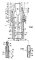
- - la figure 1 est une vue en coupe du corps de buse avec une busette de chauffe et un injecteur de coupe en position non montée ;
- - la figure 2 est une demi-vue partielle analogue à la figure 1, avec décalage angulaire ;
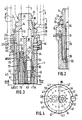
- - la figure 3 est une vue analogue à la figure 1, avec la busette de chauffe et l'injecteur de coupe en position montée ;
- - la figure 4 est une vue frontale selon les flèches III-III de la buse selon la figure 3 ;
- - la figure 5 est une vue en coupe du corps de buse selon la figure 1, équipé de deux injecteurs de coupe ;
- - la figure 6 est une vue frontale selon la direction VI-VI de la figure 5 ;
- - la figure 7 est une vue en coupe transversale selon la ligne VII-VII de la figure 5.
- - les figures 8 et 9 sont des vues de détails à échelle agrandie des figures 5 et 3 respectivement.
- - Figure 1 is a sectional view of the nozzle body with a heating nozzle and a cutting injector in the unassembled position;
- - Figure 2 is a partial half-view similar to Figure 1, with angular offset;
- - Figure 3 is a view similar to Figure 1, with the heating nozzle and the cutting injector in the mounted position;
- - Figure 4 is a front view along arrows III-III of the nozzle according to Figure 3;
- - Figure 5 is a sectional view of the nozzle body according to Figure 1, equipped with two cutting injectors;
- - Figure 6 is a front view in the direction VI-VI of Figure 5;
- - Figure 7 is a cross-sectional view along line VII-VII of Figure 5.
- - Figures 8 and 9 are detail views on an enlarged scale of Figures 5 and 3 respectively.
En se référant aux dessins annexés, une buse de coupe 1 est montée sur un corps de chalumeau 2 (représenté en trait interrompu) et incorporant un conduit axial d'alimentation en oxygène de coupe 3, un conduit d'alimentation en oxygène de chauffe 4 se subdivisant en deux conduits 4′ et 4˝, et un conduit d'alimentation en combustible 5.Referring to the accompanying drawings, a
La buse de coupe comporte un corps central appelé corps dit d'injecteurs 11, sur lequel se fixe un corps dit de chauffe 12.The cutting nozzle comprises a central body called a body called injectors 11, on which a so-called
Le corps d'injecteurs 11 comporte une partie amont 13 de forme générale tronconique adaptée à s'engager dans le corps de chalumeau 2 et présentant trois gorges axialement étagées 14, 15, 16, dont l'une 14, vient en regard du débouché de conduit d'alimentation en combustible 5, formant ainsi une chambre de distribution annulaire 14 de combustible, et dont les deux autres 15 et 16 viennent en regard des débouchés respectivement des conduits 4′ et 4˝ d'alimentation en oxygène de chauffe formant ainsi deux chambres de distribution annulaires d'oxygène de chauffe 15 et 16 disposées axialement de part et d'autre de la chambre de combustible 14. Un large conduit axial 18 se présente en regard du débouché du conduit d'oxygène de coupe 3, tandis qu'on distingue, de la périphérie vers l'intérieur ;
- A la périphérie une pluralité annulaire (huit au dessin) de conduits longitudinaux 21, dits de propreté, partant de la chambre transversale d'alimentation en oxygène de chauffe 16 et débouchant tous au travers d'un épaulement 22 de bloc d'injecteurs 11 ;
- deux conduits longitudinaux dits de préchauffe 23 et 24 alimentés en combustible via un conduit 25 partant de la chambre de combustible 14 et via un petit conduit à injecteur 26 partant de la chambre annulaire en oxygène de chauffe 16 et débouchant tous au travers d'un épaulement 22 du bloc d'injecteurs 11 (cf. figures 1,3, 5 et 8) ;
- une pluralité annulaire (seize au dessin) de conduits dits de chauffe 28 inclinés vers l'extérieur et vers l'aval, alimentés en oxygène par un conduit à injecteur 29 partant de la chambre annulaire d'oxygène de chauffe 15 et par un conduit 30 partant de la chambre annulaire de combustible 14 et débouchant tous au travers de l'épaulement 22 du corps d'injecteurs 11 ;
- intercalées entre certains conduits de la couronne de conduits de chauffe 28 sont agencés (cf. figure 2) une pluralité annulaire de conduits de chauffe carburante 31 raccordés via un conduit 32 à la chambre d'alimentation en combustible 14 et via un conduit 33 à injecteur 34 partant de la chambre d'alimentation en oxygène de chauffe 16. Ces conduits de chauffe carburante 31 sont longitudinaux et, contrairement aux conduits de chauffe 28, qui, inclinés vers l'extérieur, débouchent au travers de l'épaulement amont 22, se prolongent dans une partie aval en forme de noyau 35 du corps d'injecteurs 11 jusqu'à déboucher au travers d'une face frontale terminale 36 de ce corps d'injecteurs 11 ;
- le conduit d'oxygène de coupe 18 se subdivise en deux conduits 37 et 38, dont les axes sont dans un plan diamétral moyen entre les conduits de préchauffe 23 et 24 et débouchant au travers de la face frontale 36.The injector body 11 comprises an
- At the periphery an annular plurality (eight in the drawing) of
- two longitudinal conduits known as preheating 23 and 24 supplied with fuel via a
- An annular plurality (sixteen in the drawing) of so-called
- interposed between certain conduits of the ring of
the
Le corps de chauffe 12 se présente sous forme d'une pièce annulaire avec, côté amont, une face interne 41 montée à coulissement sur la face externe 42 du noyau 35 du corps d'injecteurs 11 jusqu'à venir en butée contre l'épaulement 22 de ce corps d'injecteurs 11, avec une orientation prédéterminée grâce à des goupilles 43 par rapport au corps d'injecteurs 11, et grâce à une clavette 44 par rapport au corps de chalumeau 2. Du côté aval, le corps de chauffe 12 se referme en une pièce massive 61 au delà d'un pan annulaire coupé 62 dont le diamètre le plus évasé se situe à distance faible de la face frontale 36 du bloc d'injecteurs 11, de façon à former une gorge transversale circulaire 55 dans laquelle débouchent les conduits de chauffe carburante 31.The
Ce corpos de chauffe 12 présente une collerette radialement vers l'extérieur 45 dans laquelle sont ménagés des conduits longitudinaux 46 en prolongement exact des conduits de propreté 21 du corps d'injecteurs 11 et débouchant en 47. De même, deux conduits longitidunaux de préchauffe 48 et 49 se présentent en prolongement exact des deux conduits de préchauffe 23 et 24 du corps d'injecteurs 11 pour déboucher en 50 et 51 au travers de la face transversale frontale 52 du corps de chauffe 12. Egalement des conduits de chauffe 53 inclinés vers l'aval et vers le centre, prennent naissance en amont en regard exact - non visible aux dessins - du débouché des conduits de chauffe 28 du corps d'injecteurs 11, pour déboucher en 54 au traverse de la face frontale 52 du corps de chauffe 12. Le corps de chauffe 12 présente également deux larges perforations longitudinales 56 et 57 se présentant axialement dans le prolongement des conduits d'oxygène de coupe 37 et 38.This
Ces perforations 56 et 57 ainsi qu'une partie terminale évasée 58 et 59 des conduits 37 et 38 servent de logements à un insert de coupe 63, à un second insert de coupe 64 ou à un insert formant busette de chauffe 65.These
L'insert de coupe 63, ou 64, présente un large conduit 66 à tuyère convergente-divergent 67. Il présente sur sa face externe un filetage 68 adapté à coopérer avec un taraudage 59 du logement en 58 et 59 et une pluralité annulaire de fraisures longitudinales 69. Dans la position montée, (figures 3 et 5), un insert de coupe 63 (figure 3) ou 63-64 (figure 5) est vissé à fond dans un logement (57-59) et/ou (56-58), le conduit axial 66 étant alimenté en oxygène de coupe par le conduit 38 (figure 3) par les conduits 38 et 37 (figure 5), tandis que les fraisures 69 forment avec la paroi des logements 56 ou 57 une couronne annulaire de conduits 69 autour du conduit axial 66, raccordés en amont à la chambre de mélange de combustible formée par la gorge circulaire 55 elle-même alimentée par les conduits 31.The cutting insert 63, or 64, has a
Une busette de chauffe 65 présente une tête 70 à joint d'étanchéité 71 avec un conduit axial 72 débouchant radialement par des conduits 73 dans une gorge 74 formant, en position montée, une chambre distributrice 74 d'oxygène (dit de coupe qui est ici utilisée en oxygène de chauffe pour une couronne de conduits longitudinaux 75, de diamètre de plus en plus grand jusqu'à déboucher en 76. La busette de chauffe 65 présente un rétrécissement annulaire 77 à l'endroit de la gorge transversale 55 et à ce niveau sont ménagés des perforations radiales 78, de sorte qu'une partie aval 75′ des conduits 75 est alimentée en mélange combustible.A
On remarque qu'entre les logements 56 et 57 du corps annulaire de chauffe 12 est pratiquée une saignée 80 qui forme un conduit de chauffe supplémentaire à effet carburant notamment utile lorsque la buse est équipée de deux inserts formant deux jets de coupe intervenant successivement, la chauffe intermédiaire ainsi réalisée assurant une reprise de chauffe dans une zone moyenne ou de fond de la saignée ébauchée par le premier jet de coupe 64.It is noted that between the
On note que dans les deux cas, la chauffe avant coupe est renforcée en 50 et 51 qui représente le front d'attaque de la future coupe.We note that in both cases, the pre-cut heating is reinforced at 50 and 51 which represents the leading edge of the future cut.
D'autre part, on note que le jet de coupe 63 qui intervient soit à titre unique après la busette de chauffe (figure 3) soit après l'ébauche de saignée pratiquée par le jet de coupe 64 (figure 5) voit son action renforcée par une couronne annulaire de flammes 69 alimentées en mélange également à effet carburant.On the other hand, it is noted that the
La couronne annulaire de jets d'oxygène débouchant à la sortie 47 des conduits 46 au niveau de l'écrou de fixation de la buse, a pour rôle d'empêcher toute liaison définitive entre buse et écrou qui habituellement peut résulter de projections de métal en fusion. L'oxygène délivré à cet endroit assure un brûlage instantané, ou au moins une action de repoussement, des projections de métal en fusion.The annular ring of oxygen jets opening at the
Claims (14)
Applications Claiming Priority (2)
| Application Number | Priority Date | Filing Date | Title |
|---|---|---|---|
| FR8900199 | 1989-01-10 | ||
| FR8900199A FR2641849B1 (en) | 1989-01-10 | 1989-01-10 | STEEL CUTTING NOZZLE |
Publications (2)
| Publication Number | Publication Date |
|---|---|
| EP0378461A1 true EP0378461A1 (en) | 1990-07-18 |
| EP0378461B1 EP0378461B1 (en) | 1993-06-09 |
Family
ID=9377565
Family Applications (1)
| Application Number | Title | Priority Date | Filing Date |
|---|---|---|---|
| EP90400045A Expired - Lifetime EP0378461B1 (en) | 1989-01-10 | 1990-01-08 | Cutting nozzle for iron and steel processing |
Country Status (9)
| Country | Link |
|---|---|
| US (1) | US5002261A (en) |
| EP (1) | EP0378461B1 (en) |
| JP (1) | JPH02247080A (en) |
| AT (1) | ATE90438T1 (en) |
| DE (1) | DE69001818T2 (en) |
| DK (1) | DK0378461T3 (en) |
| ES (1) | ES2041147T3 (en) |
| FR (1) | FR2641849B1 (en) |
| PT (1) | PT92826B (en) |
Families Citing this family (2)
| Publication number | Priority date | Publication date | Assignee | Title |
|---|---|---|---|---|
| DE10144179C1 (en) * | 2001-09-07 | 2003-04-17 | Messer Cutting & Welding Gmbh | Cutting torch with multifunctional torch head |
| DE102013106511B4 (en) | 2013-03-27 | 2015-09-24 | Gefam Gmbh | Nozzle for cutting steel workpieces |
Citations (2)
| Publication number | Priority date | Publication date | Assignee | Title |
|---|---|---|---|---|
| US2302734A (en) * | 1937-02-11 | 1942-11-24 | Linde Air Prod Co | Blowpipe nozzle |
| FR2613264A1 (en) * | 1987-04-01 | 1988-10-07 | Air Liquide | OXYCUTTING METHOD AND NOZZLE |
Family Cites Families (1)
| Publication number | Priority date | Publication date | Assignee | Title |
|---|---|---|---|---|
| US4455176A (en) * | 1983-05-17 | 1984-06-19 | Union Carbide Corporation | Post-mixed oxy-fuel gas cutting torch and nozzle and method of oxy-fuel gas cutting |
-
1989
- 1989-01-10 FR FR8900199A patent/FR2641849B1/en not_active Expired - Fee Related
-
1990
- 1990-01-08 EP EP90400045A patent/EP0378461B1/en not_active Expired - Lifetime
- 1990-01-08 US US07/462,069 patent/US5002261A/en not_active Expired - Fee Related
- 1990-01-08 ES ES199090400045T patent/ES2041147T3/en not_active Expired - Lifetime
- 1990-01-08 DE DE9090400045T patent/DE69001818T2/en not_active Expired - Fee Related
- 1990-01-08 DK DK90400045.2T patent/DK0378461T3/en active
- 1990-01-08 AT AT90400045T patent/ATE90438T1/en not_active IP Right Cessation
- 1990-01-10 JP JP2001641A patent/JPH02247080A/en active Pending
- 1990-01-10 PT PT92826A patent/PT92826B/en not_active IP Right Cessation
Patent Citations (2)
| Publication number | Priority date | Publication date | Assignee | Title |
|---|---|---|---|---|
| US2302734A (en) * | 1937-02-11 | 1942-11-24 | Linde Air Prod Co | Blowpipe nozzle |
| FR2613264A1 (en) * | 1987-04-01 | 1988-10-07 | Air Liquide | OXYCUTTING METHOD AND NOZZLE |
Also Published As
| Publication number | Publication date |
|---|---|
| ES2041147T3 (en) | 1993-11-01 |
| US5002261A (en) | 1991-03-26 |
| FR2641849B1 (en) | 1991-03-22 |
| ATE90438T1 (en) | 1993-06-15 |
| PT92826B (en) | 1995-12-29 |
| DK0378461T3 (en) | 1993-10-25 |
| PT92826A (en) | 1991-09-13 |
| DE69001818D1 (en) | 1993-07-15 |
| DE69001818T2 (en) | 1993-09-23 |
| EP0378461B1 (en) | 1993-06-09 |
| JPH02247080A (en) | 1990-10-02 |
| FR2641849A1 (en) | 1990-07-20 |
Similar Documents
| Publication | Publication Date | Title |
|---|---|---|
| EP0255430B1 (en) | Cutting nozzle with two rings of heating gas passages for iron and steel industry | |
| CA2144349C (en) | Process and device for spraying a liquid, particularly a high-viscosity liquid, comprising the injection of at least one auxiliary gas | |
| EP1770333B1 (en) | Anti-coking injector arm | |
| FR2817017A1 (en) | Turbine engine combustion chamber fuel injector cooling system has third coaxial tube round fuel feed tubes to deliver coolant | |
| EP1806536A1 (en) | Cooling of a multimode injection device for a combustion chamber, particularly for a gas turbine | |
| FR2494777A1 (en) | FUEL INJECTION NOZZLE TUBING FOR TURBOJET ENGINE | |
| EP0933981A1 (en) | Nozzle/nozzle holder arrangement for a plasma torch | |
| EP1489359B1 (en) | Annular combustion chamber for turbomachine | |
| FR2918726A1 (en) | Cylindrical low-pressure turbine and compressor shafts connector for aeronautical turbomachine, has shafts with sets of teeth, where each tooth of one set has constant thickness, and teeth flanks forming clearance before applying torque | |
| FR2460312A1 (en) | DEVICE FOR PRODUCING CARBON BLACK | |
| EP2683930A1 (en) | Injector for mixing two propellants comprising at least one injection element with a tricoaxial structure | |
| EP0378461B1 (en) | Cutting nozzle for iron and steel processing | |
| EP0397561B1 (en) | Cutting head with oxygen jet | |
| EP0287420B2 (en) | Process and nozzle for oxy-cutting | |
| FR2644558A1 (en) | Arc furnace equipped with fuel oil/oxygen burners and fuel oil/oxygen burner | |
| EP0095951B1 (en) | Piston shaft and piston, especially for internal-combustion engines equipped with such a shaft | |
| EP0683886B1 (en) | Snow gun | |
| EP0676024B1 (en) | Gas torch nozzle | |
| FR2987428A1 (en) | Arrangement for combustion chamber of e.g. turbopropeller of aircraft, has ring system including interior track having complementary form to that of outer surface, where track cooperates with outer surface to form connection kneecap | |
| EP0605278B1 (en) | Nozzle and cutting torch | |
| EP0983472A1 (en) | Oxyacetylene cutting apparatus | |
| FR2970551A1 (en) | Terminal portion for fuel injector of annular combustion chamber of e.g. turbojet of aircraft, has outer pipe for supplying fuel at end, and nose injector mounted on end of outer pipe by threaded ends that are screwed with each other | |
| FR2762050A1 (en) | IC engine fuel distributor | |
| EP0963517A1 (en) | Device dispensing fuel for supplying an internal combustion engine cylinder | |
| FR2672524A1 (en) | LINGOTIERE FOR CONTINUOUS CASTING OF METAL PRODUCTS. |
Legal Events
| Date | Code | Title | Description |
|---|---|---|---|
| PUAI | Public reference made under article 153(3) epc to a published international application that has entered the european phase |
Free format text: ORIGINAL CODE: 0009012 |
|
| 17P | Request for examination filed |
Effective date: 19900111 |
|
| AK | Designated contracting states |
Kind code of ref document: A1 Designated state(s): AT BE CH DE DK ES FR GB GR IT LI LU NL SE |
|
| 17Q | First examination report despatched |
Effective date: 19910903 |
|
| GRAA | (expected) grant |
Free format text: ORIGINAL CODE: 0009210 |
|
| AK | Designated contracting states |
Kind code of ref document: B1 Designated state(s): AT BE CH DE DK ES FR GB GR IT LI LU NL SE |
|
| PG25 | Lapsed in a contracting state [announced via postgrant information from national office to epo] |
Ref country code: SE Effective date: 19930609 Ref country code: GR Free format text: LAPSE BECAUSE OF FAILURE TO SUBMIT A TRANSLATION OF THE DESCRIPTION OR TO PAY THE FEE WITHIN THE PRESCRIBED TIME-LIMIT Effective date: 19930609 Ref country code: GB Effective date: 19930609 Ref country code: AT Effective date: 19930609 |
|
| REF | Corresponds to: |
Ref document number: 90438 Country of ref document: AT Date of ref document: 19930615 Kind code of ref document: T |
|
| ITF | It: translation for a ep patent filed |
Owner name: ING. A. GIAMBROCONO & C. S.R.L. |
|
| REF | Corresponds to: |
Ref document number: 69001818 Country of ref document: DE Date of ref document: 19930715 |
|
| REG | Reference to a national code |
Ref country code: DK Ref legal event code: T3 |
|
| REG | Reference to a national code |
Ref country code: ES Ref legal event code: FG2A Ref document number: 2041147 Country of ref document: ES Kind code of ref document: T3 |
|
| GBV | Gb: ep patent (uk) treated as always having been void in accordance with gb section 77(7)/1977 [no translation filed] |
Effective date: 19930609 |
|
| EPTA | Lu: last paid annual fee | ||
| PG25 | Lapsed in a contracting state [announced via postgrant information from national office to epo] |
Ref country code: LI Effective date: 19940131 Ref country code: CH Effective date: 19940131 |
|
| PLBE | No opposition filed within time limit |
Free format text: ORIGINAL CODE: 0009261 |
|
| STAA | Information on the status of an ep patent application or granted ep patent |
Free format text: STATUS: NO OPPOSITION FILED WITHIN TIME LIMIT |
|
| 26N | No opposition filed | ||
| REG | Reference to a national code |
Ref country code: CH Ref legal event code: PL |
|
| PGFP | Annual fee paid to national office [announced via postgrant information from national office to epo] |
Ref country code: DE Payment date: 19971222 Year of fee payment: 9 |
|
| PGFP | Annual fee paid to national office [announced via postgrant information from national office to epo] |
Ref country code: DK Payment date: 19971229 Year of fee payment: 9 |
|
| PGFP | Annual fee paid to national office [announced via postgrant information from national office to epo] |
Ref country code: NL Payment date: 19971231 Year of fee payment: 9 |
|
| PGFP | Annual fee paid to national office [announced via postgrant information from national office to epo] |
Ref country code: BE Payment date: 19980108 Year of fee payment: 9 |
|
| PGFP | Annual fee paid to national office [announced via postgrant information from national office to epo] |
Ref country code: ES Payment date: 19980113 Year of fee payment: 9 |
|
| PGFP | Annual fee paid to national office [announced via postgrant information from national office to epo] |
Ref country code: LU Payment date: 19980210 Year of fee payment: 9 |
|
| PG25 | Lapsed in a contracting state [announced via postgrant information from national office to epo] |
Ref country code: LU Free format text: LAPSE BECAUSE OF NON-PAYMENT OF DUE FEES Effective date: 19990108 |
|
| PG25 | Lapsed in a contracting state [announced via postgrant information from national office to epo] |
Ref country code: ES Free format text: LAPSE BECAUSE OF NON-PAYMENT OF DUE FEES Effective date: 19990109 |
|
| PG25 | Lapsed in a contracting state [announced via postgrant information from national office to epo] |
Ref country code: BE Free format text: LAPSE BECAUSE OF NON-PAYMENT OF DUE FEES Effective date: 19990131 |
|
| PG25 | Lapsed in a contracting state [announced via postgrant information from national office to epo] |
Ref country code: DK Free format text: LAPSE BECAUSE OF NON-PAYMENT OF DUE FEES Effective date: 19990202 |
|
| BERE | Be: lapsed |
Owner name: S.A. L' AIR LIQUIDE POUR L'ETUDE ET L'EXPLOITATION Effective date: 19990131 |
|
| PG25 | Lapsed in a contracting state [announced via postgrant information from national office to epo] |
Ref country code: NL Free format text: LAPSE BECAUSE OF NON-PAYMENT OF DUE FEES Effective date: 19990801 |
|
| PG25 | Lapsed in a contracting state [announced via postgrant information from national office to epo] |
Ref country code: DE Free format text: LAPSE BECAUSE OF NON-PAYMENT OF DUE FEES Effective date: 19991103 |
|
| PGFP | Annual fee paid to national office [announced via postgrant information from national office to epo] |
Ref country code: FR Payment date: 19991213 Year of fee payment: 11 |
|
| REG | Reference to a national code |
Ref country code: DK Ref legal event code: EBP |
|
| PG25 | Lapsed in a contracting state [announced via postgrant information from national office to epo] |
Ref country code: FR Free format text: LAPSE BECAUSE OF NON-PAYMENT OF DUE FEES Effective date: 20010928 |
|
| REG | Reference to a national code |
Ref country code: ES Ref legal event code: FD2A Effective date: 20010503 |
|
| REG | Reference to a national code |
Ref country code: FR Ref legal event code: ST |
|
| PG25 | Lapsed in a contracting state [announced via postgrant information from national office to epo] |
Ref country code: IT Free format text: LAPSE BECAUSE OF NON-PAYMENT OF DUE FEES;WARNING: LAPSES OF ITALIAN PATENTS WITH EFFECTIVE DATE BEFORE 2007 MAY HAVE OCCURRED AT ANY TIME BEFORE 2007. THE CORRECT EFFECTIVE DATE MAY BE DIFFERENT FROM THE ONE RECORDED. Effective date: 20050108 |