EP0377862B1 - Pneumatic suction conveyor to convey pourable materials - Google Patents
Pneumatic suction conveyor to convey pourable materials Download PDFInfo
- Publication number
- EP0377862B1 EP0377862B1 EP89123319A EP89123319A EP0377862B1 EP 0377862 B1 EP0377862 B1 EP 0377862B1 EP 89123319 A EP89123319 A EP 89123319A EP 89123319 A EP89123319 A EP 89123319A EP 0377862 B1 EP0377862 B1 EP 0377862B1
- Authority
- EP
- European Patent Office
- Prior art keywords
- line
- delivery
- closure member
- lines
- vent valve
- Prior art date
- Legal status (The legal status is an assumption and is not a legal conclusion. Google has not performed a legal analysis and makes no representation as to the accuracy of the status listed.)
- Expired - Lifetime
Links
Images
Classifications
-
- B—PERFORMING OPERATIONS; TRANSPORTING
- B65—CONVEYING; PACKING; STORING; HANDLING THIN OR FILAMENTARY MATERIAL
- B65G—TRANSPORT OR STORAGE DEVICES, e.g. CONVEYORS FOR LOADING OR TIPPING, SHOP CONVEYOR SYSTEMS OR PNEUMATIC TUBE CONVEYORS
- B65G53/00—Conveying materials in bulk through troughs, pipes or tubes by floating the materials or by flow of gas, liquid or foam
- B65G53/34—Details
- B65G53/52—Adaptations of pipes or tubes
- B65G53/56—Switches
-
- B—PERFORMING OPERATIONS; TRANSPORTING
- B65—CONVEYING; PACKING; STORING; HANDLING THIN OR FILAMENTARY MATERIAL
- B65G—TRANSPORT OR STORAGE DEVICES, e.g. CONVEYORS FOR LOADING OR TIPPING, SHOP CONVEYOR SYSTEMS OR PNEUMATIC TUBE CONVEYORS
- B65G53/00—Conveying materials in bulk through troughs, pipes or tubes by floating the materials or by flow of gas, liquid or foam
- B65G53/04—Conveying materials in bulk pneumatically through pipes or tubes; Air slides
- B65G53/24—Gas suction systems
Definitions
- the invention relates to a ventilation valve for a pneumatic suction conveyor system for conveying free-flowing materials in a conveyor line between a task and a delivery point, which is arranged in the conveyor line and has a closure member which is opened to relieve the vacuum and empty the downstream part of the conveyor line.
- the invention further relates to a suction conveyor system with such a ventilation valve.
- ventilation valves In suction conveyor systems for free-flowing materials, ventilation valves generally have to be provided in the conveyor lines, for example at the end of a conveyor cycle partially or completely empty the delivery line (DE-A-23 61 279). This can be necessary, for example, if long conveying distances have to be overcome and it is to be avoided that the material still in the line settles when the conveying flow is shut off, the suction fan or the like is shut down. This material makes it difficult to restart the suction conveyor system and can even lead to blockages. Furthermore, complete or partial empty suction is necessary if, for example, different materials are transported from different feed points through a single delivery line to one or more delivery points in order to avoid mixing of the materials in the delivery line or at the delivery point. The problem arises particularly when different materials from their own storage containers are optionally fed to different delivery points via a corresponding number of delivery lines and mixing is also to be avoided (DE-A-24 36 595).
- a ventilation valve is provided at a suitable point in the delivery line.
- a T-piece is inserted into the delivery line, in whose T-web the valve is installed (DE-A-23 61 279).
- the flow is interrupted by the negative pressure breaking upstream of the ventilation valve and the suction fan sucking in the air via the ventilation valve.
- the feed line is sucked empty downstream of the ventilation valve, while the material remains upstream.
- suction nozzles or so-called proboscis are known for receiving bulk goods at a bulk goods store (DE-B-1 117 042), which consist of two concentric pipes, of which the inner pipe is part of a delivery line and is connected to a suction fan and the outer one Supply air duct forms, the end of which is the Somewhat overlooked at the end of the delivery line.
- the deflection of the air from the outer tube to the inner tube creates an injector effect which disrupts the bulk material.
- the inflow cross section of the supply air line can be controlled to adjust the flow rate.
- a concentric orifice is provided in the supply air line, which closes ring-shaped recesses on the supply air line during conveying operation. The recesses are opened by axially moving the orifice so that the negative pressure in the supply air line and on the suction nozzle breaks down. So here the interruption does not take place within the flow, but by controlling the supply air at the suction point.
- the invention is based on the object of designing a ventilation valve for a suction conveyor system of the construction described at the outset in such a way that an abrupt and at the same time complete interruption of the flow in the region of the ventilation valve is possible. It should be possible, especially in suction conveyor systems with several feed points and / or several discharge points, to quickly and effectively empty individual feed lines.
- the delivery line is interrupted transversely to the line axis over its entire circumference to form a loyalty point to form the ventilation valve and that the closure member on the delivery line is axially displaceable and is guided by this and closes the separation point in the closed position and releases an annular gap open to the environment in the open position.
- the invention does not use a conventional valve in which a closure member closes against a valve seat, but the delivery line is interrupted over its entire circumference.
- a closure member which is axially displaceable on the line, an annular gap can be exposed at the point of interruption through which the ambient air is sucked in. The air flows over the entire outer circumference into the delivery line and leads to an immediate stopping of the flow at the point of interruption.
- Practical tests have also shown that a sudden piece of the upstream line section is still sucked empty due to the sudden air ingress over the entire circumference, so that no material remains in the area of the ventilation valve. Nor can individual particles be sucked in from this line section over a longer period of time. In this way, it is possible to interrupt the delivery flow in the shortest possible time and in an effective manner and to empty the downstream line section. If the closure member is axially displaced so that the annular gap is closed, uninterrupted delivery is possible again.
- a preferred embodiment is characterized in that the closure member at least one of the upstream and downstream sections of the conveyor line is guided.
- the closure member is guided with one end on one section of the conveying line and bluntly connects with the other end in the closed position to the other section.
- the line sections located upstream and downstream of the separation point thus end with a gap of a certain width which is bridged by the closure member guided on one of the line sections, the closure member being butt-connected in the closed position to the respectively opposite line section.
- closure member is designed as a ring slide and bridges the annular gap on the upstream and downstream sections of the conveyor line.
- closure member has on its outside a cylindrical collar which is guided in a pressure medium cylinder surrounding the closure member and - acting as a piston - can be acted upon with pressure medium on both sides.
- the aforementioned design of the closure member has the advantage that it also has part of the drive necessary for its movement, namely the piston of a pressure medium cylinder surrounding the closure member. This results in a simple and extremely space-saving training. Furthermore, the concentrically acting closing and opening force ensures perfect functioning, in particular it prevents the tilting forces acting on the displaceable closure member, which could impair the guidance of the closure member and its function.
- the collar forming the piston of the pressure medium cylinder can be designed as a free-flying piston, the movement of which is limited by the end closures of the cylinder.
- This training is recommended if the closure member is designed as a ring slide.
- the closure member with its upstream and downstream ends of the collar engages through the cylinder at its front ends.
- This training is particularly recommended when the closure member bluntly connects to a line section in the closed position.
- This embodiment also has the advantage that the delivery line only has to be sealed against the ambient pressure, but not against the increased working pressure of the pressure medium cylinder.
- the invention further relates to a pneumatic suction conveyor system for selectively conveying free-flowing materials from at least one feed point to at least one discharge point with a distributor located between the two, the input of which via a feed line to one of the feed points and the output of each via a feed line is connected to one of the delivery points and has a distribution line arranged between the input and the output, which optionally connects one of the delivery lines to one of the supply lines.
- the material can be transported from one delivery point to several delivery points, from several delivery points to one delivery point or from several delivery points to several delivery points.
- a distributor is arranged between these two points.
- This can be, for example, a type of pipe switch which can be moved linearly along the ends of the delivery lines and / or the supply lines.
- it can also be a so-called rotary tube distributor, in which the delivery lines and / or the supply lines are arranged on a circle and the distributor line can be rotated about an axis of rotation enclosing the center of the circle.
- a ventilation valve designed according to the invention is arranged at the inlet of the distributor line.
- the distributor is designed in the form of a rotary tube distributor, at the input of which the delivery lines end concentrically around an axis in a radial plane and the inlet end of the delivery line is rotatable in this radial plane on the arrangement circle of the delivery lines and is supported at the other end in the axis of rotation, so
- the distributor line is arranged with its input end at an axial distance from the radial plane to form the annular gap, the closure member is guided on this end and is displaceable up to the butt connection to one of the delivery lines.
- the distributor line is attached with its input-side end to a support mounted in the axis of rotation, which at the same time receives the pressure medium cylinder for the closure member.
- This version takes into account the limited space in a rotary distributor in an optimal way.
- the pressure medium lines for the pressure medium cylinder lead into a bearing part of the rotary bearing connected to the opposite end of the distributor line and are connected via an annular channel to pressure medium supply lines which end at a fixed bearing part of the rotary bearing.
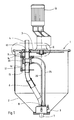
- the rotary tube distributor according to Fig. 1 is between a plurality of material feed points, not shown, e.g. arranged in the form of storage containers containing the material, and one or more delivery points. If there are several delivery points, the representation according to FIG. 1 is followed by a component of the same design, as mirrored to the horizontal, as shown in FIG. 1.
- the rotary tube distributor 1 has a housing 2 with a front end 3.
- the delivery lines 4 end at the front end 3.
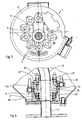
- a large number of such delivery lines 4 open on a circle 5 at the front end 3 of the rotary tube distributor.
- a distributor line 6 is arranged within the housing 2 and optionally connects one of the delivery lines 4 to an outgoing line 7.
- the outlet line 7 can be the supply line to a delivery point or the bridge to a rotating tube distributor arranged in mirror image, the distribution line connecting a number of supply lines corresponding to the delivery points, each with a delivery line 4.
- the distributor line 6 is mounted with its end 8 facing the supply line 7 in a pivot bearing 9, the axis of which coincides with the center of the arrangement circle 5 of the delivery lines 4.
- the other end of the distribution line 6 is seated on a carrier 9 which can be rotated about the same axis of rotation by means of a drive motor 10, so that this end can be moved onto the arrangement circle 5 of the delivery lines 4.
- the ventilation valve designated overall by 11, is arranged.
- the end 12 of the distributor line 6 is arranged at a distance from the end 13 of the delivery line 4.
- the resulting free space at the separation point is bridged by a closure member 14.
- the distributor line 6 is connected to the carrier 9 in the region of its end 12 via a flange 15 and a support rod 16.
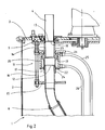
- FIG. 11 The structure of the ventilation valve 11 can be seen in more detail in FIG.
- its closure member 14 is tubular and is guided with its one end 17 on the end of the distribution line 6, while its other end 18 in the closed position is butt-connected to the end 13 of the delivery line 4.
- the closure member 14 - in the drawing downwards - is axially displaced, so that an open annular gap is formed between the end 13 of the delivery line 4 and the end face 18, through which the ambient air is sucked in and the delivery in the delivery line 4 is interrupted.
- the closure member 14 has a collar 19 on the outside, which is arranged within a pressure medium cylinder 20, the front ends 21, 22 of which are penetrated by a tubular part 23, 24 of the closure member.
- Pressure medium for example compressed air, can be fed into the pressure medium cylinder 20 from both ends via connecting lines 25, 26, so that the collar 19 of the closure member 14 is double-acting Piston forms which moves the closure member between the closed and open positions.
- the pressure medium lines 25, 26 are guided downward into the rotary bearing 9 within the rotary tube distributor. They open there in the rotating part 27, which is mounted in the non-rotatable part 29 via ball bearings 28.
- annular grooves 30, 31 are provided at an axial distance from one another, with which the pressure medium lines 25, 26 are connected via bores.
- the supply lines 32, 33 are connected to the ring grooves 30, 31.
Description
Die Erfindung betrifft ein Belüftungsventil für eine pneumatische Saugförderanlage zum Fördern rieselfähiger Materialien in einer Förderleitung zwischen einer Aufgabeund einer Abgabestelle, das in der Förderleitung angeordnet ist und ein Verschlußorgan aufweist, das zum Abbau des Unterdrucks und Leersaugen des stromabwärts liegenden Teils der Förderleitung geöffnet wird. Ferner betrifft die Erfindung eine saugförderanlage mit einem solchen Belüftungsventil.The invention relates to a ventilation valve for a pneumatic suction conveyor system for conveying free-flowing materials in a conveyor line between a task and a delivery point, which is arranged in the conveyor line and has a closure member which is opened to relieve the vacuum and empty the downstream part of the conveyor line. The invention further relates to a suction conveyor system with such a ventilation valve.
In Saugförderanlagen für rieselfähige Materialien müssen in den Förderleitungen in der Regel Belüftungsventile vorgesehen werden, um beispielsweise am Ende eines Förderzyklus die Förderleitung ganz oder teilweise leerzusaugen (DE-A-23 61 279). Dies kann beispielsweise dann notwendig sein, wenn lange Förderstrecken zu überwinden sind und vermieden werden soll, daß beim Absperren des Förderstroms, stillsetzen des Sauggebläses oder dergleichen, das noch in der Leitung befindliche Material sich absetzt. Dieses Material erschwert die neuerliche Inbetriebnahme der saugförderanlage und kann sogar zu Verstopfungen führen. Ferner ist das vollständige oder teilweise Leersaugen dann notwendig, wenn beispielsweise verschiedene Materialien von verschiedenen Aufgabestellen durch eine einzige Förderleitung an eine oder mehrere Abgabestellen transportiert werden, um in der Förderleitung oder an der Abgabestelle ein vermischen der Materialien zu vermeiden. Ganz besonders stellt sich das Problem dann, wenn verschiedene Materialien aus jeweils eigenen Vorratsbehältern über eine entsprechende Anzahl von Förderleitungen wahlweise verschiedenen Abgabestellen zugeführt und dabei gleichfalls vermischen vermieden werden sollen (DE-A-24 36 595).In suction conveyor systems for free-flowing materials, ventilation valves generally have to be provided in the conveyor lines, for example at the end of a conveyor cycle partially or completely empty the delivery line (DE-A-23 61 279). This can be necessary, for example, if long conveying distances have to be overcome and it is to be avoided that the material still in the line settles when the conveying flow is shut off, the suction fan or the like is shut down. This material makes it difficult to restart the suction conveyor system and can even lead to blockages. Furthermore, complete or partial empty suction is necessary if, for example, different materials are transported from different feed points through a single delivery line to one or more delivery points in order to avoid mixing of the materials in the delivery line or at the delivery point. The problem arises particularly when different materials from their own storage containers are optionally fed to different delivery points via a corresponding number of delivery lines and mixing is also to be avoided (DE-A-24 36 595).
Zu diesem Zweck wird an geeigneter stelle der Förderleitung ein Belüftungsventil vorgesehen. Im einfachsten Fall wird in die Förderleitung ein T-Stück eingesetzt, in dessen T-Steg das ventil eingebaut ist (DE-A-23 61 279). Durch Öffnen des Belüftungsventils wird der Förderstrom unterbrochen, indem der Unterdruck stromaufwärts des Belüftungsventils zusammenbricht und das Sauggebläse die Luft über das Belüftungsventil ansaugt. Die Förderleitung wird stromabwärts des Belüftungsventils leergesaugt, während das Material stromaufwärts liegenbleibt.For this purpose, a ventilation valve is provided at a suitable point in the delivery line. In the simplest case, a T-piece is inserted into the delivery line, in whose T-web the valve is installed (DE-A-23 61 279). By opening the ventilation valve, the flow is interrupted by the negative pressure breaking upstream of the ventilation valve and the suction fan sucking in the air via the ventilation valve. The feed line is sucked empty downstream of the ventilation valve, while the material remains upstream.
Herkömmliche Belüftungsventile haben den Nachteil, daß die Förderung nicht schlagartig unterbrochen wird, also zumindest über einen gewissen Zeitraum Partikel aus dem stromaufwärts des Belüftungsventil liegenden Abschnitt der Förderleitung nachgesaugt werden. Je nach Einbau-und Strömungsverhältnissen ist die Zeitdauer, innerhalb der noch einzelne Partikel nachgefördert werden, kürzer oder länger. Dieser Umstand führt insbesondere bei der Mehrkomponenten-Förderung zu entsprechender Verzögerung in den Förderzyklen. Bei Mehrkomponenten-Anlagen mit gravimetrischer oder volumetrischer Zuteilung der Komponenten auf verschiedene Abgabestellen ergibt sich das weitere Problem, daß die Genauigkeit der Materialzumessung leidet.Conventional ventilation valves have the disadvantage that the delivery is not interrupted suddenly, that is, particles are sucked in at least over a certain period of time from the section of the delivery line located upstream of the ventilation valve. Depending on the installation and flow conditions, the period of time within which individual particles are still added is shorter or longer. This fact leads to a corresponding delay in the funding cycles, particularly in the case of multi-component funding. In multi-component systems with gravimetric or volumetric allocation of the components to different delivery points, there is the further problem that the accuracy of the material metering suffers.
Es ist auch bereits vorgeschlagen worden, den Ansaugstutzen mit dem Belüftungsventil nicht senkrecht zur Leitungs-achse, sondern in einem spitzen Winkel zu dieser mit einer Neigung in Strömungsrichtung anzuordnen. Hierdurch werden jedoch in erster Linie nur die Strömungswiderstände an der Ansaugstelle, nicht jedoch. der Nachsaugeffekt vermindert. Im Gegenteil tritt hierbei eine Art Injektorwirkung auf, die zu einem ständigen Mitreißen von Partikeln aus dem stromaufwärts gelegenen Leitungsabschnitt führt.It has also already been proposed to arrange the intake port with the ventilation valve not perpendicular to the line axis, but at an acute angle to it with an inclination in the direction of flow. However, this primarily means only the flow resistances at the suction point, but not. the suction effect is reduced. On the contrary, a kind of injector action occurs, which leads to a constant entrainment of particles from the upstream line section.
Ferner sind zum Aufnehmen von schüttgut an einem Schüttgutlager Ansaugdüsen oder sogenannte Saugrüssel bekannt (DE-B-1 117 042), die aus zwei konzentrischen Rohren bestehen, von denen das innere Rohr Teil einer Förderleitung ist und an ein sauggebläse angeschlossen ist und das äußere eine Zuluftleitung bildet, deren Ende das Ende der Förderleitung etwas überragt. Durch die Umlenkung der Luft von dem äußeren in das innere Rohr entsteht eine das Schüttgut mißtreißende Injektorwirkung. Der Einströmquerschnitt der Zuluftleitung läßt sich zur Einstellung der Fördermenge steuern. Um die Förderung zu unterbrechen, ist in der Zuluftleitung eine konzentrische Blende vorgesehen, die bei Förderbetrieb ringförmige Aussparungen an der Zuluftleitung verschließt. Durch axiales verschieben der Blende werden die Aussparungen geöffnet, so daß der Unterdruck in der Zuluftleitung und an der Ansaugdüse zusammenbricht. Hier erfolgt also die Unterbrechung nicht innerhalb des Förderstromes, sondern durch Steuerung der Zuluft an der Ansaugstelle.Furthermore, suction nozzles or so-called proboscis are known for receiving bulk goods at a bulk goods store (DE-B-1 117 042), which consist of two concentric pipes, of which the inner pipe is part of a delivery line and is connected to a suction fan and the outer one Supply air duct forms, the end of which is the Somewhat overlooked at the end of the delivery line. The deflection of the air from the outer tube to the inner tube creates an injector effect which disrupts the bulk material. The inflow cross section of the supply air line can be controlled to adjust the flow rate. In order to interrupt the delivery, a concentric orifice is provided in the supply air line, which closes ring-shaped recesses on the supply air line during conveying operation. The recesses are opened by axially moving the orifice so that the negative pressure in the supply air line and on the suction nozzle breaks down. So here the interruption does not take place within the flow, but by controlling the supply air at the suction point.
Der Erfindung liegt die Aufgabe zugrunde, ein Belüftungsventil für eine saugförderanlage des eingangs geschilderten Aufbaus so auszubilden, daß eine schlagartige und zugleich vollständige Unterbrechung des Förderstroms im Bereich des Belüftungsventils möglich ist. Dabei soll insbesondere bei saugförderanlagen mit mehreren Aufgabestellen und/oder mehreren Abgabestellen ein schnelles und effektives Leersaugen einzelner Förderleitungen möglich sein.The invention is based on the object of designing a ventilation valve for a suction conveyor system of the construction described at the outset in such a way that an abrupt and at the same time complete interruption of the flow in the region of the ventilation valve is possible. It should be possible, especially in suction conveyor systems with several feed points and / or several discharge points, to quickly and effectively empty individual feed lines.
Diese Aufgabe wird erfindungsgemäß dadurch gelöst, daß zur Bildung des Belüftungsventils die Förderleitung quer zur Leitungsachse über ihren gesamten Umfang unter Bildung einer Treustelle unterbrochen ist und daß das Verschlußorgan auf der Förderleitung axial verschieblich und von dieser geführt ist und in der Schließlage die Trennstelle verschließt und in der Öffnungslage einen zur Umgebung offenen Ringspalt freigibt.This object is achieved in that the delivery line is interrupted transversely to the line axis over its entire circumference to form a loyalty point to form the ventilation valve and that the closure member on the delivery line is axially displaceable and is guided by this and closes the separation point in the closed position and releases an annular gap open to the environment in the open position.
Die Erfindung verwendet nicht ein herkömmliches ventil, bei dem ein verschlußorgan gegen einen Ventilsitz schließt, sondern es ist die Förderleitung über ihren gesamten Umfang unterbrochen. Mittels eines auf der Leitung axial verschieblich geführten Verschlußorgans kann an der Unterbrechungsstelle ein Ringspalt freigelegt werden, durch den die Umgebungsluft angesaugt wird. Dabei strömt die Luft über den gesamten äußeren Umfang in die Förderleitung ein und führt zu einem sofortigen Abriß der Strömung an der Unterbrechungsstelle. Praktische Versuche haben ferner gezeigt, daß durch den schlagartigen Lufteinbruch über den gesamten Umfang ein kurzes stück des stromaufwärts liegenden Leitungsabschnittes noch leergesaugt wird, so daß im Bereich des Belüftungsventils kein Material liegenbleibt. Auch kann es nicht passieren, daß einzelne Partikel aus diesem Leitungsabschnitt über einen längeren Zeitraum noch angesaugt werden. Auf diese Weise ist es möglich, in kürzester Frist und in effektiver Weise den Förderstrom zu unterbrechen und den stromabwärts liegenden Leitungsabschnitt leerzusaugen. Wird das verschlußorgan axial so verschoben, daß der Ringspalt verschlossen wird, so ist wieder eine unterbrechungsfreie Förderung möglich.The invention does not use a conventional valve in which a closure member closes against a valve seat, but the delivery line is interrupted over its entire circumference. By means of a closure member which is axially displaceable on the line, an annular gap can be exposed at the point of interruption through which the ambient air is sucked in. The air flows over the entire outer circumference into the delivery line and leads to an immediate stopping of the flow at the point of interruption. Practical tests have also shown that a sudden piece of the upstream line section is still sucked empty due to the sudden air ingress over the entire circumference, so that no material remains in the area of the ventilation valve. Nor can individual particles be sucked in from this line section over a longer period of time. In this way, it is possible to interrupt the delivery flow in the shortest possible time and in an effective manner and to empty the downstream line section. If the closure member is axially displaced so that the annular gap is closed, uninterrupted delivery is possible again.
Das erfindungsgemäße Prinzip läßt sich auf verschiedene Arten verwirklichen. Eine bevorzugte Ausführungsform zeichnet sich dadurch aus, daß das verschlußorgan auf wenigstens einem der stromaufwärts und stromabwärts des Ringspaltes liegenden Abschnitte der Förderleitung geführt ist.The principle according to the invention can be implemented in different ways. A preferred embodiment is characterized in that the closure member at least one of the upstream and downstream sections of the conveyor line is guided.
Bei einer Ausgestaltung der vorgenannten Ausführungsform ist vorgesehen, daß das verschlußorgan mit seinem einen Ende auf dem einen Abschnitt der Förderleitung geführt ist und mit seinem anderen Ende in der schließlage an den anderen Abschnitt stumpf anschließt.In one embodiment of the aforementioned embodiment it is provided that the closure member is guided with one end on one section of the conveying line and bluntly connects with the other end in the closed position to the other section.
Bei diesem Ausführungsbeispiel enden also die stromaufwärts und stromabwärts der Trennstelle liegenden Leitungsabschnitte mit einem Spalt von gewisser Breite, der von dem auf einem der Leitungsabschnitte geführten verschlußorgan überbrückt wird, wobei das verschlußorgan in der schließlage am jeweils gegenüberliegenden Leitungsabschnitt stumpf anschließt.In this exemplary embodiment, the line sections located upstream and downstream of the separation point thus end with a gap of a certain width which is bridged by the closure member guided on one of the line sections, the closure member being butt-connected in the closed position to the respectively opposite line section.
Statt dessen kann auch vorgesehen sein, daß das verschlußorgan als Ringschieber ausgebildet und den Ringspalt überbrückend auf den stromaufwärts und stromabwärts desselben liegenden Abschnitten der Förderleitung geführt ist.Instead, it can also be provided that the closure member is designed as a ring slide and bridges the annular gap on the upstream and downstream sections of the conveyor line.
Während beim ersten Ausführungsbeispiel die Abdichtung zwischen Verschlußorgan und Leitungsabschnitt stirnseitig erfolgt, geschieht dies bei der letztgenannten Ausführungsform umfangsseitig.While in the first embodiment the sealing between the closure member and the line section takes place on the end face, in the latter embodiment this is done on the circumference.
Eine weiterhin besonders vorteilhafte Ausführungsform zeichnet sich dadurch aus, daß das Verschlußorgan an seiner Außenseite einen zylindrischen Bund aufweist, der in einem das Verschlußorgan umgebenden Druckmittelzylinder geführt und - als Kolben wirkend - beidseitig mit Druckmittel beaufschlagbar ist.Another particularly advantageous embodiment is characterized in that the closure member has on its outside a cylindrical collar which is guided in a pressure medium cylinder surrounding the closure member and - acting as a piston - can be acted upon with pressure medium on both sides.
Die vorgenannte Ausbildung des Verschlußorgans hat den Vorteil, daß es zugleich einen Teil des für seine Bewegung notwendigen Antriebs aufweist, nämlich den Kolben eines das Verschlußorgan umgebenden Druckmittelzylinders bildet. Auf diese Weise ergibt sich eine einfache und äußerst platzsparende Ausbildung. Ferner wird durch die konzentrisch wirkende Schließ- und Öffnungskraft eine einwandfreie Funktion gewährleistet, insbesondere wird dadurch vermieden, daß auf das verschiebbare Verschlußorgan Kippkräfte wirken, die die Führung des Verschlußorgans und dessen Funktion beeinträchtigen könnten.The aforementioned design of the closure member has the advantage that it also has part of the drive necessary for its movement, namely the piston of a pressure medium cylinder surrounding the closure member. This results in a simple and extremely space-saving training. Furthermore, the concentrically acting closing and opening force ensures perfect functioning, in particular it prevents the tilting forces acting on the displaceable closure member, which could impair the guidance of the closure member and its function.
Der den Kolben des Druckmittelzylinders bildende Bund kann als Freiflugkolben ausgebildet sein, dessen Bewegung durch die stirnseitigen Abschlüsse des Zylinders begrenzt ist. Diese Ausbildung empfiehlt sich dann, wenn das Verschlußorgan als Ringschieber ausgebildet ist. Vorzugsweise jedoch ist vorgesehen, daß das Verschlußorgan mit seinen stromaufwärts und stromabwärts des Bundes liegenden Enden den Zylinder an seinen stirnseitigen Abschlüssen durchgreift. Diese Ausbildung empfiehlt sich vor allem dann, wenn das Verschlußorgan in der Schließlage an den einen Leitungsabschnitt stumpf anschließt. Auch hat diese Ausführungsform den Vorteil, daß die Abdichtung der Förderleitung nur gegenüber dem Umgebungsdruck, nicht aber gegenüber dem erhöhten Arbeitsdruck des Druckmittelzylinders erfolgen muß.The collar forming the piston of the pressure medium cylinder can be designed as a free-flying piston, the movement of which is limited by the end closures of the cylinder. This training is recommended if the closure member is designed as a ring slide. Preferably, however, it is provided that the closure member with its upstream and downstream ends of the collar engages through the cylinder at its front ends. This training is particularly recommended when the closure member bluntly connects to a line section in the closed position. This embodiment also has the advantage that the delivery line only has to be sealed against the ambient pressure, but not against the increased working pressure of the pressure medium cylinder.
Zur Lösung der zweiten Teilaufgabe betrifft die Erfindung ferner eine pneumatische Saugförderanlage zum wahlweisen Fördern rieselfähiger Materialien von wenigstens einer Aufgabestelle zu wenigstens einer Abgabestelle mit einem zwischen den beiden liegenden Verteiler, dessen Eingang über je eine Förderleitung mit einer der Aufgabestellen und dessen Ausgang über je eine Zuteilleitung mit einer der Abgabestellen verbunden ist und der eine zwischen dem Eingang und dem Ausgang angeordnete Verteilerleitung aufweist, die wahlweise eine der Förderleitungen mit einer der Zuteilleitungen verbindet.To solve the second subtask, the invention further relates to a pneumatic suction conveyor system for selectively conveying free-flowing materials from at least one feed point to at least one discharge point with a distributor located between the two, the input of which via a feed line to one of the feed points and the output of each via a feed line is connected to one of the delivery points and has a distribution line arranged between the input and the output, which optionally connects one of the delivery lines to one of the supply lines.
Bei Saugförderanlagen des vorgenannten Aufbaus kann das Material von einer Aufgabestelle zu mehreren Abgabestellen, von mehreren Aufgabestellen zu einer Abgabestelle oder aber von mehreren Aufgabestellen zu mehreren Abgabestellen transportiert werden. Um hierbei mit einem Minimum an Förderleitungen auskommen zu können und ferner die Materialien wahlweise von einer der Aufgabestellen zu einer der Abgabestellen zu fördern, ist zwischen diesen beiden Stellen ein Verteiler angeordnet. Hierbei kann es sich beispielsweise um eine Art Rohrweiche handeln, die linear entlang der Enden der Förderleitungen und/oder der Zuteilleitungen verschiebbar ist. Statt dessen kann es sich auch um einen sogenannten Drehrohrverteiler handeln, bei dem die Förderleitungen und/oder die Zuteilleitungen auf einem Kreis angeordnet sind und die Verteilerleitung um eine den Kreismittelpunkt einschließende Drehachse drehbar ist.In suction conveyor systems of the abovementioned construction, the material can be transported from one delivery point to several delivery points, from several delivery points to one delivery point or from several delivery points to several delivery points. In order to be able to manage with a minimum of conveying lines and also to convey the materials optionally from one of the feed points to one of the discharge points, a distributor is arranged between these two points. This can be, for example, a type of pipe switch which can be moved linearly along the ends of the delivery lines and / or the supply lines. Instead, it can also be a so-called rotary tube distributor, in which the delivery lines and / or the supply lines are arranged on a circle and the distributor line can be rotated about an axis of rotation enclosing the center of the circle.
Bei einer solchen Saugförderanlage ist erfindungsgemäß vorgesehen, daß am Eingang der Verteilerleitung ein erfindungsgemäß ausgebildetes Belüftungsventil angeordnet ist.In such a suction conveyor system it is provided according to the invention that a ventilation valve designed according to the invention is arranged at the inlet of the distributor line.
Mit dieser Ausbildung wird der Vorteil erreicht, daß nur der allen Förder- und Zuteilleitungen gemeinsame Leitungsteil, nämlich die Verteilerleitung, und die daran anschließende(n) Zuteilleitung(en), also diejenigen Leitungsteile, in denen eine Vermischung der verschiedenen Komponenten eintreten könnte und vermieden werden sollte, leergesaugt wird. Damit wird die Förderung auf der kürzestmöglichen Strecke wirksam unterbrochen.With this training, the advantage is achieved that only the line part common to all conveying and supply lines, namely the distribution line, and the adjoining supply line (s), that is to say those line parts in which mixing of the different components could occur and should be avoided, is vacuumed. This effectively interrupts funding on the shortest possible route.
Ist der Verteiler in Form eines Drehrohrverteilers ausgebildet, an dessen Eingang die Förderleitungen konzentrisch um eine Achse in einer Radialebene enden und die Verteilerleitung mit ihrem eingangsseitigen Ende in dieser Radialebene auf dem Anordnungskreis der Förderleitungen drehbar und mit ihrem anderen Ende in der Drehachse gelagert ist, so ist in bevorzugter Ausführung vorgesehen, daß die Verteilerleitung mit ihrem eingangsseitigen Ende mit axialem Abstand von der Radialebene unter Bildung des Ringspaltes angeordnet, das Verschlußorgan auf diesem Ende geführt und bis zum stumpfen Anschluß an eine der Förderleitungen verschiebbar ist.If the distributor is designed in the form of a rotary tube distributor, at the input of which the delivery lines end concentrically around an axis in a radial plane and the inlet end of the delivery line is rotatable in this radial plane on the arrangement circle of the delivery lines and is supported at the other end in the axis of rotation, so In a preferred embodiment it is provided that the distributor line is arranged with its input end at an axial distance from the radial plane to form the annular gap, the closure member is guided on this end and is displaceable up to the butt connection to one of the delivery lines.
Bei der vorgenannten Ausführungsform ist weiterhin von Vorteil, wenn die Verteilerleitung mit ihrem eingangsseitigen Ende an einem in der Drehachse gelagerten Träger befestigt ist, der zugleich den Druckmittelzylinder für das Verschlußorgan aufnimmt.In the aforementioned embodiment, it is also advantageous if the distributor line is attached with its input-side end to a support mounted in the axis of rotation, which at the same time receives the pressure medium cylinder for the closure member.
Diese Ausführung trägt vor allem den beengten Platzverhältnissen bei einem Drehrohrverteiler in optimaler Weise Rechnung.This version takes into account the limited space in a rotary distributor in an optimal way.
Schließlich kann bei dieser Ausführungsform vorgesehen sein, daß die Druckmittelleitungen für den Druckmittelzylinder in einen mit dem gegenüberliegenden Ende der Verteilerleitung verbundenen Lagerteil des Drehlagers hineingeführt und über je einen Ringkanal mit Druckmittelversorgungsleitungen, die an einem ortsfesten Lagerteil des Drehlagers enden, verbunden sind.Finally, in this embodiment it can be provided that the pressure medium lines for the pressure medium cylinder lead into a bearing part of the rotary bearing connected to the opposite end of the distributor line and are connected via an annular channel to pressure medium supply lines which end at a fixed bearing part of the rotary bearing.
Nachstehend ist die Erfindung an Hand eines in der Zeichnung wiedergegebenen Ausführungsbeispiels beschrieben. In der Zeichnung zeigen:
Figur 1 Einen Axialschnitt eines Drehrohrverteilers;Figur 2 das in Fig. 1 mit II bezeichnete Detail in vergrößertem Maßstab;Figur 3 eine Draufsicht auf den Drehrohrverteiler gemäß Fig. 1 undFigur 4 das untere Ende des Drehrohrverteilers gemäß Fig.1 in vergrößertem Maßstab.
- Figure 1 shows an axial section of a rotary manifold;
- FIG. 2 shows the detail designated II in FIG. 1 on an enlarged scale;
- Figure 3 is a plan view of the rotary manifold of FIG. 1 and
- Figure 4 shows the lower end of the rotary manifold according to Figure 1 on an enlarged scale.
Der Drehrohrverteiler gemäß Fig. 1 ist zwischen einer Mehrzahl nicht gezeigter Aufgabestellen des Materials, z.B. in Form von das Material enthaltenden Vorratsbehältern, und einer oder mehreren Abgabestellen angeordnet. Sofern mehrere Abgabestellen vorhanden sind, schließt sich an die Darstellung gemäß Fig. 1 spiegelbildlich zur Horizontalen ein Bauteil gleicher Ausbildung, wie es in Fig.1 gezeigt ist, an.The rotary tube distributor according to Fig. 1 is between a plurality of material feed points, not shown, e.g. arranged in the form of storage containers containing the material, and one or more delivery points. If there are several delivery points, the representation according to FIG. 1 is followed by a component of the same design, as mirrored to the horizontal, as shown in FIG. 1.
Der Drehrohrverteiler 1 weist ein Gehäuse 2 mit einem stirnseitigen Abschluß 3 auf. Am stirnseitigen Abschluß 3 enden die Förderleitungen 4. Bei dem gezeigten Ausführungsbeispiel münden, wie Fig.3 zeigt, eine Vielzahl solcher Förderleitungen 4 auf einem Kreis 5 an dem stirnseitigen Abschluß 3 des Drehrohrverteilers.The
Innerhalb des Gehäuses 2 ist eine Verteilerleitung 6 angeordnet, welche wahlweise eine der Förderleitungen 4 mit einer Abgangsleitung 7 verbindet. Die Abgangsleitung 7 kann die Zuteilleitung zu einer Abgabestelle oder aber die Brücke zu einem spiegelbildlich angeordneten Drehrohrverteiler sein, dessen Verteilerleitung eine der Abgabestellen entsprechende Anzahl von Zuteilleitungen mit jeweils einer Förderleitung 4 verbindet.A
Die Verteilerleitung 6 ist mit ihrem der Zuteilleitung 7 zugekehrten Ende 8 in einem Drehlager 9 gelagert, dessen Achse mit dem Mittelpunkt des Anordnungskreises 5 der Förderleitungen 4 zusammenfällt. Das andere Ende der Verteilerleitung 6 sitzt an einem Träger 9, der mittels eines Antriebsmotors 10 um die gleiche Drehachse drehbar ist, so daß dieses Ende auf den Anordnungskreis 5 der Förderungsleitungen 4 bewegbar ist.The
An diesem Ende der Verteilerleitung 6 ist das insgesamt mit 11 bezeichnete Belüftungsventil angeordnet. Zur Bildung des Belüftungsventils ist das stirnseitige Ende 12 der Verteilerleitung 6 mit Abstand von dem stirnseitigen Ende 13 der Förderleitung 4 angeordnet. Der dadurch an der Trennstelle entstehende freie Raum ist von einem Verschlußorgan 14 überbrückt. Die Verteilerleitung 6 ist im Bereich ihres Endes 12 über einen Flansch 15 und eine Tragstange 16 mit dem Träger 9 verbunden.At this end of the
In Figur 2 ist der Aufbau des Belüftungsventils 11 näher erkennbar. Dessen Verschlußorgan 14 ist beim gezeigten Ausführungsbeispiel rohrartig ausgebildet und mit seinem einen Ende 17 auf dem Ende der Verteilerleitung 6 geführt, während es mit seinem anderen Ende 18 in der Schließlage stumpf an das Ende 13 der Förderleitung 4 anschließt. In der Öffnungslage wird das Verschlußorgan 14 - in der Zeichnung nach unten - axial verschoben, so daß zwischen dem Ende 13 der Förderleitung 4 und der Stirnseite 18 ein offener Ringspalt entsteht, durch den die Umgebungsluft angesaugt und die Förderung in der Förderleitung 4 unterbrochen wird.The structure of the
Beim gezeigten Ausführungsbeispiel weist das Verschlußorgan 14 außenseitig einen Bund 19 auf, der innerhalb eines Druckmittelzylinders 20 angeordnet ist, dessen stirnseitige Abschlüsse 21,22 von je einem rohrförmigen Teil 23,24 des Verschlußorgans durchgriffen werden. In den Druckmittelzylinder 20 kann von beiden Enden her über Anschlußleitungen 25,26 Druckmittel, z.B. Druckluft eingespeist werden, so daß der Bund 19 des Verschlußorgans 14 einen doppeltwirkenden Kolben bildet, der das Verschlußorgan zwischen Schließ- und Öffnungslage bewegt.In the exemplary embodiment shown, the
Die Druckmittelleitungen 25,26 sind innerhalb des Drehrohrverteilers nach unten in das Drehlager 9 hineingeführt. Sie münden dort in dem drehenden Teil 27, das über Kugellager 28 im drehfesten Teil 29 gelagert ist. Im drehenden Teil 27 sind in axialem Abstand voneinander Ringnuten 30,31 vorgesehen, mit denen die Druckmittelleitungen 25,26 über Bohrungen in Verbindung stehen. An die Ringnuten 30,31 sind die Versorungsleitungen 32,33 angeschlossen.The pressure
Claims (10)
- Vent valve for a pneumatic suction conveyor means for conveying free-flowing materials in a delivery line (4, 6, 7) between a feed station and a discharge station, which is located in the delivery line and has a closure member (14), which is opened for reducing the vacuum and sucking empty the downstream part of the delivery line, characterized in that for forming the vent valve (11) the delivery line (4, 6, 7) is interrupted transversally to the line axis over its entire circumference to form a separation area and that the closure member (14) is axially displaceable on the delivery line and is guided by the latter and in the closed position closes the separation area and in the open position frees an annular clearance open to the environment.
- Vent valve according to claim 1, characterized in that the closure member (14) is guided on at least one of the sections of the delivery line located upstream and downstream of the annular clearance.
- Vent valve according to claims 1 or 2, characterized in that one end (24) of the closure member (14) is guided on one section (6) of the delivery line (4, 6, 7) an with its other end (23) is butt-joined to the other section in the closed position.
- Vent valve according to claims 1 or 2, characterized in that the closure member (14) is constructed as an annular slide valve and is guided on the upstream and downstream sections (4, 6) of the delivery line (4, 6, 7) with respect to the annular clearance so as to bridge the latter.
- Vent valve according to one of the claims 1 to 4, characterized in that on its outside the closure member (14) has a cylindrical collar (19), which is guided in a pressure cylinder (20) surrounding the closure member (14) and, acting as a piston, can be supplied on either side with pressure.
- Vent valve according to claim 5, characterized in that with its ends (22, 24) located upstream and downstream of the collar (19) the closure member (14) passes through the cylinder at its frontal seals (21, 22).
- Pneumatic suction conveyor means for the delivery of free-flowing materials from at least one feed station to at least one selected discharge station with a distributor (1) located between them and whose intake is connected by means of in each case one delivery line (4) to one of the feed stations and whose outlet is connected by means of in each case one feeding line (7) to one of the discharge stations, said distributor having a distributing line (6) located between the intake and the outlet and which in selective manner connects one of the delivery lines (4) to one of the feeding lines, characterized in that at the intake of the distributing line (6) is arranged a vent valve (11) according to one of the claims 1 to 6.
- Suction conveyor means according to claim 7 with a distributor in the form of a rotary tube distributor (1), on whose intake the delivery lines (4) terminate concentrically about a rotation axis in a radial plane and the distributing line (6) is positioned with its intake side end in rotary manner in said radial plane on the positioning circle of delivery lines and is mounted with its other end (8) in the rotation axis, characterized in that the intake side end (12) of the distributing line (6) is positioned with axial spacing from the radial plane to form the annular clearance, and that the closure member (14) is guided on said end and can be displaced up to the butt-joining to one of the delivery lines (4).
- Suction conveyor means according to claim 8, characterized in that the distribution line (6) is fixed with its intake side end (12) to a support (9) pivoted in the rotation axis and which at the same time receives the pressure cylinder (20) for the closure member (14).
- Suction conveyor means according to claims 8 or 9, characterized in that the pressure lines (25, 26) for the pressure cylinder (20) are introduced into a bearing part (27) of the pivot bearing (9) connected to the opposite end (8) of the distribution line (6) and are connected by means of in each case one ring duct (30, 31) to pressure supply lines (32, 33) terminating at a fixed bearing part (29) of the pivot bearing (9).
Applications Claiming Priority (2)
| Application Number | Priority Date | Filing Date | Title |
|---|---|---|---|
| DE3900172A DE3900172C1 (en) | 1989-01-05 | 1989-01-05 | |
| DE3900172 | 1989-01-05 |
Publications (2)
| Publication Number | Publication Date |
|---|---|
| EP0377862A1 EP0377862A1 (en) | 1990-07-18 |
| EP0377862B1 true EP0377862B1 (en) | 1992-11-11 |
Family
ID=6371601
Family Applications (1)
| Application Number | Title | Priority Date | Filing Date |
|---|---|---|---|
| EP89123319A Expired - Lifetime EP0377862B1 (en) | 1989-01-05 | 1989-12-16 | Pneumatic suction conveyor to convey pourable materials |
Country Status (3)
| Country | Link |
|---|---|
| EP (1) | EP0377862B1 (en) |
| JP (1) | JPH02231312A (en) |
| DE (2) | DE3900172C1 (en) |
Families Citing this family (1)
| Publication number | Priority date | Publication date | Assignee | Title |
|---|---|---|---|---|
| US5106241A (en) * | 1990-08-14 | 1992-04-21 | Matsui Manufacturing Co., Ltd. | Multi material switching type collector |
Family Cites Families (6)
| Publication number | Priority date | Publication date | Assignee | Title |
|---|---|---|---|---|
| DE237992C (en) * | ||||
| DE235210C (en) * | ||||
| DE1249617B (en) * | ||||
| DE2060803A1 (en) * | 1970-12-10 | 1972-06-15 | Fordertechnik Und Steuerungsba | Sealing system for transfer tubes in pneumatic conveying systems, with pneumatically pressed sealing pistons and compressed air flushing of the clearance gap |
| DE2436595C3 (en) * | 1974-07-30 | 1978-05-11 | Thyssen Industrie Ag, 4300 Essen | Rotary switch |
| FR2524440A1 (en) * | 1982-04-02 | 1983-10-07 | Roth Cie Ets | Pneumatic grain transporter with link tube drawing from various bins - uses valve to stop grain intake and maintain air flow removing residue from feed |
-
1989
- 1989-01-05 DE DE3900172A patent/DE3900172C1/de not_active Expired - Fee Related
- 1989-12-16 DE DE8989123319T patent/DE58902710D1/en not_active Expired - Fee Related
- 1989-12-16 EP EP89123319A patent/EP0377862B1/en not_active Expired - Lifetime
- 1989-12-28 JP JP1338875A patent/JPH02231312A/en active Pending
Also Published As
| Publication number | Publication date |
|---|---|
| DE3900172C1 (en) | 1990-07-12 |
| DE58902710D1 (en) | 1992-12-17 |
| JPH02231312A (en) | 1990-09-13 |
| EP0377862A1 (en) | 1990-07-18 |
Similar Documents
| Publication | Publication Date | Title |
|---|---|---|
| DE3305078C1 (en) | Pipe switch for pipelines for the conveyance of solids | |
| DE4211855A1 (en) | Device for loading bulk goods | |
| EP3768563B1 (en) | Device for spreading granulate | |
| EP0379628B1 (en) | Method for the pneumatic transport of materials and device for the air-feed control thereof | |
| DE3102384C2 (en) | Transfer tube for pneumatic conveying systems for conveying powdery or granular goods | |
| EP0377862B1 (en) | Pneumatic suction conveyor to convey pourable materials | |
| DE3248228A1 (en) | SHUT-OFF DEVICE FOR PNEUMATIC CONVEYOR SYSTEMS FOR TRANSPORTING GIANT CAPABILITIES | |
| EP0539373B1 (en) | Device for conveying dense substances | |
| DE102014103661A1 (en) | Drying plant with several fixed chambers | |
| EP0555821A2 (en) | Device for separating small metal particles | |
| DE2736428A1 (en) | VENTILATED THROTTLE VALVE DEVICE | |
| DE1577805A1 (en) | Container seal | |
| EP1170483A2 (en) | Air intake device for a combustion engine | |
| EP0850694B1 (en) | Valve for spraying device having at least two fluid conduits | |
| EP0499069A1 (en) | Mixing device for treating liquid multi-component plastic material especially polyurethane | |
| EP1539622B1 (en) | Switch, especially for branching off bulk material flows | |
| DE19950738A1 (en) | Supply device for supplying a liquid to a target, for example a window of a vehicle | |
| DE4237419C2 (en) | Diverter for pneumatically conveyed bulk goods | |
| DE3150503C1 (en) | Metal separator for machines processing plastics granules | |
| DE4028582A1 (en) | Pipe switch for pneumatic conveyance of loose material - consists of more than three connections, with housing containing two rotary stopcocks | |
| DE2748735A1 (en) | SUCTION CONVEYOR FOR GRAINY OR POWDERED GOODS, ESPECIALLY PLASTIC | |
| DE1556045C3 (en) | Line for the pneumatic conveying of bulk material | |
| DE4410567C1 (en) | Valve arrangement for viscous media e.g. liquid polymer | |
| DE2105087B2 (en) | DRAIN TAP FOR POWDERED PRODUCTS | |
| DE4133870C2 (en) | Feeding device for pneumatic suction conveyor systems |
Legal Events
| Date | Code | Title | Description |
|---|---|---|---|
| PUAI | Public reference made under article 153(3) epc to a published international application that has entered the european phase |
Free format text: ORIGINAL CODE: 0009012 |
|
| AK | Designated contracting states |
Kind code of ref document: A1 Designated state(s): DE FR GB IT |
|
| 17P | Request for examination filed |
Effective date: 19900613 |
|
| 17Q | First examination report despatched |
Effective date: 19911206 |
|
| GRAA | (expected) grant |
Free format text: ORIGINAL CODE: 0009210 |
|
| AK | Designated contracting states |
Kind code of ref document: B1 Designated state(s): DE FR GB IT |
|
| REF | Corresponds to: |
Ref document number: 58902710 Country of ref document: DE Date of ref document: 19921217 |
|
| ET | Fr: translation filed | ||
| GBT | Gb: translation of ep patent filed (gb section 77(6)(a)/1977) |
Effective date: 19921222 |
|
| ITF | It: translation for a ep patent filed |
Owner name: DR. ING. A. RACHELI & C. |
|
| PLBE | No opposition filed within time limit |
Free format text: ORIGINAL CODE: 0009261 |
|
| STAA | Information on the status of an ep patent application or granted ep patent |
Free format text: STATUS: NO OPPOSITION FILED WITHIN TIME LIMIT |
|
| 26N | No opposition filed | ||
| REG | Reference to a national code |
Ref country code: GB Ref legal event code: IF02 |
|
| PGFP | Annual fee paid to national office [announced via postgrant information from national office to epo] |
Ref country code: GB Payment date: 20021202 Year of fee payment: 14 |
|
| PGFP | Annual fee paid to national office [announced via postgrant information from national office to epo] |
Ref country code: DE Payment date: 20021213 Year of fee payment: 14 |
|
| PGFP | Annual fee paid to national office [announced via postgrant information from national office to epo] |
Ref country code: FR Payment date: 20021217 Year of fee payment: 14 |
|
| PG25 | Lapsed in a contracting state [announced via postgrant information from national office to epo] |
Ref country code: GB Free format text: LAPSE BECAUSE OF NON-PAYMENT OF DUE FEES Effective date: 20031216 |
|
| PG25 | Lapsed in a contracting state [announced via postgrant information from national office to epo] |
Ref country code: DE Free format text: LAPSE BECAUSE OF NON-PAYMENT OF DUE FEES Effective date: 20040701 |
|
| GBPC | Gb: european patent ceased through non-payment of renewal fee |
Effective date: 20031216 |
|
| PG25 | Lapsed in a contracting state [announced via postgrant information from national office to epo] |
Ref country code: FR Free format text: LAPSE BECAUSE OF NON-PAYMENT OF DUE FEES Effective date: 20040831 |
|
| REG | Reference to a national code |
Ref country code: FR Ref legal event code: ST |
|
| PG25 | Lapsed in a contracting state [announced via postgrant information from national office to epo] |
Ref country code: IT Free format text: LAPSE BECAUSE OF NON-PAYMENT OF DUE FEES Effective date: 20051216 |