EP0377829A2 - Camshaft lubrication system for an internal-combustion engine - Google Patents
Camshaft lubrication system for an internal-combustion engine Download PDFInfo
- Publication number
- EP0377829A2 EP0377829A2 EP89122720A EP89122720A EP0377829A2 EP 0377829 A2 EP0377829 A2 EP 0377829A2 EP 89122720 A EP89122720 A EP 89122720A EP 89122720 A EP89122720 A EP 89122720A EP 0377829 A2 EP0377829 A2 EP 0377829A2
- Authority
- EP
- European Patent Office
- Prior art keywords
- cylinder head
- camshafts
- lubricant
- camshaft
- set forth
- Prior art date
- Legal status (The legal status is an assumption and is not a legal conclusion. Google has not performed a legal analysis and makes no representation as to the accuracy of the status listed.)
- Granted
Links
- 238000002485 combustion reaction Methods 0.000 title claims abstract description 13
- 238000005461 lubrication Methods 0.000 title description 10
- 239000000314 lubricant Substances 0.000 claims abstract description 28
- 230000001050 lubricating effect Effects 0.000 claims abstract description 7
- 230000002093 peripheral effect Effects 0.000 claims 1
- 238000005266 casting Methods 0.000 description 13
- 230000000712 assembly Effects 0.000 description 9
- 238000000429 assembly Methods 0.000 description 9
- 238000010276 construction Methods 0.000 description 3
- 230000006835 compression Effects 0.000 description 2
- 238000007906 compression Methods 0.000 description 2
- 230000001154 acute effect Effects 0.000 description 1
- 239000007789 gas Substances 0.000 description 1
- 230000004048 modification Effects 0.000 description 1
- 238000012986 modification Methods 0.000 description 1
- 239000003129 oil well Substances 0.000 description 1
- 230000000717 retained effect Effects 0.000 description 1
Images
Classifications
-
- F—MECHANICAL ENGINEERING; LIGHTING; HEATING; WEAPONS; BLASTING
- F01—MACHINES OR ENGINES IN GENERAL; ENGINE PLANTS IN GENERAL; STEAM ENGINES
- F01L—CYCLICALLY OPERATING VALVES FOR MACHINES OR ENGINES
- F01L1/00—Valve-gear or valve arrangements, e.g. lift-valve gear
- F01L1/02—Valve drive
- F01L1/04—Valve drive by means of cams, camshafts, cam discs, eccentrics or the like
- F01L1/047—Camshafts
- F01L1/053—Camshafts overhead type
- F01L1/0532—Camshafts overhead type the cams being directly in contact with the driven valve
-
- F—MECHANICAL ENGINEERING; LIGHTING; HEATING; WEAPONS; BLASTING
- F01—MACHINES OR ENGINES IN GENERAL; ENGINE PLANTS IN GENERAL; STEAM ENGINES
- F01M—LUBRICATING OF MACHINES OR ENGINES IN GENERAL; LUBRICATING INTERNAL COMBUSTION ENGINES; CRANKCASE VENTILATING
- F01M11/00—Component parts, details or accessories, not provided for in, or of interest apart from, groups F01M1/00 - F01M9/00
-
- F—MECHANICAL ENGINEERING; LIGHTING; HEATING; WEAPONS; BLASTING
- F01—MACHINES OR ENGINES IN GENERAL; ENGINE PLANTS IN GENERAL; STEAM ENGINES
- F01M—LUBRICATING OF MACHINES OR ENGINES IN GENERAL; LUBRICATING INTERNAL COMBUSTION ENGINES; CRANKCASE VENTILATING
- F01M9/00—Lubrication means having pertinent characteristics not provided for in, or of interest apart from, groups F01M1/00 - F01M7/00
- F01M9/10—Lubrication of valve gear or auxiliaries
- F01M9/106—Oil reservoirs
-
- F—MECHANICAL ENGINEERING; LIGHTING; HEATING; WEAPONS; BLASTING
- F01—MACHINES OR ENGINES IN GENERAL; ENGINE PLANTS IN GENERAL; STEAM ENGINES
- F01L—CYCLICALLY OPERATING VALVES FOR MACHINES OR ENGINES
- F01L1/00—Valve-gear or valve arrangements, e.g. lift-valve gear
- F01L1/02—Valve drive
- F01L1/04—Valve drive by means of cams, camshafts, cam discs, eccentrics or the like
- F01L1/047—Camshafts
- F01L2001/0476—Camshaft bearings
-
- F—MECHANICAL ENGINEERING; LIGHTING; HEATING; WEAPONS; BLASTING
- F01—MACHINES OR ENGINES IN GENERAL; ENGINE PLANTS IN GENERAL; STEAM ENGINES
- F01M—LUBRICATING OF MACHINES OR ENGINES IN GENERAL; LUBRICATING INTERNAL COMBUSTION ENGINES; CRANKCASE VENTILATING
- F01M5/00—Heating, cooling, or controlling temperature of lubricant; Lubrication means facilitating engine starting
- F01M2005/008—Lubrication means facilitating engine starting
-
- F—MECHANICAL ENGINEERING; LIGHTING; HEATING; WEAPONS; BLASTING
- F02—COMBUSTION ENGINES; HOT-GAS OR COMBUSTION-PRODUCT ENGINE PLANTS
- F02B—INTERNAL-COMBUSTION PISTON ENGINES; COMBUSTION ENGINES IN GENERAL
- F02B2275/00—Other engines, components or details, not provided for in other groups of this subclass
- F02B2275/18—DOHC [Double overhead camshaft]
Definitions
- This invention relates to a camshaft lubricating system for an engine and more particularly to an improved arrangement for insuring that the camshafts and valve train of an internal combustion engine will be lubricated immediately upon starting of the engine.
- lubrication system for the valve train, particularly with overhead valve overhead camshaft type engines.
- the lubricant is supplied to the bearings and cam lobes and tappets through a pressure system that delivers the oil to the cam bearings or camshaft frequently through hollow internal passages in the camshaft. Because of the remote location, these components can be subject to high wear on initial start up when the oil has all drained from the cylinder head during long periods of inactivity.
- This invention is adapted to be embodied in a cylinder head arrangement for an internal combustion engine having first and second camshafts journaled for rotation relative to the cylinder head for operating poppet valves reciprocating in the cylinder head.
- Means are provided for delivering lubricant to the cylinder head for lubricating the camshafts.
- means are provided for forming a lubricant dam to trap and retain a volume of lubricant in contact with the camshaft and at least partially submerging the camshaft when the means for delivering lubricant ceases to deliver lubricant due to stopping of the engine.
- an internal combustion engine constructed in accordance with an embodiment of the invention is shown partially and is identified generally by the reference numeral 11. Since the invention deals primarily with the valve train and lubricating system for it, only this portion of the engine has been illustrated. The remaining components of the engine may be considered to be conventional or those which are well known to those skilled in the art.
- the engine 11 includes a cylinder block 12 that has one or more cylinder bore 13.
- the cylinder block 12 is disposed so that the cylinder bores 13 are inclined to the vertical as in conjunction with a slanted engine or one cylinder bank of a V type engine.
- the invention has particular utility in conjunction with engines wherein the cylinder bores are so oriented.
- the invention may also be employed in conjunction with engines having vertically aligned cylinder bores, as will become apparent to those skilled in the art.
- the engine 11 is slanted toward the front of an associated vehicle as indicated by the arrow Fr.
- Pistons 14 are slidably supported within the cylinder bores 13 and are connected by means of connecting rods (not shown) to a camshaft in a well known manner.
- a cylinder head assembly indicated generally by the reference numeral 15 is affixed to the cylinder block 12 in any known manner and is formed with individual recesses 16 that cooperate with each of the cylinder bores 13 and pistons 14 to form a combustion chamber of any desired configuration.
- the cylinder head assembly 15 includes a main cylinder head casting 17 in which the recesses 16 are formed and which slidably support a plurality of intake valves 18. In the illustrated embodiment, there are provided three intake valves per cylinder bore 13. In addition, on generally the opposite side of the cylinder head 17 there are slidably supported two exhaust valves 19.
- the intake valve 18 and exhaust valves 19 may be disposed in an orientation as shown and described in United States Letters Patent 4,660,529, entitled “Four Cycle Engine", issued April 28, 1987 in the name of Masaaki Yoshikawa and assigned to the Assignee of this application. It is to be understood, however, that the invention may be employed with engines having other numbers of intake and exhaust valves per cylinder.
- the intake valves 18 have valve stems 21 that are slidably supported in guides 22 that are pressed into the cylinder head casting 17 and which control the flow of an intake charge from a suitable charge former (not shown) through one or more intake passageways 23 into the combustion chamber formed by the recess 16.
- the exhaust valves 19 have stem portions 24 that are slidably supported within guides 25 and which control the discharge of exhaust gases from the combustion chamber 16 to the atmosphere through exhaust ports 25 and an appropriate exhaust system (not shown).
- the intake valves 18 are each surrounded by coil compression springs 26 that act against the cylinder head casting 17 and a keeper retainer assembly 27 for urging the intake valves 18 to their closed position.
- the intake valves 18 are opened by means of an actuating mechanism, to be described, which includes thimble tappets 28 that are slidably supported within bores 29 formed in the cylinder head casting 17 and which cooperate with the tips of the valve stems 21 in a known manner.
- the exhaust valves 19 are urged to their closed position by means of coil compression springs 31 that encircle their stems 24 and which act against keeper retained assemblies 32 and the cylinder head casting 17 for urging the exhaust valves 19 to their closed positions.
- Thimble tappets 33 are slidably supported in bores 34 formed in the cylinder head casting 17 for opening the exhaust valves 19 in a manner which will be described.
- An intake camshaft 35 is supported within the cylinder head assembly 15 and has individual cam lobes 36, 37 and 38 which cooperate with the respective thimble tappets 28 associated with each of the intake valves 21 of the respective cylinder bore 13.
- Bearing surfaces are formed on the intake camshaft 35 between the cam lobes 36, 37 and 38 and bearing assemblies 39 and 41 cooperate with these bearing surfaces so as to rotatably journal the intake camshaft 35 in the cylinder head assembly 15.
- the bearing assemblies 39 and 41 are formed respectively by bearing surfaces 42 and 43 formed integrally with the cylinder head casting 17 and with bearing caps 44 and 45 that are affixed to the cylinder head casting 17 by means of studs 46 and nuts 47.
- oil passages may be formed in the cylinder head for delivering oil to the interior of the camshaft 35 where it is delivered to the bearing assemblies 39 and 41 through cross drilled holes for lubrication of these bearing assemblies.
- the lubricant will flow to lubricate the cam lobes, 36, 37 and 38 in a manner to be described.
- the cylinder head casting 17 is provided with a construction for forming an oil well 48 and associated with the cam lobes 36, 37 and 38 of each cylinder.
- These wells 48 are formed by means of upstanding walls 49 formed integrally with the cylinder head casting 17 and which cooperate with a wall 51 formed by the bearing caps 44 and 45 so that the bearing caps 44 and 45 and wall 51 form a unitary assembly.
- Lubricant will fill within the wells 48 to a level indicated by the line 52 when the engine is running so as to trap lubricant in the area of the cam lobes 36, 37 and 38 and tappets 28 for their lubrication.
- This oil is delivered from leakage from the bearing assemblies 39 and 41 and will accumulate during engine running, as aforenoted. Additional oil supplied during running will drain over the top of the walls 51 and can be returned back to the lubricant sump through the normal return drains in the cylinder head 17 (not shown)>
- cam lobes 36, 37 and 38 rotate through an arc indicated by the line 53 in Figure 1 which will successively immerse and remove the cam lobes 36, 37 and 38 from this lubricant.
- the wells 48 will trap lubricant. This trapped lubricant will insure lubrication of not only the cam lobes 36, 37 and 38 and tappets 28 on start up, but also the bearing surfaces of the camshaft since it should be readily apparent that they also are immersed.
- An exhaust camshaft is journaled within the cylinder head assembly 15 in a manner to be described and has pairs of cam lobes 55 and 56 that cooperate with the thimble tappets 33 associated with the exhaust valves 19 for opening these exhaust valves.
- the exhaust camshaft 54 is journaled by individual bearing assemblies, indicated generally by the reference numeral 57 which cooperate with bearing surfaces formed between the individual cam lobes 55 and 56.
- These bearing assemblies include a bearing surface 58 formed integrally by the cylinder head casting 17 and a bearing cap 59 that is affixed to the cylinder head casting 17 by means of studs 61 and nuts 62.
- the studs 61 and nuts 62 are made of a larger diameter than the studs 46 and nuts 47 associated with the intake camshaft 35 so as to insure good hold down relationship.
- valve assembly now described is contained within a cam tower recess 63 formed by the cylinder head assembly and which is closed by means of a cam cover 64 that is affixed to the cylinder head casting 17 in a known manner.
- the inclined configuration of the cylinder head assembly 15 also forms a well 65 that is in proximity to the bearings 59 and cam lobes 55 and 56 and in which lubricant which is delivered to the camshaft bearing surfaces through the bearing assembly 59 can accumulate to a level shown by the line 66 in Figure 1. Therefore, like the wells associated with the intake camshaft tappets and bearing surfaces, lubricant will accumulate during running and also will be maintained in this area when the engine is shut down so as to insure immediate lubrication when the engine is restarted.
Landscapes
- Engineering & Computer Science (AREA)
- Mechanical Engineering (AREA)
- General Engineering & Computer Science (AREA)
- Valve-Gear Or Valve Arrangements (AREA)
- Cylinder Crankcases Of Internal Combustion Engines (AREA)
- Lubrication Of Internal Combustion Engines (AREA)
Abstract
Description
- This invention relates to a camshaft lubricating system for an engine and more particularly to an improved arrangement for insuring that the camshafts and valve train of an internal combustion engine will be lubricated immediately upon starting of the engine.
- The criticality of providing adequate lubrication to the moving components of an internal combustion engine are well known. Even though the desirability of maintaining adequate lubrication for the engine is well known, there are certain conditions of engine operation wherein it is difficult if not impossible with present constructions so as to insure adequate lubrication of the components. For example, when the engine is running, it is a relatively simple matter to supply lubricant under pressure to those components which should be lubricated. However, when the engine has been shut down and then is restarted, there is normally some delay before the lubricant is delivered to all of the moving components. The more remote the component is from the lubricant reservoir and the lubricant pump, the more likely this component will not be adequately lubricated upon initial start up. It is well known that a large proportion of the wear of the components of the internal combustion engine occurs during start up.
- One area wherein this lubricating problem is particularly acute is the lubrication system for the valve train, particularly with overhead valve overhead camshaft type engines. Normally the lubricant is supplied to the bearings and cam lobes and tappets through a pressure system that delivers the oil to the cam bearings or camshaft frequently through hollow internal passages in the camshaft. Because of the remote location, these components can be subject to high wear on initial start up when the oil has all drained from the cylinder head during long periods of inactivity.
- It is, therefore, a principal object of this invention to provide an improved arrangement for lubricating the camshafts and valve train of an internal combustion engine.
- It is a further object of this invention to provide a system wherein it is insured that the valve train or at least major components of it will be immersed in lubricant even when the engine is not running so as to insure adequate lubricant delivery upon start up.
- It is a further object of this invention to provide an arrangement for trapping oil around certain of the valve train components that may accumulate when the engine is running and then will be available to lubricate these components when the engine is restarted after shutdown.
- This invention is adapted to be embodied in a cylinder head arrangement for an internal combustion engine having first and second camshafts journaled for rotation relative to the cylinder head for operating poppet valves reciprocating in the cylinder head. Means are provided for delivering lubricant to the cylinder head for lubricating the camshafts. In accordance with the invention, means are provided for forming a lubricant dam to trap and retain a volume of lubricant in contact with the camshaft and at least partially submerging the camshaft when the means for delivering lubricant ceases to deliver lubricant due to stopping of the engine.
-
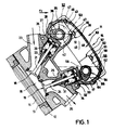
- Figure 1 is a cross-sectional view taken through the cylinder head of an internal combustion engine constructed in accordance with an embodiment of the invention and is taken generally along the line 1-1 of Figure 2.
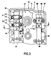
- Figure 2 is a top plan view of a portion of the cylinder head with the cam cover removed and a portion broken away to more clearly show the construction.
- Referring now in detail to the drawings, an internal combustion engine constructed in accordance with an embodiment of the invention is shown partially and is identified generally by the
reference numeral 11. Since the invention deals primarily with the valve train and lubricating system for it, only this portion of the engine has been illustrated. The remaining components of the engine may be considered to be conventional or those which are well known to those skilled in the art. - The
engine 11 includes acylinder block 12 that has one ormore cylinder bore 13. In the illustrated embodiment, thecylinder block 12 is disposed so that thecylinder bores 13 are inclined to the vertical as in conjunction with a slanted engine or one cylinder bank of a V type engine. Although the invention has particular utility in conjunction with engines wherein the cylinder bores are so oriented. The invention may also be employed in conjunction with engines having vertically aligned cylinder bores, as will become apparent to those skilled in the art. In the illustrated embodiment theengine 11 is slanted toward the front of an associated vehicle as indicated by the arrow Fr. - Pistons 14 are slidably supported within the
cylinder bores 13 and are connected by means of connecting rods (not shown) to a camshaft in a well known manner. - A cylinder head assembly, indicated generally by the
reference numeral 15 is affixed to thecylinder block 12 in any known manner and is formed withindividual recesses 16 that cooperate with each of thecylinder bores 13 andpistons 14 to form a combustion chamber of any desired configuration. - The
cylinder head assembly 15 includes a maincylinder head casting 17 in which therecesses 16 are formed and which slidably support a plurality ofintake valves 18. In the illustrated embodiment, there are provided three intake valves percylinder bore 13. In addition, on generally the opposite side of thecylinder head 17 there are slidably supported twoexhaust valves 19. Theintake valve 18 andexhaust valves 19 may be disposed in an orientation as shown and described in United States Letters Patent 4,660,529, entitled "Four Cycle Engine", issued April 28, 1987 in the name of Masaaki Yoshikawa and assigned to the Assignee of this application. It is to be understood, however, that the invention may be employed with engines having other numbers of intake and exhaust valves per cylinder. - The
intake valves 18 havevalve stems 21 that are slidably supported inguides 22 that are pressed into thecylinder head casting 17 and which control the flow of an intake charge from a suitable charge former (not shown) through one ormore intake passageways 23 into the combustion chamber formed by therecess 16. - In a like manner, the
exhaust valves 19 havestem portions 24 that are slidably supported withinguides 25 and which control the discharge of exhaust gases from thecombustion chamber 16 to the atmosphere throughexhaust ports 25 and an appropriate exhaust system (not shown). - The
intake valves 18 are each surrounded bycoil compression springs 26 that act against thecylinder head casting 17 and akeeper retainer assembly 27 for urging theintake valves 18 to their closed position. Theintake valves 18 are opened by means of an actuating mechanism, to be described, which includes thimble tappets 28 that are slidably supported within bores 29 formed in thecylinder head casting 17 and which cooperate with the tips of thevalve stems 21 in a known manner. - In a similar manner, the
exhaust valves 19 are urged to their closed position by means ofcoil compression springs 31 that encircle theirstems 24 and which act against keeper retainedassemblies 32 and thecylinder head casting 17 for urging theexhaust valves 19 to their closed positions.Thimble tappets 33 are slidably supported in bores 34 formed in thecylinder head casting 17 for opening theexhaust valves 19 in a manner which will be described. - An
intake camshaft 35 is supported within thecylinder head assembly 15 and hasindividual cam lobes intake valves 21 of therespective cylinder bore 13. Bearing surfaces are formed on theintake camshaft 35 between thecam lobes bearing assemblies intake camshaft 35 in thecylinder head assembly 15. - The
bearing assemblies surfaces cylinder head casting 17 and with bearing caps 44 and 45 that are affixed to thecylinder head casting 17 by means ofstuds 46 andnuts 47. - In accordance with conventional practice, oil passages may be formed in the cylinder head for delivering oil to the interior of the
camshaft 35 where it is delivered to thebearing assemblies - It should be noted that the
cylinder head casting 17 is provided with a construction for forming anoil well 48 and associated with thecam lobes wells 48 are formed by means ofupstanding walls 49 formed integrally with thecylinder head casting 17 and which cooperate with awall 51 formed by the bearing caps 44 and 45 so that the bearing caps 44 and 45 andwall 51 form a unitary assembly. Lubricant will fill within thewells 48 to a level indicated by theline 52 when the engine is running so as to trap lubricant in the area of thecam lobes bearing assemblies walls 51 and can be returned back to the lubricant sump through the normal return drains in the cylinder head 17 (not shown)> - It will be seen that the
cam lobes line 53 in Figure 1 which will successively immerse and remove thecam lobes wells 48 will trap lubricant. This trapped lubricant will insure lubrication of not only thecam lobes - An exhaust camshaft, indicated generally by the
reference numeral 54 is journaled within thecylinder head assembly 15 in a manner to be described and has pairs ofcam lobes thimble tappets 33 associated with theexhaust valves 19 for opening these exhaust valves. Theexhaust camshaft 54 is journaled by individual bearing assemblies, indicated generally by thereference numeral 57 which cooperate with bearing surfaces formed between theindividual cam lobes bearing surface 58 formed integrally by thecylinder head casting 17 and abearing cap 59 that is affixed to thecylinder head casting 17 by means ofstuds 61 and nuts 62. Since there is only one bearingassembly 57 associated with each cylinder of theexhaust camshaft 54 while there are twobearing assemblies intake camshaft 35 associated with each cylinder, thestuds 61 and nuts 62 are made of a larger diameter than thestuds 46 andnuts 47 associated with theintake camshaft 35 so as to insure good hold down relationship. - The valve assembly now described is contained within a cam tower recess 63 formed by the cylinder head assembly and which is closed by means of a cam cover 64 that is affixed to the
cylinder head casting 17 in a known manner. The inclined configuration of thecylinder head assembly 15 also forms a well 65 that is in proximity to thebearings 59 andcam lobes bearing assembly 59 can accumulate to a level shown by the line 66 in Figure 1. Therefore, like the wells associated with the intake camshaft tappets and bearing surfaces, lubricant will accumulate during running and also will be maintained in this area when the engine is shut down so as to insure immediate lubrication when the engine is restarted. - It is to be understood that the foregoing description is that of a preferred embodiment of the invention and that various changes and modifications may be made without departing from the spirit and scope of the invention, as defined by the appended claims.
Claims (9)
Applications Claiming Priority (2)
| Application Number | Priority Date | Filing Date | Title |
|---|---|---|---|
| JP312355/88 | 1988-12-09 | ||
| JP63312355A JP2911463B2 (en) | 1988-12-09 | 1988-12-09 | Lubrication structure of valve train |
Publications (4)
| Publication Number | Publication Date |
|---|---|
| EP0377829A2 true EP0377829A2 (en) | 1990-07-18 |
| EP0377829A3 EP0377829A3 (en) | 1990-08-16 |
| EP0377829B1 EP0377829B1 (en) | 1992-07-22 |
| EP0377829B2 EP0377829B2 (en) | 1998-03-11 |
Family
ID=18028248
Family Applications (1)
| Application Number | Title | Priority Date | Filing Date |
|---|---|---|---|
| EP19890122720 Expired - Lifetime EP0377829B2 (en) | 1988-12-09 | 1989-12-08 | Camshaft lubrication system for an internal-combustion engine |
Country Status (3)
| Country | Link |
|---|---|
| EP (1) | EP0377829B2 (en) |
| JP (1) | JP2911463B2 (en) |
| DE (1) | DE68902226T3 (en) |
Cited By (3)
| Publication number | Priority date | Publication date | Assignee | Title |
|---|---|---|---|---|
| EP0821144A1 (en) * | 1996-07-26 | 1998-01-28 | Dr.Ing.h.c. F. Porsche Aktiengesellschaft | Cylinder head arrangement of an internal combustion engine |
| WO2015104499A1 (en) | 2014-01-13 | 2015-07-16 | Rdmo | Internal combustion engine comprising cam lubrication troughs |
| US10309563B2 (en) | 2013-11-12 | 2019-06-04 | Bayerische Motoren Werke Aktiengesellschaft | Drive unit, internal combustion engine, spacer element for a fluid line arrangement, and tool kit for mounting a spacer element |
Families Citing this family (3)
| Publication number | Priority date | Publication date | Assignee | Title |
|---|---|---|---|---|
| JP2546615Y2 (en) * | 1990-12-28 | 1997-09-03 | 富士重工業株式会社 | Cam lubrication device for DOHC engine |
| JP4355633B2 (en) * | 2004-08-23 | 2009-11-04 | 株式会社クボタ | Overhead valve engine |
| JP5135052B2 (en) * | 2008-05-08 | 2013-01-30 | ヤマハ発動機株式会社 | Engine and scooter type motorcycles |
Family Cites Families (5)
| Publication number | Priority date | Publication date | Assignee | Title |
|---|---|---|---|---|
| DE2737901C2 (en) * | 1977-08-23 | 1983-01-05 | Dr.Ing.H.C. F. Porsche Ag, 7000 Stuttgart | Housing for a camshaft of an internal combustion engine for motor vehicles |
| US4329949A (en) * | 1980-06-30 | 1982-05-18 | Ford Motor Company | Cylinder head for an internal-combustion engine |
| US4660529A (en) * | 1981-04-22 | 1987-04-28 | Yamaha Hatsudoki Kabushiki Kaisha | Four-cycle engine |
| JPS62105314U (en) * | 1985-12-21 | 1987-07-04 | ||
| JP2527312B2 (en) * | 1986-10-03 | 1996-08-21 | ヤマハ発動機株式会社 | Cylinder block structure of V type engine |
-
1988
- 1988-12-09 JP JP63312355A patent/JP2911463B2/en not_active Expired - Fee Related
-
1989
- 1989-12-08 DE DE68902226T patent/DE68902226T3/en not_active Expired - Fee Related
- 1989-12-08 EP EP19890122720 patent/EP0377829B2/en not_active Expired - Lifetime
Cited By (5)
| Publication number | Priority date | Publication date | Assignee | Title |
|---|---|---|---|---|
| EP0821144A1 (en) * | 1996-07-26 | 1998-01-28 | Dr.Ing.h.c. F. Porsche Aktiengesellschaft | Cylinder head arrangement of an internal combustion engine |
| US10309563B2 (en) | 2013-11-12 | 2019-06-04 | Bayerische Motoren Werke Aktiengesellschaft | Drive unit, internal combustion engine, spacer element for a fluid line arrangement, and tool kit for mounting a spacer element |
| WO2015104499A1 (en) | 2014-01-13 | 2015-07-16 | Rdmo | Internal combustion engine comprising cam lubrication troughs |
| FR3016409A1 (en) * | 2014-01-13 | 2015-07-17 | Rdmo | EXPLOSION ENGINE COMPRISING CAM LUBRICATION AUGETS |
| CN106030055A (en) * | 2014-01-13 | 2016-10-12 | Rdmo公司 | Internal combustion engine including cam lubrication grooves |
Also Published As
| Publication number | Publication date |
|---|---|
| DE68902226T2 (en) | 1992-12-10 |
| EP0377829B1 (en) | 1992-07-22 |
| EP0377829A3 (en) | 1990-08-16 |
| DE68902226D1 (en) | 1992-08-27 |
| EP0377829B2 (en) | 1998-03-11 |
| JPH02157408A (en) | 1990-06-18 |
| DE68902226T3 (en) | 1998-06-10 |
| JP2911463B2 (en) | 1999-06-23 |
Similar Documents
| Publication | Publication Date | Title |
|---|---|---|
| US6357407B2 (en) | Anti-rotation valve lifter guide apparatus | |
| US5186129A (en) | Intermittent oiling system for an internal combustion engine camshaft and valve train | |
| US5161495A (en) | Lubrication arrangement for engine | |
| CA2056124A1 (en) | Valve gear oiling system for overhead camshaft engine | |
| EP0654589B1 (en) | Cylinder head lubricating system of an internal combustion engine | |
| US4991549A (en) | Camshaft lubricating system for engine | |
| EP0377829B1 (en) | Camshaft lubrication system for an internal-combustion engine | |
| USRE35382E (en) | Lubrication arrangement for engine | |
| US5704330A (en) | Cylinder head arrangement for internal combustion engine | |
| JPS61241411A (en) | Valve train in SOHC internal combustion engine | |
| US3033314A (en) | Internal combustion engine lubricating system | |
| US20020117020A1 (en) | Camshaft lubrication system and method of construction thereof | |
| US5325826A (en) | Journal bearing oil diverter | |
| JP2950094B2 (en) | Internal combustion engine lubrication system | |
| JPS6210409Y2 (en) | ||
| JPS59226217A (en) | Lubrication system for valve train in internal combustion engine | |
| US4433657A (en) | Modification of an internal combustion engine so as to operate permanently with a reduced number of cylinders | |
| JPH0744727Y2 (en) | Camshaft bearing structure of internal combustion engine | |
| EP0608557B1 (en) | Internal combustion engine | |
| US6209507B1 (en) | Valve mechanism for internal combustion engine | |
| JPS581610Y2 (en) | Overhead valve engine lubrication system | |
| JPS62279219A (en) | Engine block structure | |
| JPS6139051Y2 (en) | ||
| JPS59126012A (en) | Lubricating device for hydraulic valve lifter | |
| JPS6211293Y2 (en) |
Legal Events
| Date | Code | Title | Description |
|---|---|---|---|
| PUAI | Public reference made under article 153(3) epc to a published international application that has entered the european phase |
Free format text: ORIGINAL CODE: 0009012 |
|
| PUAL | Search report despatched |
Free format text: ORIGINAL CODE: 0009013 |
|
| AK | Designated contracting states |
Kind code of ref document: A2 Designated state(s): DE ES FR GB IT |
|
| AK | Designated contracting states |
Kind code of ref document: A3 Designated state(s): DE ES FR GB IT |
|
| 17P | Request for examination filed |
Effective date: 19901224 |
|
| 17Q | First examination report despatched |
Effective date: 19910328 |
|
| GRAA | (expected) grant |
Free format text: ORIGINAL CODE: 0009210 |
|
| ITF | It: translation for a ep patent filed | ||
| AK | Designated contracting states |
Kind code of ref document: B1 Designated state(s): DE ES FR GB IT |
|
| REF | Corresponds to: |
Ref document number: 68902226 Country of ref document: DE Date of ref document: 19920827 |
|
| ET | Fr: translation filed | ||
| PLBI | Opposition filed |
Free format text: ORIGINAL CODE: 0009260 |
|
| PLBI | Opposition filed |
Free format text: ORIGINAL CODE: 0009260 |
|
| 26 | Opposition filed |
Opponent name: BAYERISCHE MOTOREN WERKE AG, PATENTABTEILUNG AJ-30 Effective date: 19930403 |
|
| 26 | Opposition filed |
Opponent name: BAYERISCHE MOTOREN WERKE AG, PATENTABTEILUNG AJ-30 Effective date: 19930403 Opponent name: DR. ING. H. C. F. PORSCHE AKTIENGESELLSCHAFT Effective date: 19930420 |
|
| APAC | Appeal dossier modified |
Free format text: ORIGINAL CODE: EPIDOS NOAPO |
|
| APAC | Appeal dossier modified |
Free format text: ORIGINAL CODE: EPIDOS NOAPO |
|
| PGFP | Annual fee paid to national office [announced via postgrant information from national office to epo] |
Ref country code: ES Payment date: 19961228 Year of fee payment: 8 |
|
| APAC | Appeal dossier modified |
Free format text: ORIGINAL CODE: EPIDOS NOAPO |
|
| PLAW | Interlocutory decision in opposition |
Free format text: ORIGINAL CODE: EPIDOS IDOP |
|
| PGFP | Annual fee paid to national office [announced via postgrant information from national office to epo] |
Ref country code: GB Payment date: 19971201 Year of fee payment: 9 |
|
| PUAH | Patent maintained in amended form |
Free format text: ORIGINAL CODE: 0009272 |
|
| STAA | Information on the status of an ep patent application or granted ep patent |
Free format text: STATUS: PATENT MAINTAINED AS AMENDED |
|
| 27A | Patent maintained in amended form |
Effective date: 19980311 |
|
| AK | Designated contracting states |
Kind code of ref document: B2 Designated state(s): DE ES FR GB IT |
|
| ITF | It: translation for a ep patent filed | ||
| PG25 | Lapsed in a contracting state [announced via postgrant information from national office to epo] |
Ref country code: ES Free format text: LAPSE BECAUSE OF FAILURE TO SUBMIT A TRANSLATION OF THE DESCRIPTION OR TO PAY THE FEE WITHIN THE PRESCRIBED TIME-LIMIT Effective date: 19980622 |
|
| ET3 | Fr: translation filed ** decision concerning opposition | ||
| PG25 | Lapsed in a contracting state [announced via postgrant information from national office to epo] |
Ref country code: GB Free format text: LAPSE BECAUSE OF NON-PAYMENT OF DUE FEES Effective date: 19981208 |
|
| GBPC | Gb: european patent ceased through non-payment of renewal fee |
Effective date: 19981208 |
|
| APAH | Appeal reference modified |
Free format text: ORIGINAL CODE: EPIDOSCREFNO |
|
| PGFP | Annual fee paid to national office [announced via postgrant information from national office to epo] |
Ref country code: DE Payment date: 20061130 Year of fee payment: 18 |
|
| PGFP | Annual fee paid to national office [announced via postgrant information from national office to epo] |
Ref country code: FR Payment date: 20061208 Year of fee payment: 18 |
|
| PG25 | Lapsed in a contracting state [announced via postgrant information from national office to epo] |
Ref country code: DE Free format text: LAPSE BECAUSE OF NON-PAYMENT OF DUE FEES Effective date: 20080701 |
|
| REG | Reference to a national code |
Ref country code: FR Ref legal event code: ST Effective date: 20081020 |
|
| PG25 | Lapsed in a contracting state [announced via postgrant information from national office to epo] |
Ref country code: FR Free format text: LAPSE BECAUSE OF NON-PAYMENT OF DUE FEES Effective date: 20071231 |
|
| PGFP | Annual fee paid to national office [announced via postgrant information from national office to epo] |
Ref country code: IT Payment date: 20081229 Year of fee payment: 20 |