EP0377201A2 - Self locking screw connection - Google Patents
Self locking screw connection Download PDFInfo
- Publication number
- EP0377201A2 EP0377201A2 EP89123943A EP89123943A EP0377201A2 EP 0377201 A2 EP0377201 A2 EP 0377201A2 EP 89123943 A EP89123943 A EP 89123943A EP 89123943 A EP89123943 A EP 89123943A EP 0377201 A2 EP0377201 A2 EP 0377201A2
- Authority
- EP
- European Patent Office
- Prior art keywords
- thread
- screw connection
- nut
- bolt
- flank
- Prior art date
- Legal status (The legal status is an assumption and is not a legal conclusion. Google has not performed a legal analysis and makes no representation as to the accuracy of the status listed.)
- Granted
Links
- 238000004519 manufacturing process Methods 0.000 description 8
- 238000006073 displacement reaction Methods 0.000 description 1
- 238000012544 monitoring process Methods 0.000 description 1
- 230000036316 preload Effects 0.000 description 1
Images

Classifications
-
- F—MECHANICAL ENGINEERING; LIGHTING; HEATING; WEAPONS; BLASTING
- F16—ENGINEERING ELEMENTS AND UNITS; GENERAL MEASURES FOR PRODUCING AND MAINTAINING EFFECTIVE FUNCTIONING OF MACHINES OR INSTALLATIONS; THERMAL INSULATION IN GENERAL
- F16B—DEVICES FOR FASTENING OR SECURING CONSTRUCTIONAL ELEMENTS OR MACHINE PARTS TOGETHER, e.g. NAILS, BOLTS, CIRCLIPS, CLAMPS, CLIPS OR WEDGES; JOINTS OR JOINTING
- F16B39/00—Locking of screws, bolts or nuts
- F16B39/22—Locking of screws, bolts or nuts in which the locking takes place during screwing down or tightening
- F16B39/28—Locking of screws, bolts or nuts in which the locking takes place during screwing down or tightening by special members on, or shape of, the nut or bolt
- F16B39/30—Locking exclusively by special shape of the screw-thread
Definitions
- the present invention relates to a self-locking screw connection according to the preamble of claim 1.
- Such self-locking screw connections are known. They generate the frictional engagement required to secure the screw connection by means of a bracing brought about by means of an applied torque.
- different thread shapes are carried out on the bolt, a section with a regular thread at the free end and a section with a securing thread preferably being arranged thereafter.
- Such designs are described in DE-OS 25 27 557, DE-AS 23 65 132, DE-OS 26 45 519, DE-OS 27 14 180 and DE-AS 17 50 206.
- the securing thread has a geometric shape that deviates from the standard thread, with deviations in the pitch in the form of the thread root and the flank diameter being made, for example.
- Versions with two different types of thread on one bolt are naturally difficult to manufacture and correspondingly expensive. You need special tools for both cutting and non-cutting production.
- the position of the nut on the bolt in the clamped state is determined by the length dimensions of the two threaded sections, so that when fastening flat bodies of different thicknesses, a large number of differently designed special bolts must be kept available by such a screw connection, which in turn increases the cost of warehousing.
- the nut can only be screwed on on one side.
- Another embodiment of self-locking screw connections has a uniform thread on the bolt, whereby the last-mentioned disadvantages of the first embodiment are eliminated.
- DE-OS 26 25 997 describes a safety thread, screws and nut threads having different lead angles.
- DE-OS 29 03 845 describes a screw connection with a securing thread which has different flank angles, a flattened thread core, different thread depth and a longitudinal distance between the thread flanks in the area of the thread tips or the thread core.
- DE-OS 36 01 389 describes a connecting element in which the screw thread has a different pitch. Furthermore, such a screw-in depth is to be provided between the two machine elements screw / nut that the required frictional torque arises.
- the object of the present invention is accordingly to create a self-locking screw connection which is simple and inexpensive to produce and can be used without restriction.
- connection of the nut and bolt is free of play is so that there is no relative movement in the thread. This makes the connection self-locking. This self-locking can also be used for high-strength connections because all thread flanks bear the same as with a regular thread.
- Another advantage of the screw connection according to the invention lies in the simple manufacture.
- the nut outer diameter and core diameter are also produced according to the standard thread dimensions, only the flank diameter is reduced.
- the flank diameter of the nut has the same dimension as the flank diameter of the bolt, in particular the smallest dimension of the flank diameter of the regular thread of the bolt.
- the bolt outer and core diameters are also produced according to the standard thread dimensions, only the flank diameter is increased.
- the same dimension is chosen for the flank diameter of the bolt as for the flank diameter of the nut, in particular the largest dimension of the flank diameter of the standard thread of the nut.
- flank diameter of the securing thread is largely freely selectable and therefore adaptable to the application.
- the choice of the tolerance position can thus influence the screwing torque and the preload force.
- Production can be easily controlled by monitoring the diameter.
- the materials of screws and nuts of the screw connection according to the invention can be the same as for the standard thread. It is of course possible to provide different material pairings if this is required for special application reasons.
- the flanks between the bolt thread and the nut thread can have a backlash less than or equal to zero, with a backlash less than zero further improving the securing.
- a non-load-bearing flank side of the bolt thread and / or the nut thread deviates from a straight line in longitudinal section. This ensures that this flank side touches the counter flank on a relatively small surface and the friction conditions are improved without impairing the load-bearing capacity of the threaded connection.
- the flank side deviating from a straight line in longitudinal section is preferably convex in longitudinal section, the flank being approximately in the area of the flank diameter touches the counter flank.
- a standard thread for example a metric thread
- DIN has an outer diameter d, a flank diameter d2 and a core diameter d1, based on the bolt thread of a bolt 10.
- An associated nut 11 also has outer, flank and core diameters, which are not shown, since they belong to the general prior art.
- tensile forces represented by arrows “FZug” act on the connection and bring the loaded thread flanks into abutment, a backlash 13 occurring on the unloaded side of the thread flanks.
- the geometrical dimensions d, d1, d2 are prescribed for standardized screw connections, which ensures the corresponding backlash.
- a thread described according to a standard is referred to in the following text as a standard thread.
- DIN standards can be metric threads, metric fine threads, Whitworth threads, trapezoidal threads or other threads.
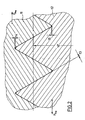
- a screw connection according to the invention has the screw bolt 12 and the associated nut 11, the flank diameter d2 'according to the invention deviating from the flank diameter d2 of a standard thread.
- the dimension of the flank diameter d2 ' is chosen so that there is a backlash 13 of zero in the unloaded and of course also loaded state of the screw connection.
- a head play 14 and a foot play 15 of the screw connection corresponds essentially to that of a standard thread in the embodiment according to the invention.
- a different dimension from the standard thread is also possible, in any case it must be ensured that there is sufficient head and foot play.
- the nut 11 corresponds to the previously described nut.
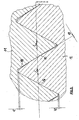
- the bolt 12 has two unequal thread flanks, one upon application of a tensile force F train carrying edge 16 in a longitudinal section a straight configuration and a non-load bearing flank 17 in longitudinal section with a radius, ie is convex.
- the non-load-bearing flank 17 is thus on a counter flank 18 of the nut 11, so that there is zero backlash 13 in the unloaded and loaded state of the screw connection.
- a head play 14 and a foot play 15 corresponding to the screw connection according to FIG. 2 are also provided.
- Manufacturing tolerances of nut 11 and bolt 12 are compensated for in this screw connection by material displacement into the gap between non-load-bearing flank 17 and counter flank 18, so that uniform frictional relationships are achieved.
Abstract
Description
Die vorliegende Erfindung betrifft eine selbstsichernde Schraubverbindung nach dem Oberbegriff des Anspruchs 1.The present invention relates to a self-locking screw connection according to the preamble of claim 1.
Solche selbstsichernden Schraubverbindungen sind bekannt. Sie erzeugen den zur Sicherung der Schraubverbindung erforderlichen Reibschluß durch eine mittels aufgebrachtem Drehmoment herbeigeführte Verspannung. Dazu werden in der einen Ausführungsart solcher Verbindungen unterschiedliche Gewindeformen auf dem Bolzen ausgeführt, wobei vorzugsweise ein Abschnitt mit Regelgewinde am freien Ende und ein Abschnitt mit Sicherungsgewinde daran anschließend angeordnet sind. Solche Ausführungen sind in der DE-OS 25 27 557, DE-AS 23 65 132, DE-OS 26 45 519, DE-OS 27 14 180 und DE-AS 17 50 206 beschrieben.Such self-locking screw connections are known. They generate the frictional engagement required to secure the screw connection by means of a bracing brought about by means of an applied torque. For this purpose, in one embodiment of such connections, different thread shapes are carried out on the bolt, a section with a regular thread at the free end and a section with a securing thread preferably being arranged thereafter. Such designs are described in DE-OS 25 27 557, DE-AS 23 65 132, DE-OS 26 45 519, DE-OS 27 14 180 and DE-AS 17 50 206.
Das Sicherungsgewinde weist in den oben angeführten Schriften eine vom Regelgewinde abweichende geometrische Form auf, wobei zum Beispiel Abweichungen in der Ganghöhe in der Form des Gewindegrundes und des Flankendurchmessers vorgenommen werden.In the above-mentioned documents, the securing thread has a geometric shape that deviates from the standard thread, with deviations in the pitch in the form of the thread root and the flank diameter being made, for example.
Ausführungen mit zwei unterschiedlichen Gewindearten auf einem Bolzen sind naturgemäß schwierig herzustellen und entsprechend kostenaufwendig. Sie benötigen Spezialwerkzeuge sowohl bei spanender als auch bei spanloser Fertigung. Außerdem ist die Position der Mutter auf dem Bolzen in verspantem Zustand durch die Längenmaße der beiden Gewindeabschnitte festgelegt, so daß bei Befestigung verschieden dicker flächiger Körper durch eine solche Schraubverbindung eine große Anzahl von unterschiedlich ausgeführten Spezialbolzen vorgehalten werden müssen, was wiederum die Lagerhaltung verteuert. Außerdem kann bei Gewindestiften die Mutter nur einseitig aufgeschraubt werden.Versions with two different types of thread on one bolt are naturally difficult to manufacture and correspondingly expensive. You need special tools for both cutting and non-cutting production. In addition, the position of the nut on the bolt in the clamped state is determined by the length dimensions of the two threaded sections, so that when fastening flat bodies of different thicknesses, a large number of differently designed special bolts must be kept available by such a screw connection, which in turn increases the cost of warehousing. In addition, the nut can only be screwed on on one side.
Eine andere Ausführungsart selbstsichernder Schraubverbindungen weist ein einheitliches Gewinde auf dem Bolzen auf, wodurch die zuletzt genannten Nachteile der ersten Ausführungsart entfallen.Another embodiment of self-locking screw connections has a uniform thread on the bolt, whereby the last-mentioned disadvantages of the first embodiment are eliminated.
Solche Schraubverbindungen sind in der DE-OS 26 25 997, DE-OS 29 03 845 und DE-OS 36 01 389 beschrieben.Such screw connections are described in DE-OS 26 25 997, DE-OS 29 03 845 and DE-OS 36 01 389.
Die bekannten Schraubverbindungen weisen einige Nachteile auf.The known screw connections have some disadvantages.
Die DE-OS 26 25 997 beschreibt ein Sicherheitsgewinde, wobei Schrauben und Mutterngewinde unterschiedliche Steigungswinkel aufweisen. Zur Herstellung von Gewinden mit Steigungswinkeln, die von der Norm abweichen, ist in jedem Fall der Einsatz von Sonderwerkzeugen und/oder Sonderprogrammen auf Werkzeugmaschinen erforderlich, was zu höherem Zeitaufwand und höheren Kosten gegenüber einer Herstellung von Normgewinden führt.DE-OS 26 25 997 describes a safety thread, screws and nut threads having different lead angles. To produce threads with lead angles that deviate from the standard, the use of special tools and / or special programs on machine tools is required in any case, which leads to a higher expenditure of time and higher costs than the production of standard threads.
Die DE-OS 29 03 845 beschreibt eine Schraubverbindung mit einem Sicherungsgewinde, das unterschiedliche Flankenwinkel, einen abgeflachten Gewindekern, abweichende Gewindetiefe und einen Längsabstand zwischen den Gewindeflanken im Bereich der Gewindespitzen bzw. des Gewindekerns aufweist.DE-OS 29 03 845 describes a screw connection with a securing thread which has different flank angles, a flattened thread core, different thread depth and a longitudinal distance between the thread flanks in the area of the thread tips or the thread core.
Es liegt auf der Hand, daß die Herstellung eines so weit von der Norm abweichenden Gewindes noch in weit größerem Maße als in der zuvor genannten Druckschrift den Einsatz aufwendiger Werkzeuge und Herstellungsverfahren erfordert.It is obvious that the production of a thread that differs so far from the norm is even larger Dimensions than in the aforementioned document requires the use of expensive tools and manufacturing processes.
Die DE-OS 36 01 389 beschreibt ein Verbindungselement, bei dem das Schraubengewinde eine abweichende Steigung aufweist. Weiterhin ist zwischen den beiden Maschinenelementen Schraube/Mutter eine solche Einschraubtiefe vorzusehen, daß das erforderliche Reibmoment entsteht.DE-OS 36 01 389 describes a connecting element in which the screw thread has a different pitch. Furthermore, such a screw-in depth is to be provided between the two machine elements screw / nut that the required frictional torque arises.
Auch in diesem Falle treffen die mit dem Einsatz von Sonderwerkzeugen verbundenen Nachteile zu, wobei zusätzlich die Einschraubtiefe und damit die Bauhöhe der Mutter als ein die Verwendungsmöglichkeit einschränkendes Merkmal genannt wird.In this case too, the disadvantages associated with the use of special tools apply, the screw-in depth and thus the overall height of the nut additionally being mentioned as a feature restricting the possible use.
Aufgabe der vorliegenden Erfindung ist demnach, eine selbstsichernde Schraubverbindung zu erstellen, die einfach und kostengünstig herstellbar und ohne Einschränkung einsetzbar ist.The object of the present invention is accordingly to create a self-locking screw connection which is simple and inexpensive to produce and can be used without restriction.
Die Aufgabe wird durch die Merkmale des kennzeichnenden Teils des Anspruchs 1 gelöst.The object is achieved by the features of the characterizing part of claim 1.
Der Vorteil der erfindungsgemäßen Schraubverbindung liegt darin, daß die Verbindung von Mutter und Bolzen spielfrei ist, so daß keine Relativbewegung im Gewinde entsteht. Dadurch ist die Verbindung selbstsichernd. Diese Selbstsicherung kann auch bei hochfesten Verbindungen eingesetzt werden, weil alle Gewindeflanken genauso tragen wie bei einem Regelgewinde.The advantage of the screw connection according to the invention is that the connection of the nut and bolt is free of play is so that there is no relative movement in the thread. This makes the connection self-locking. This self-locking can also be used for high-strength connections because all thread flanks bear the same as with a regular thread.
Ein weiterer Vorteil der erfindungsgemäßen Schraubverbindung liegt in der einfachen Herstellung.Another advantage of the screw connection according to the invention lies in the simple manufacture.
Es können wahlweise der Bolzen mit Regelgewinde und die Mutter mit Sicherungsgewinde oder die Mutter mit Regelgewinde und der Bolzen mit Sicherungsgewinde hergestellt werden.You can choose between the bolt with the regular thread and the nut with the locking thread or the nut with the regular thread and the bolt with the locking thread.
Soll der Bolzen mit Regelgewinde hergestellt werden, so werden der Mutteraußendurchmesser und Kerndurchmesser auch nach den Regelgewindemaßen hergestellt, nur wird der Flankendurchmesser verkleinert. In einer Ausgestaltung der Erfindung ist vorgesehen, daß bei Verwendung eines Bolzens mit Regelgewinde der Flankendurchmesser der Mutter das gleiche Maß aufweist wie der Flankendurchmesser des Bolzens, insbesondere das Kleinstmaß des Flankendurchmessers des Regelgewindes vom Bolzen.If the bolt is to be produced with a standard thread, the nut outer diameter and core diameter are also produced according to the standard thread dimensions, only the flank diameter is reduced. In one embodiment of the invention it is provided that when using a bolt with a regular thread the flank diameter of the nut has the same dimension as the flank diameter of the bolt, in particular the smallest dimension of the flank diameter of the regular thread of the bolt.
Soll die Mutter mit Regelgewinde und der Bolzen mit Siche rungsgewinde hergestellt werden, so werden Bolzenaußen- und Kerndurchmesser auch nach den Regelgewindemaßen hergestellt, nur der Flankendurchmesser wird vergrößert. In einer Ausgestaltung der Erfindung ist vorgesehen, daß hierbei für den Flankendurchmesser des Bolzens das gleiche Maß gewählt wird wie für den Flankendurchmesser der Mutter, insbesondere das Größtmaß des Flankendurchmessers des Regelgewindes von der Mutter.Should the nut with regular thread and the bolt with siche thread are produced, the bolt outer and core diameters are also produced according to the standard thread dimensions, only the flank diameter is increased. In one embodiment of the invention it is provided that the same dimension is chosen for the flank diameter of the bolt as for the flank diameter of the nut, in particular the largest dimension of the flank diameter of the standard thread of the nut.
Natürlich ist das Abmaß des Flankendurchmessers des Sicherungsgewindes weitgehend frei wählbar und damit der Anwendung anpaßbar.Durch die Wahl der Toleranzlage können somit das Einschraubmoment und die Vorspannkraft beeinflußt werden.Of course, the dimension of the flank diameter of the securing thread is largely freely selectable and therefore adaptable to the application. The choice of the tolerance position can thus influence the screwing torque and the preload force.
Die Produktion kann durch Überwachung der Durchmesser einfach kontrolliert werden.Production can be easily controlled by monitoring the diameter.
Die Werkstoffe von Schrauben und Muttern der erfindungsgemäßen Schraubverbindung können die gleichen wie beim Regelgewinde sein. Es ist natürlich möglich, abweichende Materialpaarungen vorzusehen, wenn das aus besonderen Anwendungsgründen benötigt wird.The materials of screws and nuts of the screw connection according to the invention can be the same as for the standard thread. It is of course possible to provide different material pairings if this is required for special application reasons.
Die Flanken zwischen Bolzengewinde und Mutterngewinde können ein Flankenspiel kleiner oder gleich Null aufweisen, wobei ein Flankenspiel kleiner Null die Sicherung weiter verbessert.The flanks between the bolt thread and the nut thread can have a backlash less than or equal to zero, with a backlash less than zero further improving the securing.
Bei einer weiteren Ausgestaltung weicht eine nicht tragende Flankenseite des Bolzengewindes und/oder des Mutterngewindes im Längsschnitt von einer Geraden ab. Hierdurch wird erreicht, daß diese Flankenseite auf einer relativ geringen Fläche die Gegenflanke berührt und werden die Reibverhältnisse verbessert, ohne die Tragfähigkeit der Gewindeverbindung zu beeinträchtigen.Bevorzugt ist die im Längsschnitt von einer Geraden abweichende Flankenseite im Längsschnitt konvex ausgebildet, wobei die Flanke etwa im Bereich des Flankendurchmessers die Gegenflanke berührt.In a further embodiment, a non-load-bearing flank side of the bolt thread and / or the nut thread deviates from a straight line in longitudinal section. This ensures that this flank side touches the counter flank on a relatively small surface and the friction conditions are improved without impairing the load-bearing capacity of the threaded connection. The flank side deviating from a straight line in longitudinal section is preferably convex in longitudinal section, the flank being approximately in the area of the flank diameter touches the counter flank.
Nunmehr wird die Erfindung anhand der Darstellungen näher erläutert.
- Fig. 1 ist ein schematisch dargestellter Schnitt durch ein Regelgewinde einer Schrauben-/Mutternverbindung.
- Fig. 2 ist ein schematisch dargestellter Schnitt durch ein erfindungsgemäßes Gewinde einer Schrauben-/Mutternverbindung.
- Fig. 3 ist ein schematisch dargestellter Schnitt durch ein anderes Ausführungsbeispiel eines erfindungsgemäßen Gewindes einer Schrauben-/Mutternverbindung.
- Fig. 1 is a schematically illustrated section through a standard thread of a screw / nut connection.
- Fig. 2 is a schematically illustrated section through an inventive thread of a screw / nut connection.
- Fig. 3 is a schematically illustrated section through another embodiment of a thread of a screw / nut connection according to the invention.
Bevor auf die in der Zeichnung dargestellten Einzelheiten näher eingegangen wird, sei vorangestellt, daß jedes der beschriebenen Merkmale für sich oder in Verbindung mit Merkmalen der Ansprüche von erfindungswesentlicher Bedeutung ist.Before going into the details shown in the drawing, it should be stated that each of the features described is of importance for the invention, either individually or in conjunction with features of the claims.
Aus Fig. 1 ist ersichtlich, daß ein Regelgewinde, zum Beispiel ein metrisches Gewinde, nach DIN einen Außendurchmesser d, einen Flankendurchmesser d2 und einen Kerndurchmesser d1, bezogen auf das Bolzengewinde eines Bolzens 10, aufweist. Eine zugehörige Mutter 11 weist ebenfalls Außen-, Flanken- und Kerndurchmesser auf, die nicht dargestellt sind, da sie zum allgemeinen Stand der Technik gehören. Im verspannten Zustand der Schraubverbindung aus Bolzen 10 und Mutter 11 greifen durch Pfeile "FZug" dargestellte Zugkräfte an der Verbindung an und bringen die belasteten Gewindeflanken zur Anlage, wobei auf der unbelasteten Seite der Gewindeflanken ein Flankenspiel 13 auftritt. Die geometrischen Abmessungen d, d1, d2 sind für genormte Schraubverbindungen vorgeschrieben, wodurch das entsprechende Flankenspiel sichergestellt ist. Ein nach einer Norm beschriebenes Gewinde wird im folgenden Text als Regelgewinde bezeichnet. Es kann sich dabei bei DIN-Normen um metrisches Gewinde, metrisches Feingewinde, Whitworthgewinde, Trapezgewinde oder ein sonstiges Gewinde handeln.From Fig. 1 it can be seen that a standard thread, for example a metric thread, according to DIN has an outer diameter d, a flank diameter d2 and a core diameter d1, based on the bolt thread of a
Natürlich ist der Begriff Regelgewinde auch auf Normen anderer Nationen anwendbar.Of course, the term standard thread can also be applied to standards of other nations.
In Fig. 2 weist eine erfindungsgemäße Schraubverbindung den Schraubenbolzen 12 und die zugehörige Mutter 11 auf, wobei der Flankendurchmesser d2′ erfindungsgemäß von dem Flankendurchmesser d2 eines Regelgewindes abweicht. Das Maß des Flankendurchmessers d2′ wird so gewählt, daß sich in unbelastetem und natürlich auch belastetem Zustand der Schraubverbindung ein Flankenspiel 13 von Null ergibt. Ein Kopfspiel 14 und ein Fußspiel 15 der Schraubverbindung entspricht bei der erfindungsgemäßen Ausführung im wesentlichen dem eines Regelgewindes. Natürlich ist auch eine abweichende Abmessung vom Regelgewinde möglich, es muß jedenfalls sichergestellt sein, daß ein Kopf- und Fußspiel von ausreichender Abmessung vorliegt.2, a screw connection according to the invention has the
Bei einem weiteren Ausführungsbeispiel einer erfindungsgemäßen Schraubverbindung gemäß Fig. 3 stimmt die Mutter 11 mit der zuvor beschriebenen Mutter überein. Der Schraubenbolzen 12 hingegen hat zwei ungleiche Gewindeflanken, wobei eine beim Anlegen einer Zugkraft Fzug tragende Flanke 16 im Längsschnitt gerade ausgebildet und eine nicht tragende Flanke 17 im Längsschnitt mit einem Radius, d.h. konvex geformt ist. Die nicht tragende Flanke 17 liegt somit an einer Gegenflanke 18 der Mutter 11 auf, so daß sich in unbelastetem und im belasteten Zustand der Schraubverbindung ein Flankenspiel 13 von Null ergibt. Auch sind ein Kopfspiel 14 und ein Fußspiel 15 entsprechend der Schraubverbindung gemäß Fig. 2 vorgesehen.In a further exemplary embodiment of a screw connection according to the invention according to FIG. 3, the
Fertigungstoleranzen von Mutter 11 und Bolzen 12 werden bei dieser Schraubverbindung durch Materialverdrängung in die Spalte zwischen nicht tragender Flanke 17 und Gegenflanke 18 ausgeglichen, so daß gleichmäßige Reibverhältnisse erzielt werden.Manufacturing tolerances of
Claims (7)
Applications Claiming Priority (2)
| Application Number | Priority Date | Filing Date | Title |
|---|---|---|---|
| DE3844477A DE3844477A1 (en) | 1988-12-31 | 1988-12-31 | SELF-LOCKING SCREW CONNECTION |
| DE3844477 | 1988-12-31 |
Publications (3)
| Publication Number | Publication Date |
|---|---|
| EP0377201A2 true EP0377201A2 (en) | 1990-07-11 |
| EP0377201A3 EP0377201A3 (en) | 1990-11-14 |
| EP0377201B1 EP0377201B1 (en) | 1993-09-29 |
Family
ID=6370626
Family Applications (1)
| Application Number | Title | Priority Date | Filing Date |
|---|---|---|---|
| EP89123943A Expired - Lifetime EP0377201B1 (en) | 1988-12-31 | 1989-12-27 | Self locking screw connection |
Country Status (3)
| Country | Link |
|---|---|
| EP (1) | EP0377201B1 (en) |
| DE (2) | DE3844477A1 (en) |
| ES (1) | ES2044046T3 (en) |
Cited By (1)
| Publication number | Priority date | Publication date | Assignee | Title |
|---|---|---|---|---|
| DE102010043805A1 (en) * | 2010-11-11 | 2012-06-14 | Polycom Škofja Loka D.O.O. | Self-locking adjustment device for adjusting vehicle steering, comprises primary component with internal thread, and secondary component with external thread for engaging internal thread of primary component |
Families Citing this family (2)
| Publication number | Priority date | Publication date | Assignee | Title |
|---|---|---|---|---|
| DE102010005145A1 (en) * | 2010-01-19 | 2011-07-21 | Honeywell Technologies S.A.R.L. | Plastic and metal screw drive with a threaded nut and a threaded spindle |
| DE102015110088A1 (en) * | 2015-06-23 | 2016-12-29 | Maco Technologie Gmbh | ECK BEARINGS FOR A TILT-TILT WINDOW |
Citations (3)
| Publication number | Priority date | Publication date | Assignee | Title |
|---|---|---|---|---|
| US2581690A (en) * | 1949-11-30 | 1952-01-08 | Moehle Walter | Locking thread structure |
| DE1750206A1 (en) * | 1967-04-07 | 1971-01-07 | Lamson & Sessions Co Corp Of O | Escapement screw and process for its manufacture |
| DE1750260A1 (en) * | 1968-04-13 | 1971-04-01 | Robert Zapp Fa | Composite pipe |
-
1988
- 1988-12-31 DE DE3844477A patent/DE3844477A1/en not_active Withdrawn
-
1989
- 1989-12-27 DE DE89123943T patent/DE58905778D1/en not_active Expired - Fee Related
- 1989-12-27 EP EP89123943A patent/EP0377201B1/en not_active Expired - Lifetime
- 1989-12-27 ES ES89123943T patent/ES2044046T3/en not_active Expired - Lifetime
Patent Citations (3)
| Publication number | Priority date | Publication date | Assignee | Title |
|---|---|---|---|---|
| US2581690A (en) * | 1949-11-30 | 1952-01-08 | Moehle Walter | Locking thread structure |
| DE1750206A1 (en) * | 1967-04-07 | 1971-01-07 | Lamson & Sessions Co Corp Of O | Escapement screw and process for its manufacture |
| DE1750260A1 (en) * | 1968-04-13 | 1971-04-01 | Robert Zapp Fa | Composite pipe |
Non-Patent Citations (2)
| Title |
|---|
| PRODUCT ENGINEERING * |
| PRODUCT ENGINEERING, Band 50, Nr. 4, April 1979, Seiten 55-59; "World of self-locking screw grows" * |
Cited By (1)
| Publication number | Priority date | Publication date | Assignee | Title |
|---|---|---|---|---|
| DE102010043805A1 (en) * | 2010-11-11 | 2012-06-14 | Polycom Škofja Loka D.O.O. | Self-locking adjustment device for adjusting vehicle steering, comprises primary component with internal thread, and secondary component with external thread for engaging internal thread of primary component |
Also Published As
| Publication number | Publication date |
|---|---|
| EP0377201A3 (en) | 1990-11-14 |
| DE3844477A1 (en) | 1990-07-05 |
| ES2044046T3 (en) | 1994-01-01 |
| EP0377201B1 (en) | 1993-09-29 |
| DE58905778D1 (en) | 1993-11-04 |
Similar Documents
| Publication | Publication Date | Title |
|---|---|---|
| DE2043792A1 (en) | Securing a screw nut against a screw and a screwed workpiece using a further screw nut acting as a counter nut | |
| DE3920678C2 (en) | Filter nozzle | |
| DD255766A5 (en) | REMOVABLE CONNECTING PART | |
| DE3739238A1 (en) | GAME-FREE COMPACT REDUCTION GEARBOX | |
| EP0237716A1 (en) | Connecting element of the screw/nut connection type | |
| WO2008125076A1 (en) | Leaf spring made of a fiber-plastic composite and force transmission element therefor | |
| DE1500896B1 (en) | Repeatedly detachable screw connection | |
| DE2521684A1 (en) | VIBRATION-PROOF FIXING ELEMENT | |
| WO1987004674A1 (en) | Device for stepped height-adjustment of a securing or return-travel point for a safety belt or the like | |
| DE3009716C2 (en) | Securing element for a screw nut that can be placed on a threaded bolt | |
| DD153174A5 (en) | AGAINST UNINTENDED LOESEN SECURED BOLTS, IN PARTICULAR THREADED BOLTS | |
| EP1238199A1 (en) | Screwed connection, fastener for said connection and method for the production thereof | |
| EP0377201B1 (en) | Self locking screw connection | |
| WO2008012074A1 (en) | Safety nut | |
| EP0460264A1 (en) | Screw | |
| EP0132661B1 (en) | Trigger for a contactless switch | |
| DE3822831A1 (en) | Tamper-proof fastening and tool for operating the same | |
| DE4003892A1 (en) | SELF-LOCKING THREAD | |
| DE4108175C2 (en) | FASTENING DEVICE | |
| DE202018104400U1 (en) | Combination screw | |
| DE3035119A1 (en) | Screw bolt locking system - has shank in two parts with part-cylindrical axial protrusions fitting together | |
| DE202005005756U1 (en) | Bolt with outer threads on each side of head, has pin attached to side of head opposite thread by welding | |
| DE3344240A1 (en) | Nut | |
| EP3830432B1 (en) | Combination screw | |
| DE2941887C2 (en) | Connection device for two components of buildings |
Legal Events
| Date | Code | Title | Description |
|---|---|---|---|
| PUAI | Public reference made under article 153(3) epc to a published international application that has entered the european phase |
Free format text: ORIGINAL CODE: 0009012 |
|
| AK | Designated contracting states |
Kind code of ref document: A2 Designated state(s): CH DE ES FR GB IT LI NL SE |
|
| PUAL | Search report despatched |
Free format text: ORIGINAL CODE: 0009013 |
|
| AK | Designated contracting states |
Kind code of ref document: A3 Designated state(s): CH DE ES FR GB IT LI NL SE |
|
| 17P | Request for examination filed |
Effective date: 19910508 |
|
| 17Q | First examination report despatched |
Effective date: 19920204 |
|
| GRAA | (expected) grant |
Free format text: ORIGINAL CODE: 0009210 |
|
| AK | Designated contracting states |
Kind code of ref document: B1 Designated state(s): CH DE ES FR GB IT LI NL SE |
|
| PG25 | Lapsed in a contracting state [announced via postgrant information from national office to epo] |
Ref country code: SE Effective date: 19930929 Ref country code: NL Effective date: 19930929 |
|
| GBT | Gb: translation of ep patent filed (gb section 77(6)(a)/1977) |
Effective date: 19931004 |
|
| REF | Corresponds to: |
Ref document number: 58905778 Country of ref document: DE Date of ref document: 19931104 |
|
| ET | Fr: translation filed | ||
| ITF | It: translation for a ep patent filed |
Owner name: STUDIO TORTA SOCIETA' SEMPLICE |
|
| PGFP | Annual fee paid to national office [announced via postgrant information from national office to epo] |
Ref country code: FR Payment date: 19931214 Year of fee payment: 5 |
|
| PGFP | Annual fee paid to national office [announced via postgrant information from national office to epo] |
Ref country code: DE Payment date: 19931217 Year of fee payment: 5 |
|
| PGFP | Annual fee paid to national office [announced via postgrant information from national office to epo] |
Ref country code: GB Payment date: 19931223 Year of fee payment: 5 |
|
| PG25 | Lapsed in a contracting state [announced via postgrant information from national office to epo] |
Ref country code: LI Effective date: 19931231 Ref country code: CH Effective date: 19931231 |
|
| REG | Reference to a national code |
Ref country code: ES Ref legal event code: FG2A Ref document number: 2044046 Country of ref document: ES Kind code of ref document: T3 |
|
| PGFP | Annual fee paid to national office [announced via postgrant information from national office to epo] |
Ref country code: ES Payment date: 19940119 Year of fee payment: 5 |
|
| NLV1 | Nl: lapsed or annulled due to failure to fulfill the requirements of art. 29p and 29m of the patents act | ||
| PLBE | No opposition filed within time limit |
Free format text: ORIGINAL CODE: 0009261 |
|
| STAA | Information on the status of an ep patent application or granted ep patent |
Free format text: STATUS: NO OPPOSITION FILED WITHIN TIME LIMIT |
|
| REG | Reference to a national code |
Ref country code: CH Ref legal event code: PL |
|
| 26N | No opposition filed | ||
| PG25 | Lapsed in a contracting state [announced via postgrant information from national office to epo] |
Ref country code: GB Effective date: 19941227 |
|
| GBPC | Gb: european patent ceased through non-payment of renewal fee |
Effective date: 19941227 |
|
| PG25 | Lapsed in a contracting state [announced via postgrant information from national office to epo] |
Ref country code: FR Effective date: 19950831 |
|
| PG25 | Lapsed in a contracting state [announced via postgrant information from national office to epo] |
Ref country code: DE Effective date: 19950901 |
|
| REG | Reference to a national code |
Ref country code: FR Ref legal event code: ST |
|
| PG25 | Lapsed in a contracting state [announced via postgrant information from national office to epo] |
Ref country code: ES Free format text: LAPSE BECAUSE OF NON-PAYMENT OF DUE FEES Effective date: 19951228 |
|
| REG | Reference to a national code |
Ref country code: ES Ref legal event code: FD2A Effective date: 19960113 |
|
| PG25 | Lapsed in a contracting state [announced via postgrant information from national office to epo] |
Ref country code: IT Free format text: LAPSE BECAUSE OF NON-PAYMENT OF DUE FEES;WARNING: LAPSES OF ITALIAN PATENTS WITH EFFECTIVE DATE BEFORE 2007 MAY HAVE OCCURRED AT ANY TIME BEFORE 2007. THE CORRECT EFFECTIVE DATE MAY BE DIFFERENT FROM THE ONE RECORDED. Effective date: 20051227 |