EP0376837B1 - Method and apparatus for holography using incoherent light - Google Patents
Method and apparatus for holography using incoherent light Download PDFInfo
- Publication number
- EP0376837B1 EP0376837B1 EP89403649A EP89403649A EP0376837B1 EP 0376837 B1 EP0376837 B1 EP 0376837B1 EP 89403649 A EP89403649 A EP 89403649A EP 89403649 A EP89403649 A EP 89403649A EP 0376837 B1 EP0376837 B1 EP 0376837B1
- Authority
- EP
- European Patent Office
- Prior art keywords
- fact
- hologram
- conoscopic
- holograms
- image
- Prior art date
- Legal status (The legal status is an assumption and is not a legal conclusion. Google has not performed a legal analysis and makes no representation as to the accuracy of the status listed.)
- Expired - Lifetime
Links
- 238000000034 method Methods 0.000 title claims abstract description 23
- 238000001093 holography Methods 0.000 title description 11
- 230000010287 polarization Effects 0.000 claims abstract description 29
- 239000013078 crystal Substances 0.000 claims abstract description 20
- 238000006073 displacement reaction Methods 0.000 claims abstract description 7
- 230000006870 function Effects 0.000 claims description 19
- 238000012546 transfer Methods 0.000 claims description 15
- 230000003287 optical effect Effects 0.000 claims description 8
- 238000011161 development Methods 0.000 claims description 5
- 238000011144 upstream manufacturing Methods 0.000 claims description 3
- 239000013598 vector Substances 0.000 claims description 3
- 238000001914 filtration Methods 0.000 claims description 2
- 230000002452 interceptive effect Effects 0.000 claims 1
- 238000001228 spectrum Methods 0.000 claims 1
- 238000012545 processing Methods 0.000 description 7
- 230000004044 response Effects 0.000 description 7
- PEDCQBHIVMGVHV-UHFFFAOYSA-N Glycerine Chemical compound OCC(O)CO PEDCQBHIVMGVHV-UHFFFAOYSA-N 0.000 description 6
- 230000001427 coherent effect Effects 0.000 description 4
- 230000003071 parasitic effect Effects 0.000 description 4
- 238000009527 percussion Methods 0.000 description 4
- 230000009466 transformation Effects 0.000 description 4
- 230000018109 developmental process Effects 0.000 description 3
- 230000010363 phase shift Effects 0.000 description 3
- 229920000297 Rayon Polymers 0.000 description 2
- 241001080024 Telles Species 0.000 description 2
- 230000000712 assembly Effects 0.000 description 2
- 238000000429 assembly Methods 0.000 description 2
- 230000008901 benefit Effects 0.000 description 2
- 229940082150 encore Drugs 0.000 description 2
- 239000002964 rayon Substances 0.000 description 2
- 238000004088 simulation Methods 0.000 description 2
- 229910021532 Calcite Inorganic materials 0.000 description 1
- DGAQECJNVWCQMB-PUAWFVPOSA-M Ilexoside XXIX Chemical compound C[C@@H]1CC[C@@]2(CC[C@@]3(C(=CC[C@H]4[C@]3(CC[C@@H]5[C@@]4(CC[C@@H](C5(C)C)OS(=O)(=O)[O-])C)C)[C@@H]2[C@]1(C)O)C)C(=O)O[C@H]6[C@@H]([C@H]([C@@H]([C@H](O6)CO)O)O)O.[Na+] DGAQECJNVWCQMB-PUAWFVPOSA-M 0.000 description 1
- 238000013459 approach Methods 0.000 description 1
- 238000010276 construction Methods 0.000 description 1
- 238000012937 correction Methods 0.000 description 1
- 238000010586 diagram Methods 0.000 description 1
- 238000005210 holographic interferometry Methods 0.000 description 1
- 238000003384 imaging method Methods 0.000 description 1
- 238000003780 insertion Methods 0.000 description 1
- 230000037431 insertion Effects 0.000 description 1
- 238000007689 inspection Methods 0.000 description 1
- 239000011159 matrix material Substances 0.000 description 1
- 238000005070 sampling Methods 0.000 description 1
- 229910052708 sodium Inorganic materials 0.000 description 1
- 239000011734 sodium Substances 0.000 description 1
- 230000003595 spectral effect Effects 0.000 description 1
- 238000011282 treatment Methods 0.000 description 1
Images


Classifications
-
- G—PHYSICS
- G03—PHOTOGRAPHY; CINEMATOGRAPHY; ANALOGOUS TECHNIQUES USING WAVES OTHER THAN OPTICAL WAVES; ELECTROGRAPHY; HOLOGRAPHY
- G03H—HOLOGRAPHIC PROCESSES OR APPARATUS
- G03H1/00—Holographic processes or apparatus using light, infrared or ultraviolet waves for obtaining holograms or for obtaining an image from them; Details peculiar thereto
- G03H1/04—Processes or apparatus for producing holograms
- G03H1/06—Processes or apparatus for producing holograms using incoherent light
Definitions
- the present invention relates to the field of holography.
- the device described in this document comprises, as illustrated diagrammatically in the appended FIG. 1, a birefringent crystal inserted between two circular polarizers.
- This crystal decomposes an incident ray into, on the one hand, an ordinary ray, affected by a refractive index n o , on the other hand, an extraordinary ray, affected by a refractive index varying according to the angle incidence 0, let n e be this variable refractive index.
- the conoscopic hologram of a point obtained using the aforementioned device corresponds, as illustrated in FIG. 2 annexed to a Fresnel zone, that is to say to a series of annular and concentric interference fringes.
- FIGS. 3b and 3c of the aforementioned document US-A-4 602 844 respectively show the hologram of 2 and 3 points of a planar object.
- the resulting hologram contains all the useful information, so that it is possible to reconstruct the original object in three dimensions.
- the conoscopic system performs a linear transformation between the object and its hologram.
- the lateral resolution in the hologram (proportional to the wavelength X) is lower in conoscopic holography than in conventional holography; it is of the order of a few tens of micrometers.
- the hologram recorded with a conoscopic device contains all the useful information.
- the conoscopic hologram in fact encompasses two parasitic information corresponding respectively to the coherent continuous background and to a conjugate image which blur sufficient basic information to reconstruct the object.
- the hologram appears as a Fresnel transform: or where 1, represents the intensity of the continuous background which penetrates directly through the system and represents the conjugate image.
- the present invention now aims to provide means for eliminating the continuous background and the combined image of the recorded hologram.
- the circular polarizers are formed of a linear polarizer and a quarter-wave plate capable of relative rotation, and cut to rotation drive means, and the different configurations of polarization are obtained successively by rotation of the linear polarizer and / or of the quarter-wave plate thanks to the drive means.
- FIG. 3 A holographic device according to the present invention can be seen in the appended FIG. 3 which essentially comprises: a conoscope, recording and digitizing means 50, processing means 60 and operating means 70.
- the conoscope comprises a birefringent crystal 30 inserted between two polarizers 10, 20.
- the conoscope further comprises means 40 making it possible to control the polarization.
- the means 50 are designed, in combination with the control means 40, to record and digitize different conoscopic holograms of the same object, without relative displacement of the latter, under different respective polarization configurations.
- the means 50 can be formed of a CCD camera with charge transfer.
- the means 60 are designed to eliminate the continuous background and the combined image of the hologram recorded and digitized in the means 50.
- the means 70 are preferably designed to reconstruct the resulting hologram and display the corresponding image.
- the means 70 can be used for other purposes.
- the conoscopic system described in document US-A-4 602 844 comprises circular input and output polarizers, which consist of a rectilinear polarizer and a quarter-wave plate integral with the rectilinear polarizer.
- the rectilinear polarizer and the quarter-wave plate are separated.
- an input polarizer assembly 10 which comprises a linear polarizer 12 and a quarter wave plate 14; an output polarizer assembly 20 which includes a linear polarizer 22 and a quarter wave plate 24; a birefringent crystal 30, interposed between the two assemblies 10, 20 and an observation plane 50 situated downstream of the output polarizer assembly with respect to the object to be examined.
- the linear polarizer 12 and the quarter wave plate 14 extend perpendicular to the Z axis. They are not integral with each other and therefore capable of relative rotation around the Z axis.
- linear polarizer 12 and the quarter-wave plate 24 extend perpendicular to the axis Z. They are not integral with each other and therefore capable of relative rotation around the axis Z relative to the linear polarizer 12 and the quarter wave plate 14 composing the input polarizer assembly.
- the above-mentioned elements are rotated by motors integrated into the control means 40.
- the observation plane 50 is preferably materialized by a shooting system, for example a CCD camera with charge transfer.
- the angles ⁇ o , ⁇ 1 , ⁇ 2 , ⁇ 3 identify the position of the main axes of polarization of the various plates 12, 14, 22, 24, with respect to an arbitrary main plane passing through the axis Z. According to the figure 4 annexed, this main plane is defined by the axes Z and X.
- the incident wave 9 is transformed into the wave 8 'inside the crystal 30.
- the electric vectors of the extraordinary and ordinary waves associated are D and o .
- the angle represents the inclination, relative to the main plane, of the plane defined by the Z axis and the incident S wave vector.
- the additional phase shift introduced between the ordinary and extraordinary waves is ⁇ .
- the transfer function of the conoscopic system will be of the type 1 + cos ( ⁇ + ⁇ ) or 1 - cos ( ⁇ ).
- the phase shift introduced is 7 r / 2 and the transfer function will be of the cos type ( ⁇ + 7 r / 2) or sin ( ⁇ ).
- the input and output polarizers are circular:
- the two polarizers are circular right ( ⁇ / 4) or left (- ⁇ / 4).
- the percussion response of the system is then:
- the input and output polarizers are also circular, but crossed
- the input polarizer is rectilinear:
- the input polarizer is still straight but
- the main axes of polarization of the various blades can be rotated mechanically if they are crystalline blades or electrically if these are valves electro-optics, such as the valves sold by the company DISPLAYTECH INC under the reference LV 500A.
- T 4 the problem which then arises is to eliminate T 4 .
- T 4 For higher values of ⁇ 2 , we can approximate to the second order T 4 by jo / ( ⁇ o ⁇ 2 ).
- Scene S is lit by a monochromatic sodium vapor slide 90 and imaged using an optic 80 with a sufficiently large aperture to obtain the desired lateral resolution.
- the input optics 80 can go from the microscope to the zoom.
- At least one of the input or output circular polarizers 10, 20, consists of a rectilinear polarizer 12, 22, and a quarter-wave plate 14, 24, separated and capable of relative rotation 29 thanks electric motors respectively associated.
- the crystal 30 is a calcite cylinder with a length of 35 mm and a diameter of 20 mm. (The resolution in the hologram can be modified according to the geometric characteristics of the system, i.e. the length and the birefringence of the crystal).
- the recording means 50 are formed by a CCD charge transfer camera of 512 x 512 pixels, with a resolution of 10 ⁇ rn, on a dynamic of 255 gray levels (ie an 8-bit coding).
- the holograms are thus captured directly and digitized by the CCD camera.
- the processing means 60 are formed by a microcomputer, equipped with signal processing cards and an arithmetic coprocessor. These means 60 receive the digital signals from the CCD camera 50. They control the motors which drive the elements 12, 14, 22, 24 integrated into the conoscope. The means 60 have in their memory, after processing the signal, the information in intensity and depth required to carry out digital reconstructions practically in real time, enabling the surface equation or deformations to be obtained.
- the processing can be carried out on a summation of N images.
- the current image digitization cards can perform the digitization and the summation of 128 images 512 by 512 in 4s.
- the signal corresponding to the digital reconstruction from the means 60 can be applied to a conventional video screen 70.
- the first method of digital reconstruction of planar objects corresponds to a digital simulation of coherent optical reconstruction. It has indeed been indicated in document US-A-4 602 844, with reference to its FIG. 5, that the image of an object could be obtained by illuminating a photographic film on which a conoscopic hologram is recorded, using of coherent light.
- a Fresnel transform is reduced to a Fourier transform by virtue of the relation: where TF denotes the transformed Fourier operator.
- the object After multiplying the hologram by a suitable phase term, the object can therefore be reconstructed by simple Fourier transform. Numerically this operation is carried out simply by using fast Fourier transform algorithms. To obtain a satisfactory agreement between the numerical computation of the Fourier transform and the Fourier transform obtained analytically, it suffices to correctly choose the sampling step in the hologram.
- the second method of digital reconstruction of planar objects corresponds to a digital simulation of the conoscopic optical construction.
- the third method of digital reconstruction of planar objects corresponds to Wiener filtering. This method is implemented by processing the Fourier transform of the hologram, by a suitable filter, in the Fourier domain.
- Equation (27) can be reduced to a series of convolutions: in the Fourier area:
- the elements 12, 14 and 22, 24 composing the input polarizer 10 and the output polarizer 20 are fixed and not point susceptible of relative rotation, and the different polarizations required to obtain several holograms responding to functions of different transfer, such as those indicated in the table of FIG. 5, are obtained by insertion of suitable polarizing elements upstream and / or downstream of the birefringent crystal 30.
- the system according to the present invention does not successively record 4 conoscopic holograms corresponding respectively to different polarizations, but simultaneously records 4 holograms corresponding to different suitable polarizations.
- one of the polarizers preferably the output polarizer 20 adjacent to the recording means 50 is formed of a network of P rows Q columns of matrices 25, ie PQ matrices each formed of 4 sub-elements 26, 27, 28, 29 corresponding respectively to the required polarizations.
- each of the PQ matrices 25 is produced in the form of a matrix with 2 rows and 2 columns of sub-elements, as illustrated diagrammatically in FIG. 7 appended.
- Each of the sub-elements 26, 27, 28, 29 corresponds on the surface to a pixel of the recording means 50.
- the present invention can give rise to numerous applications; By way of non-limiting example, mention may be made of the field of automatic inspection of parts, recognition of objects and robotics, holographic interferometry, and three-dimensional imaging.
- the recording of the conoscopic holograms, their processing to eliminate the continuous background and the conjugate image, and the reconstruction for exploitation can be carried out in various stages separated in time.
Abstract
Description
La présente invention concerne le domaine de l'holographie.The present invention relates to the field of holography.
Elle concerne plus précisément le domaine de l'holographie obtenue en lumière incohérente, et dénommée généralement "holographie conoscopique" par les spécialistes.It relates more precisely to the field of holography obtained in incoherent light, and generally called "conoscopic holography" by specialists.
Un dispositif permettant d'obtenir une holographie conoscopique en lumière incohérente est décrit dans le document US-A-4 602 844.A device making it possible to obtain a conoscopic holography in incoherent light is described in document US-A-4 602 844.
Le dispositif décrit dans ce document comprend comme illustré schématiquement sur la figure 1 annexée, un cristal biréfringent inséré entre deux polariseurs circulaires.The device described in this document comprises, as illustrated diagrammatically in the appended FIG. 1, a birefringent crystal inserted between two circular polarizers.
Ce cristal décompose un rayon incident en, d'une part, un rayon ordinaire, affecté d'un indice de réfraction no, d'autre part, un rayon extraordinaire, affecté d'un indice de réfraction variable en fonction de l'angle d'incidence 0 , soit ne(e) cet indice de réfraction variable.This crystal decomposes an incident ray into, on the one hand, an ordinary ray, affected by a refractive index n o , on the other hand, an extraordinary ray, affected by a refractive index varying according to the
Ces deux rayons se propagent à des vitesses différentes à l'intérieur du cristal. De ce fait, ils en sortent déphasés. L'holographie conoscopique se base sur le fait que ce déphasage est fonction de l'angle d'incidence θ. Les deux rayons interfèrent après avoir traversé le polarisateur de sortie, de sorte que l'intensité du rayon résultant est fonction également de l'angle θ. Autrement dit, contrairement à l'holographie classique, chaque rayon incident produit sont propre rayon de référence. L'ensemble des rayons situés sur un cône d'axe parallèle à l'axe optique du cristal et d'angle ouverture 0 donnera la même intensité sur le plan d'observation.These two rays propagate at different speeds inside the crystal. As a result, they come out of phase. Conoscopic holography is based on the fact that this phase shift is a function of the angle of incidence θ. The two rays interfere after passing through the output polarizer, so that the intensity of the resulting ray is also a function of the angle θ. In other words, unlike classic holography, each incident ray produced is its own reference ray. The set of rays located on a cone with an axis parallel to the optical axis of the crystal and an
L'hologramme conoscopique d'un point obtenu à l'aide du dispositif précité correspond, comme illustré sur la figure 2 annexée à une zone de Fresnel, c'est-à-dire à une série de franges annulaires et concentriques d'interférence.The conoscopic hologram of a point obtained using the aforementioned device corresponds, as illustrated in FIG. 2 annexed to a Fresnel zone, that is to say to a series of annular and concentric interference fringes.
L'hologramme conoscopique d'un objet est la superposition des hologrammes de chacun des points composant l'objet. Les figures 3b et 3c du document US-A-4 602 844 précité montrent respectivement l'hologramme de 2 et 3 points d'un objet plan.The conoscopic hologram of an object is the superimposition of the holograms of each of the points making up the object. FIGS. 3b and 3c of the aforementioned document US-A-4 602 844 respectively show the hologram of 2 and 3 points of a planar object.
L'hologramme résultant contient toute l'information utile, de sorte qu'il est possible de reconstruire en trois dimensions l'objet initial.The resulting hologram contains all the useful information, so that it is possible to reconstruct the original object in three dimensions.
Le système conoscopique réalise une transformation linéaire entre l'objet et son hologramme.The conoscopic system performs a linear transformation between the object and its hologram.
La réponse percussionnelle du système, qui caractérise la transformation linéaire, s'écrit :![]()
- λ : longueur d'onde de la source,
- L : longueur du cristal,
- no : indice ordinaire du cristal,
- An : valeur absolue de la différence entre les indices ordinaire et extraordinaire, x, y, z : coordonnées dans le volume objet,
- x', y' : coordonnées dans le plan de l'hologramme,

- où Z(x, y) est la distance entre le plan holographique et le point objet considéré, situé à la position latérale
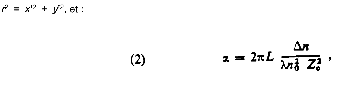
- (x, y). Le paramètre de Fresnel a s'écrit encore :
-

- définissant ainsi une longueur d'onde équivalente λeq:

- ou encore :

- définissant ainsi la distance focale fc de la lentille de Fresnel :

- λ: wavelength of the source,
- L: length of the crystal,
- n o: ordinary index of the crystal,
- An: absolute value of the difference between the ordinary and extraordinary indices, x, y, z: coordinates in the object volume,
- x ', y': coordinates in the hologram plane,
- where Z (x, y) is the distance between the holographic plane and the object point considered, located at the lateral position
- (x, y). The Fresnel parameter a is still written:
-
- thus defining an equivalent wavelength λ eq :
- or :
- thus defining the focal distance f c of the Fresnel lens:
Dans le cas ou l'objet considéré est plan (a = constante) la longueur d'onde équivalente et la focale fe sont des constantes du système.In the case where the object considered is plane (a = constant) the equivalent wavelength and the focal length f e are constants of the system.
La relation (4) montre alors que l'hologramme conoscopique d'un point enregistré à la longueur d'onde λ est similaire à l'hologramme de ce même point enregistré en lumière cohérente (holographie de Gabor) à la longueur d'onde équivalente λeq; notons que l'hologramme conoscopique mesure des intensités et non des amplitudes.The relation (4) then shows that the conoscopic hologram of a point recorded at the wavelength λ is similar to the hologram of this same point recorded in coherent light (Gabor holography) at the equivalent wavelength λ eq ; note that the conoscopic hologram measures intensities and not amplitudes.
Les distances Ze et L étant du même ordre de grandeur et An étant de l'ordre de 0,1, la longueur d'onde λeq est supérieure à la longueur d'onde réelle d'enregistrement λ; typiquement λeq = 3 à 100µm.The distances Z e and L being of the same order of magnitude and An being of the order of 0.1, the wavelength λ eq is greater than the actual recording wavelength λ; typically λ eq = 3 to 100µm.
Il s'en suit que la résolution latérale dans l'hologramme (proportionnelle à la longueur d'onde X ) est plus faible en holographie conoscopique qu'en holographie classique ; elle est de l'ordre de quelques dizaines de micromètres.It follows that the lateral resolution in the hologram (proportional to the wavelength X) is lower in conoscopic holography than in conventional holography; it is of the order of a few tens of micrometers.
Comme indiqué précédemment, l'hologramme enregistré avec un dispositif conoscopique contient toute l'information utile.As previously indicated, the hologram recorded with a conoscopic device contains all the useful information.
Par exemple pour l'hologramme d'un point correspondant à une zone de Fresnel :
- - le centre de la zone et le point objet sont sur la même droite, parallèle à l'axe optique, et si le point objet est translaté, transversalement ou latéralement, l'hologramme se translate indentiquement dans le plan holographique. Les coordonnées du centre C(xo, yo) de la zone de Fresnel sont donc égales, aux deux premières coordonnées du point P(xo, yo, zo) holographié.
- - l'intensité de l'hologramme donne l'énergie lumineuse dans le cône d'ouverture de lumière.
- - l'espacement des franges fournit la distance de l'objet au plan d'observation, indépendamment de la position du dispositif conoscopique. On peut en effet écrire :


- - the center of the area and the object point are on the same line, parallel to the optical axis, and if the object point is translated, transversely or laterally, the hologram translates identically in the holographic plane. The coordinates of the center C (x o , yo) of the Fresnel zone are therefore equal to the first two coordinates of the holographed point P (x o , y o , z o ).
- - the intensity of the hologram gives the light energy in the light-opening cone.
- - the fringe spacing provides the distance from the object to the observation plane, regardless of the position of the conoscopic device. We can indeed write:
Malgré les grands espoirs fondés sur l'holographie conoscopique précitée, celle-ci n'a pas connu jusqu'ici de développements industriels.Despite the great hopes based on the aforementioned conoscopic holography, this one has so far known no industrial developments.
Cela semble du au fait que l'hologramme ainsi obtenu s'avère en fait assez difficile à exploiter.This seems to be due to the fact that the hologram thus obtained turns out to be rather difficult to exploit.
Les inventeurs ont déterminé que l'hologramme conoscopique englobe en fait deux informations parasites correspondant respectivement au fond continu cohérent et à une image conjuguée qui brouillent l'information de base suffisante pour reconstruire l'objet.The inventors have determined that the conoscopic hologram in fact encompasses two parasitic information corresponding respectively to the coherent continuous background and to a conjugate image which blur sufficient basic information to reconstruct the object.
Ces deux informations parasites superposées à l'information utile lors de l'enregistrement d'un hologramme conoscopique peuvent être mises en évidence en éclairant l'hologramme conoscopique enregistré sur un film photosensible par une onde plane monochromatique. On observe alors en effet trois faisceaux diffractés : le premier représente l'onde directement transmise par le film et correspond au fond continu ; le second est une onde sphérique divergeant d'un objet virtuel qui est la réplique de l'objet original ; le troisième est une onde sphérique convergeant vers une image réelle conjuguée de l'objet située symétriquement à l'image virtuelle par rapport au plan de l'hologramme.These two parasitic information superimposed on the useful information during the recording of a conoscopic hologram can be highlighted by illuminating the conoscopic hologram recorded on a photosensitive film by a monochromatic plane wave. We then observe three diffracted beams: the first represents the wave directly transmitted by the film and corresponds to the continuous background; the second is a spherical wave diverging from a virtual object which is the replica of the original object; the third is a spherical wave converging towards a real image conjugated with the object located symmetrically with the virtual image compared to the plane of the hologram.
Les deux informations parasites précitées (fond continu et image conjuguée) peuvent également être mises en évidence par l'approche plus théorique suivante.The two aforementioned parasitic information (continuous background and combined image) can also be highlighted by the following more theoretical approach.
Dans le cas d'objets plans, la transformation linéaire entre l'intensité I(x, y) de l'objet et l'intensité H(x', y') dans l'hologramme est une convolution :![]()
![]()
Après développement de l'équation de convolution (10), l'hologramme apparaît comme une transformée de Fresnel :![]()


![]()
La présente invention a maintenant pour but de proposer des moyens permettant de supprimer le fond continu et l'image conjuguée de l'hologramme enregistré.The present invention now aims to provide means for eliminating the continuous background and the combined image of the recorded hologram.
Ce but est atteint selon l'invention grâce à un procédé de reconstruction d'une image d'un objet sans images parasites avec génération d'un hologramme, en lumière incohérente, comprenant les étapes consistant à :
- - i) enregistrer à travers un système conoscopique comprenant un cristal biréfringent inséré entre deux polariseurs circulaires, plusieurs différents hologrammes conoscopiques d'un même objet, sans déplacement relatif de celui-ci, selon différentes configurations de polarisation respectives, du système conoscopique, et numériser la pluralité de différents hologrammes afin de former une pluralité de signaux numériques, chacun correspondant à un des hologrammes conoscopique,
- - ii) reconstruire numériquement une image de l'objet, la reconstruction incluant la combinaison de ces signaux d'une telle manière que les informations correspondant au fond continu et à l'image conjuguée sont supprimées dans l'image reconstruite.
- - i) record through a conoscopic system comprising a birefringent crystal inserted between two circular polarizers, several different conoscopic holograms of the same object, without relative displacement of the latter, according to different respective polarization configurations, of the conoscopic system, and digitize the plurality of different holograms in order to form a plurality of digital signals, each corresponding to one of the conoscopic holograms,
- ii) digitally reconstructing an image of the object, the reconstruction including the combination of these signals in such a way that the information corresponding to the continuous background and to the conjugate image is deleted in the reconstructed image.
Selon une autre caractéristique avantageuse de la présente invention, les polariseurs circulaires sont formés d'un polariseur linéaire et d'une lame quart d'onde susceptibles de rotation relative, et coupés à des moyens d'entraînement en rotation, et les différentes configurations de polarisation sont obtenues successivement par rotation du polariseur linéaire et/ou de la lame quart d'onde grâce aux moyens d'entraînement.According to another advantageous characteristic of the present invention, the circular polarizers are formed of a linear polarizer and a quarter-wave plate capable of relative rotation, and cut to rotation drive means, and the different configurations of polarization are obtained successively by rotation of the linear polarizer and / or of the quarter-wave plate thanks to the drive means.
La présente invention concerne également un dispositif pour la mise en oeuvre du procédé précité du type comprenant un système conoscopique comportant un cristal biréfringent inséré entre deux polariseurs circulaires, caractérisé par le fait qu'il comprend :
- - des moyens permettant d'enregistrer à l'aide dudit système conoscopique, différents hologrammes conoscopiques d'un même objet, sans déplacement relatif de celui-ci, selon différentes configurations de polarisations respectives du système conoscopique, et des moyens permettant de numériser la pluralité de différents hologrammes, afin de former une pluralité de signaux numériques, chacun correspondant à un des hologrammes conoscopiques, et
- - des moyens aptes à reconstruire numériquement une image de l'objet, la reconstruction incluant la combinaison de ces signaux d'une telle manière que les informations correspondant au fond continu et à l'image conjuguée sont supprimées dans l'image reconstruite.
- means for recording, using said conoscopic system, different conoscopic holograms of the same object, without relative displacement of the latter, according to different configurations of respective polarizations of the conoscopic system, and means for digitizing the plurality different holograms, in order to form a plurality of digital signals, each corresponding to one of the conoscopic holograms, and
- - Means capable of digitally reconstructing an image of the object, the reconstruction including the combination of these signals in such a way that the information corresponding to the continuous background and to the conjugate image is deleted in the reconstructed image.
D'autres caractéristiques, buts et avantages de la présente invention apparaîtront à la lecture de la description détaillée qui va suivre et en regard des dessins annexés, donnés à titre d'exemples non limitatifs et sur lesquels, les figures 1 et 2 annexées qui illustrent l'état de la technique ayant déjà été décrites :
- - la figure 3 représente le schéma général d'un dispositif conoscopique permettant de mettre en oeuvre la présente invention,
- - la figure 4 illustre schématiquement un mode de réalisation préférentiel de moyens polariseurs proposés dans le cadre de la présente invention,
- - la figure 5 représente un tableau d'exemples de configurations de polarisations obtenues avec les moyens polariseurs précités conformes à la présente invention,
- - la figure 6 représente schématiquement un mode de réalisation du dispositif conforme à la présente invention,
- - la figure 7A représente une vue schématique générale de moyens polariseurs conforme à un autre mode de réalisation de la présente invention, et
- - la figure 7B représente une vue de détail de ces moyens.
- FIG. 3 represents the general diagram of a conoscopic device making it possible to implement the present invention,
- FIG. 4 schematically illustrates a preferred embodiment of polarizing means proposed in the context of the present invention,
- FIG. 5 represents a table of examples of polarization configurations obtained with the aforementioned polarizing means in accordance with the present invention,
- FIG. 6 schematically represents an embodiment of the device according to the present invention,
- FIG. 7A represents a general schematic view of polarizing means according to another embodiment of the present invention, and
- - Figure 7B shows a detailed view of these means.
On aperçoit sur la figure 3 annexée un dispositif holographique conforme à la présente invention qui comprend pour l'essentiel : un conoscope, des moyens d'enregistrement et de numérisation 50, des moyens de traitement 60 et des moyens d'exploitation 70.A holographic device according to the present invention can be seen in the appended FIG. 3 which essentially comprises: a conoscope, recording and digitizing means 50, processing means 60 and operating means 70.
Le conoscope comprend un cristal biréfringent 30 inséré entre deux polariseurs 10, 20. Le conoscope comprend en outre des moyens 40 permettant de contrôler la polarisation.The conoscope comprises a
Les moyens 50 sont conçus, en combinaison avec les moyens de contrôle 40, pour enregistrer et numériser différents hologrammes conoscopiques d'un même objet, sans déplacement relatif de celui-ci, sous différentes configurations de polarisation respectives. Les moyens 50 peuvent être formés d'une caméra CCD à transfert de charge.The means 50 are designed, in combination with the control means 40, to record and digitize different conoscopic holograms of the same object, without relative displacement of the latter, under different respective polarization configurations. The means 50 can be formed of a CCD camera with charge transfer.
Les moyens 60 sont conçus pour éliminer le fond continu et l'image conjuguée de l'hologramme enregistré et numérisé dans les moyens 50.The means 60 are designed to eliminate the continuous background and the combined image of the hologram recorded and digitized in the
Les moyens 70 sont de préférence conçus pour reconstruire l'hologramme résultant et visualiser l'image correspondante. Les moyens 70 peuvent être utilisés à d'autres fins.The means 70 are preferably designed to reconstruct the resulting hologram and display the corresponding image. The means 70 can be used for other purposes.
Le système conoscopique décrit dans le document US-A-4 602 844 comprend des polariseurs circulaires d'entrée et de sortie, qui sont constitués d'un polariseur rectiligne et d'une lame quart d'onde solidaire du polariseur rectiligne.The conoscopic system described in document US-A-4 602 844 comprises circular input and output polarizers, which consist of a rectilinear polarizer and a quarter-wave plate integral with the rectilinear polarizer.
Dans le cadre du mode de réalisation, considéré actuellement comme préférentiel, de la présente invention, le polariseur rectiligne et la lame quart d'onde sont désolidarisés.In the context of the embodiment, currently considered preferential, of the present invention, the rectilinear polarizer and the quarter-wave plate are separated.
Cela permet d'imposer, par rotation de la lame quart d'onde, n'importe quelle polarisation à l'onde transmise.This makes it possible to impose, by rotation of the quarter-wave plate, any polarization on the transmitted wave.
On aperçoit ainsi sur la figure 4 annexée, un ensemble polariseur d'entrée 10 qui comprend un polariseur linéaire 12 et une lame quart d'onde 14 ; un ensemble polariseur de sortie 20 qui comprend un polariseur linéaire 22 et une lame quart d'onde 24 ; un cristal biréfringent 30, intercalé entre les deux ensembles 10, 20 et un plan d'observation 50 situé en aval de l'ensemble polariseur de sortie par rapport à l'objet à examiner.We thus see in Figure 4 attached, an
Le polariseur linéaire 12 et la lame quart d'onde 14 s'étendent perpendiculairement à l'axe Z. Ils sont non solidaires entre eux et donc susceptibles de rotation relative autour de l'axe Z.The
De même le polariseur linéaire 12 et la lame quart d'onde 24 s'étendent perpendiculairement à l'axe Z. Ils sont non solidaires entre eux et donc susceptibles de rotation relative autour de l'axe Z par rapport au polariseur linéaire 12 et la lame quart d'onde 14 composant l'ensemble polariseur d'entrée.Similarly, the
La rotation des éléments précités est assurée par des moteurs intégrés aux moyens de contrôle 40.The above-mentioned elements are rotated by motors integrated into the control means 40.
Comme indiqué précédemment, le plan d'observation 50 est de préférence matérialisé par un système de prise de vue, par exemple une caméra CCD à transfert de charge.As indicated above, the
Les angles φo, φ1, φ2, φ3, repèrent la position des axes principaux de polarisation des diverses lames 12, 14, 22, 24, par rapport à un plan principal arbitraire passant par l'axe Z. Selon la figure 4 annexée, ce plan principal est défini par les axes Z et X. L'onde incidente 9 se transforme en l'onde 8' à l'intérieur du cristal 30. Les vecteurs électriques des ondes extraordinaire et ordinaire associées sont D et o.The angles φ o , φ 1 , φ 2 , φ 3 , identify the position of the main axes of polarization of the
L'angle représente l'inclinaison, par rapport au plan principal, du plan défini par l'axe Z et le vecteur d'onde S incidente.The angle represents the inclination, relative to the main plane, of the plane defined by the Z axis and the incident S wave vector.
On appelle ai la différence φo- φ1 et a2 la différence 4)2 - φ3.We call ai the difference φ o - φ 1 and a 2 the difference 4) 2 - φ 3 .
Par rotation d'une lame quart d'onde de π/2 un polariseur circulaire droit devient gauche ou inversement.By rotation of a quarter wave plate of π / 2 a right circular polarizer becomes left or vice versa.
Par rotation d'une lame quart d'onde de π/4 un polariseur circulaire devient rectiligne.By rotation of a quarter wave plate of π / 4 a circular polarizer becomes rectilinear.
Dans le premier cas, le déphasage supplémentaire introduit entre les deux ondes ordinaire et extraordinaire est de π. La fonction de transfert du système conoscopique sera du type 1 + cos(Δφ + π) soit 1 - cos(Δφ).In the first case, the additional phase shift introduced between the ordinary and extraordinary waves is π. The transfer function of the conoscopic system will be of the
Dans le second cas où la polarisation de l'onde incidente sur le cristal est linéaire, le déphasage introduit est de 7r/2 et la fonction de transfert sera du type cos(Δφ + 7r/2) soit sin(Δφ).In the second case where the polarization of the incident wave on the crystal is linear, the phase shift introduced is 7 r / 2 and the transfer function will be of the cos type (Δφ + 7 r / 2) or sin (Δφ).
Les arguments quailitatifs développés ci-dessus démontrent que par rotation de la lame quart d'onde 14 à l'entrée du système (ou le cas échéant de la lame quart d'onde 24) il est possible d'engendrer les deux réponses percussionnelles fondamentales à savoir cos(Δφ) et sin(Δφ).The quailitative arguments developed above demonstrate that by rotation of the quarter-
La combinaison de ces réponses percussionnelles permet d'éliminer l'image conjuguée.The combination of these percussive responses eliminates the combined image.
On va maintenant préciser les modalités précises d'un mode de mise en oeuvre préférentiel de l'invention.We will now specify the precise modalities of a preferred embodiment of the invention.
Quatre prises de vue, successives sont effectuées après rotation appropriée des éléments composant les ensembles polariseurs.Four successive shots are taken after appropriate rotation of the elements making up the polarizer assemblies.
Pour la première prise de vue, les polariseurs d'entrée et de sortie sont circulaires :![]()
![]()
![]()
![]()
Pour la seconde prise de vue, les polariseurs d'entrée et de sortie sont également circulaires, mais croisés![]()
![]()
La réponse percussionnelle s'écrit :![]()
![]()
Pour la troisième prise de vue le polariseur d'entrée est rectiligne :![]()
![]()
La réponse percussionnelle s'écrit :![]()
![]()
Pour la quatrième prise de vue, le polariseur d'entrée est encore rectiligne mais![]()
![]()
La réponse percussionnelle s'écrit :![]()
![]()
Les fonctions de transfert obtenues dans les quatre cas précités sont rappelées dans le tableau de la figure 5 annexée.The transfer functions obtained in the four aforementioned cases are recalled in the table in FIG. 5 appended.
On remarquera que la troisième fonction s'obtient aussi bien par a2 = -π/4 que par ai = 0 à la condition de changer φ0 en φ0 - 7r/2. Ainsi les quatre fonctions de transfert s'obtiennent elles par simple ajustement des lames d'entrée (ou des lames de sortie).It will be noted that the third function is obtained as well by a 2 = -π / 4 as by ai = 0 on the condition of changing φ 0 to φ 0 - 7 r / 2. Thus the four transfer functions are obtained by simple adjustment of the input blades (or output blades).
Pratiquement, la rotation des axes principaux de polarisation des diverses lames peut être réalisée mécaniquement si celles-ci sont des lames cristallines ou électriquement si celles-ci sont des valves électro-optiques, telles que les valves commercialisées par la société DISPLAYTECH INC sous la référence LV 500A.In practice, the main axes of polarization of the various blades can be rotated mechanically if they are crystalline blades or electrically if these are valves electro-optics, such as the valves sold by the company DISPLAYTECH INC under the reference LV 500A.
Il est ensuite possible, à partir de combinaisons linéaires simples des fonctions de transfert du tableau précédent d'obtenir les deux fonctions de transfert suivantes :![]()
![]()
![]()
![]()
![]()
![]()
![]()
![]()
![]()
![]()
Si l'on appelle et les variables correspondant à et dans le domaine spectral les transformées de Fourier de chacune des fonctions de transfert s'écrit :![]()


![]()
Par conséquent, si l'on considère la combinaison linéaire suivante :![]()

![]()
Le problème qui se pose alors est d'éliminer T4. D'après sa forme analytique T4 n'est significative qu'autour de p = 0. Par conséquent si l'on veut effectuer cette correction pour βρ2 « 1 on peut faire l'hypothèse que le paramètre β ne varie pas d'une manière significative sur l'épaisseur de l'objet (ce qui est le cas si l'on utilise une optique standard classique qui aura tendance à comprimer l'épaisseur en z de l'objet) et diffère peu de β0 correspondant au plan moyen de l'objet. On peut alors approximer T par (j/π)-βo autour de 0 et retrancher cette valeur dans le plan de Fourier. Pour des valeurs de βρ2 plus élevées, on peut approximer au deuxième ordre T4 par jo/(βoρ2).The problem which then arises is to eliminate T 4 . According to its analytical form T 4 is only significant around p = 0. Consequently if we want to make this correction for βρ 2 "1 we can assume that the parameter β does not vary from significantly on the thickness of the object (which is the case if we use a standard standard optic which will tend to compress the thickness in z of the object) and differs little from β 0 corresponding to the plane medium of the object. We can then approximate T by (j / π) -βo around 0 and subtract this value from the Fourier plane. For higher values of βρ 2 , we can approximate to the second order T 4 by jo / (βoρ 2 ).
Ces traitements ayant été effectués, on peut considérer, avec une très bonne approximation, que la fonction de transfert du système est idéale (entre autres l'hologramme sera reconstruit sans les artefacts dus à l'image conjuguée) et s'écrit :![]()
![]()
En posant le problème en coordonnées cartésiennes, l'hologramme conoscopique enregistré, s'écrira donc :![]()
![]()
![]()
![]()
En posant a (x,y) = ao + ai (x, y) et en développant l'exponentielle autour de ao on obtient
On peut écrire cela sous forme d'une série de convolution :

![]()
![]()
On voit que le problème de reconstruction numérique se ramène alors à un problème de déconvolution.We see that the problem of digital reconstruction is reduced to a problem of deconvolution.
On a illustré schématiquement sur la figure 6 annexée, un mode de réalisation particulier de la présente invention.Illustrated schematically in Figure 6 attached, a particular embodiment of the present invention.
La scène S est éclairée par une lame monochromatique à vapeur de sodium 90 et imagée à l'aide d'une optique 80 d'ouverture suffisamment grande pour obtenir la résolution latérale voulue. L'optique d'entrée 80 peut aller du microscope au zoom.Scene S is lit by a monochromatic
L'un au moins des polariseurs circulaires d'entrée ou de sortie 10, 20, est constitué d'un polariseur rectiligne 12, 22, et d'une lame quart d'onde 14, 24, désolidarisées et susceptibles de rotation 29 relative grâce à des moteurs électriques respectivement associés.At least one of the input or
La rotation des axes optiques de polarisation des éléments 12, 14, 22, 24, intégrés au conoscope est effectuée mécaniquement ; cette solution mécanique permet de bénéficier d'éléments optiques de très haute qualité.The rotation of the optical axes of polarization of the
Le cristal 30 est un cylindre de calcite de longueur 35 mm et de diamètre 20 mm. (La résolution dans l'hologramme est modifiable en fonction des caractéristiques géométriques du système, soit la longueur et la biréfringence du cristal).The
Les moyens d'enregistrement 50 sont formés d'une caméra à transfert de charge CCD de 512 x 512 pixels, avec une résolution de 10µrn, sur une dynamique de 255 niveaux de gris (soit un codage sur 8 bits). Les hologrammes sont ainsi saisis directement et numérisés par la caméra CCD.The recording means 50 are formed by a CCD charge transfer camera of 512 x 512 pixels, with a resolution of 10 μrn, on a dynamic of 255 gray levels (ie an 8-bit coding). The holograms are thus captured directly and digitized by the CCD camera.
Les moyens de traitement 60 sont formés d'un microordinateur, équipé de cartes de traitement du signal et d'un coprocesseur arithmétique. Ces moyens 60 reçoivent les signaux numérisés issus de la caméra CCD 50. Ils pilotent les moteurs qui assurent l'entraînement des éléments 12, 14, 22, 24 intégrés au conoscope. Les moyens 60 possèdent dans leur mémoire, après traitement du signal, l'information en intensité et en profondeur nécessaire pour réaliser pratiquement en temps réel les reconstructions numériques permettant l'obtention de l'équation de la surface ou des déformations.The processing means 60 are formed by a microcomputer, equipped with signal processing cards and an arithmetic coprocessor. These means 60 receive the digital signals from the
On notera que pour améliorer la fiabilité du système, le traitement peut être opéré sur une sommation de N images.Note that to improve the reliability of the system, the processing can be carried out on a summation of N images.
Pour donner un ordre de grandeur, les cartes actuelles de numérisation d'images peuvent effectuer la numérisation et la sommation de 128 images 512 par 512 en 4s.To give an order of magnitude, the current image digitization cards can perform the digitization and the summation of 128 images 512 by 512 in 4s.
Le signal correspondant à la reconstruction numérique issu des moyens 60 peut être appliqué à un écran vidéo 70 classique.The signal corresponding to the digital reconstruction from the
Différentes voies sont envisageables pour reconstruire numériquement une image des objets à l'aide de l'hologramme enregistré.Different ways can be envisaged to digitally reconstruct an image of the objects using the recorded hologram.
On distinguera la reconstruction numérique d'objets plans, de la reconstruction numérique d'objets tridimensionnels.A distinction will be made between digital reconstruction of planar objects and digital reconstruction of three-dimensional objects.
Dans le cas d'objets plans, trois méthodes de reconstruction numérique d'objet sont envisagées.In the case of planar objects, three methods of digital object reconstruction are envisaged.
La première méthode de reconstruction numérique d'objets plans correspond à une simulation numérique de la reconstruction optique cohérente. On a en effet indiqué dans le document US-A-4 602 844, en regard de sa figure 5 que l'image d'un objet pouvait être obtenue en éclairant un film photographique sur lequel est enregistré un hologramme conoscopique, à l'aide d'une lumière cohérente.The first method of digital reconstruction of planar objects corresponds to a digital simulation of coherent optical reconstruction. It has indeed been indicated in document US-A-4 602 844, with reference to its FIG. 5, that the image of an object could be obtained by illuminating a photographic film on which a conoscopic hologram is recorded, using of coherent light.
Une transformée de Fresnel se ramène à une transformée de Fourier en vertu de la relation :![]()
![]()
Après multiplication de l'hologramme par un terme de phase convenable, l'objet peut donc être reconstruit par simple transformée de Fourier. Numériquement cette opération se réalise simplement par utilisation des algorithmes de transformée de Fourier rapide. Pour obtenir un accord satisfaisant entre le calcul numérique de la transformée de Fourier et la transformée de Fourier obtenue analytiquement, il suffit de choisir correctement le pas d'échantillonnage dans l'hologramme.After multiplying the hologram by a suitable phase term, the object can therefore be reconstructed by simple Fourier transform. Numerically this operation is carried out simply by using fast Fourier transform algorithms. To obtain a satisfactory agreement between the numerical computation of the Fourier transform and the Fourier transform obtained analytically, it suffices to correctly choose the sampling step in the hologram.
La seconde méthode de reconstruction numérique d'objets plans correspond à une simulation numeri- que de la construction optique conoscopique.The second method of digital reconstruction of planar objects corresponds to a digital simulation of the conoscopic optical construction.
On a en effet montré dans le document US-A-4 602 844, en regard de sa figure 4, que l'image peut être obtenue en plaçant l'hologramme conoscopique à l'entrée du système d'enregistrement. Numériquement cela est traduit par la convolution de l'hologramme avec la fonction de Fresnel cos(ur2).It has indeed been shown in document US-A-4 602 844, with reference to its FIG. 4, that the image can be obtained by placing the conoscopic hologram at the input of the recording system. Numerically this is translated by the convolution of the hologram with the Fresnel function cos (ur 2 ).
La troisième méthode de reconstruction numérique d'objets plans correspond à un filtrage de Wiener. Cette méthode est mise en oeuvre en traitant la transformée de Fourier de l'hologramme, par un filtre adapté, dans le domaine de Fourier.The third method of digital reconstruction of planar objects corresponds to Wiener filtering. This method is implemented by processing the Fourier transform of the hologram, by a suitable filter, in the Fourier domain.
Dans le cas de la reconstruction numérique d'objets tridimensionnels, la transformation linéaire n'est plus une convolution, elle s'écrit :![]()
![]()
Dans le cas d'objet de faible extension longitudinale, c'est-à-dire :


Il est alors possible de déterminer une première approximation des fonctions a(x,y) et 1(x,y) réelles, en ne conservant que les deux premiers termes dans le développement en série. A l'ordre suivant les premières approximations de 1 et a permettent de calculer les termes suivant dans le développement. Ceux-ci sont alors soustraits à l'hologramme de départ et on résout une nouvelle fois l'équation au second ordre.It is then possible to determine a first approximation of the real functions a (x, y) and 1 (x, y), keeping only the first two terms in the series development. In the order following the first approximations of 1 and a allow to calculate the following terms in the development. These are then subtracted from the starting hologram and the second order equation is again solved.
Bien entendu la présente invention n'est pas limitée au mode de réalisation préférentiel qui vient d'être décrit mais s'étend à toutes variantes conformes à son esprit.Of course the present invention is not limited to the preferred embodiment which has just been described but extends to all variants in accordance with its spirit.
Selon une première variante, les éléments 12, 14 et 22, 24 composant le polariseur d'entrée 10 et le polariseur de sortie 20 sont fixes et non point susceptibles de rotation relative, et les différents polarisations requises pour obtenir plusieurs hologrammes répondant à des fonctions de transfert différentes, telles que celles indiquées sur le tableau de la figure 5, sont obtenues par insertion d'éléments polariseurs appropriés en amont et/ou en aval du cristal biréfringent 30.According to a first variant, the
Selon une seconde variante, le système conforme à la présente invention n'enregistre pas successivement 4 hologrammes conoscopiques correspondant respectivement à des polarisations différentes, mais enregistre simultanément 4 hologrammes correspondant à des polarisations différentes appropriées. Pour cela, l'un des polariseurs, de préférence le polarisateur de sortie 20 adjacent aux moyens d'enregistrement 50 est formé d'un réseau de P lignes Q colonnes de matrices 25, soit PQ matrices formées chacune de 4 sous-éléments 26, 27, 28, 29 correspondant respectivement aux polarisations requises. De préférence, chacune des PQ matrices 25 est réalisée sous forme d'une matrice à 2 lignes et 2 colonnes de sous éléments, comme illustré schématiquement sur la figure 7 annexée. Chacun des sous éléments 26, 27, 28, 29 correspond en surface à un pixel des moyens d'enregistrement 50.According to a second variant, the system according to the present invention does not successively record 4 conoscopic holograms corresponding respectively to different polarizations, but simultaneously records 4 holograms corresponding to different suitable polarizations. For this, one of the polarizers, preferably the
La présente invention peut donner lieu à de nombreuses applications ; on citera à titre d'exemple non limitatif : le domaine de l'inspection automatique de pièces, de la reconnaissance d'objets et de la robotique, de l'interféromètrie holographique, et l'imagerie tridimensionnelle.The present invention can give rise to numerous applications; By way of non-limiting example, mention may be made of the field of automatic inspection of parts, recognition of objects and robotics, holographic interferometry, and three-dimensional imaging.
On notera par ailleurs que l'enregistrement des hologrammes conoscopiques, leur traitement pour éliminer le fond continu et l'image conjuguée, et la reconstruction pour exploitation peuvent être réalisés en diverses étapes séparées dans le temps.It will also be noted that the recording of the conoscopic holograms, their processing to eliminate the continuous background and the conjugate image, and the reconstruction for exploitation can be carried out in various stages separated in time.
Claims (16)

Priority Applications (1)
| Application Number | Priority Date | Filing Date | Title |
|---|---|---|---|
| AT89403649T ATE101290T1 (en) | 1988-12-27 | 1989-12-26 | METHOD AND DEVICE FOR HOLOGRAPHY WITH INCOHERENT LIGHT. |
Applications Claiming Priority (2)
| Application Number | Priority Date | Filing Date | Title |
|---|---|---|---|
| FR8817225 | 1988-12-27 | ||
| FR8817225A FR2641091B1 (en) | 1988-12-27 | 1988-12-27 |
Publications (2)
| Publication Number | Publication Date |
|---|---|
| EP0376837A1 EP0376837A1 (en) | 1990-07-04 |
| EP0376837B1 true EP0376837B1 (en) | 1994-02-02 |
Family
ID=9373454
Family Applications (1)
| Application Number | Title | Priority Date | Filing Date |
|---|---|---|---|
| EP89403649A Expired - Lifetime EP0376837B1 (en) | 1988-12-27 | 1989-12-26 | Method and apparatus for holography using incoherent light |
Country Status (7)
| Country | Link |
|---|---|
| US (1) | US4976504A (en) |
| EP (1) | EP0376837B1 (en) |
| JP (1) | JP3155262B2 (en) |
| AT (1) | ATE101290T1 (en) |
| CA (1) | CA2006606C (en) |
| DE (2) | DE68912918D1 (en) |
| FR (1) | FR2641091B1 (en) |
Families Citing this family (11)
| Publication number | Priority date | Publication date | Assignee | Title |
|---|---|---|---|---|
| FR2646252B1 (en) * | 1989-04-21 | 1991-12-13 | France Etat | PROCESS AND DEVICE HOLOGRAPHIC IN INCOHERENT LIGHT FOR THE STUDY OF TERRESTRIAL RELIEF |
| FR2646251B1 (en) * | 1989-04-21 | 1991-08-09 | France Etat | IMPROVED HOLOGRAPHIC DEVICE IN INCOHERENT LIGHT |
| FR2665270B1 (en) * | 1990-07-27 | 1994-05-13 | Etat Francais Cnet | LIGHT SPACE MODULATOR DEVICE AND HIGH DYNAMIC CONOSCOPIC HOLOGRAPHY SYSTEM COMPRISING SUCH A MODULATOR DEVICE. |
| FR2684202B1 (en) * | 1991-11-27 | 1994-03-04 | Conoscope Sa | IMPROVED HOLOGRAPHIC METHOD AND DEVICE IN INCOHERENT LIGHT. |
| FR2730571B1 (en) * | 1995-02-10 | 1997-04-04 | Controle Dimensionnel Optique | METHOD AND DEVICE FOR MEASURING THE DISTRIBUTION OF THE MOBILITY OF PARTICULAR ELEMENTS IN A MEDIUM |
| RU2095762C1 (en) * | 1995-05-16 | 1997-11-10 | Евсей Исаакович Якубович | Method for recording and displaying of three- dimensional picture of object and device for recording and displaying of three-dimensional picture of object |
| US5953137A (en) * | 1996-10-09 | 1999-09-14 | Optimet, Optical Metrology Ltd. | Linear conoscopic holography |
| WO2008014461A2 (en) | 2006-07-28 | 2008-01-31 | Optimet, Optical Metrology Ltd. | Double-sided measurement of dental objects using an optical scanner |
| JP5414523B2 (en) * | 2006-10-20 | 2014-02-12 | バイオアキシアル エスエーエス | Optical device based on internal cone diffraction |
| CN101801307A (en) * | 2007-09-13 | 2010-08-11 | 爱德芳世株式会社 | Dental inlay graft measuring/machining system |
| WO2009113068A1 (en) | 2008-03-12 | 2009-09-17 | Optimet, Optical Metrology Ltd. | Intraoral imaging system and method based on conoscopic holography |
Family Cites Families (4)
| Publication number | Priority date | Publication date | Assignee | Title |
|---|---|---|---|---|
| US3536371A (en) * | 1967-07-20 | 1970-10-27 | Daniel Post | Method and means for producing and utilizing arrays of diffraction type lenses for micro-electronics mask making |
| FR2143552B1 (en) * | 1971-06-29 | 1974-03-22 | Thomson Csf | |
| US4036552A (en) * | 1975-02-10 | 1977-07-19 | Minnesota Mining And Manufacturing Company | Retroreflective material made by recording a plurality of light interference fringe patterns |
| US4602844A (en) * | 1984-10-01 | 1986-07-29 | California Institute Of Technology | Monochromatic incoherent light holography |
-
1988
- 1988-12-27 FR FR8817225A patent/FR2641091B1/fr not_active Expired - Lifetime
-
1989
- 1989-12-22 CA CA002006606A patent/CA2006606C/en not_active Expired - Fee Related
- 1989-12-22 US US07/455,988 patent/US4976504A/en not_active Expired - Lifetime
- 1989-12-26 EP EP89403649A patent/EP0376837B1/en not_active Expired - Lifetime
- 1989-12-26 DE DE89403649A patent/DE68912918D1/en not_active Expired - Lifetime
- 1989-12-26 DE DE68912918T patent/DE68912918T4/en not_active Expired - Lifetime
- 1989-12-26 AT AT89403649T patent/ATE101290T1/en not_active IP Right Cessation
- 1989-12-27 JP JP33986689A patent/JP3155262B2/en not_active Expired - Lifetime
Also Published As
| Publication number | Publication date |
|---|---|
| DE68912918D1 (en) | 1994-03-17 |
| ATE101290T1 (en) | 1994-02-15 |
| FR2641091B1 (en) | 1991-04-19 |
| DE68912918T4 (en) | 1994-09-08 |
| CA2006606C (en) | 1994-12-06 |
| FR2641091A1 (en) | 1990-06-29 |
| JP3155262B2 (en) | 2001-04-09 |
| EP0376837A1 (en) | 1990-07-04 |
| DE68912918T2 (en) | 1994-06-23 |
| JPH02264286A (en) | 1990-10-29 |
| CA2006606A1 (en) | 1990-06-27 |
| US4976504A (en) | 1990-12-11 |
Similar Documents
| Publication | Publication Date | Title |
|---|---|---|
| EP0256051B1 (en) | Image processing device for controlling the transfer function of an optical system | |
| EP0394137B1 (en) | Apparatus for incoherent light holography | |
| EP1071974B1 (en) | Microscope generating a three-dimensional representation of an object and images generated by such a microscope | |
| WO1998013715A1 (en) | Microscope generating a three-dimensional representation of an object | |
| Stoykova et al. | Twin-image problem in digital holography-a survey | |
| EP0376837B1 (en) | Method and apparatus for holography using incoherent light | |
| US20040021871A1 (en) | Holographic imaging spectrometer | |
| EP2915009B1 (en) | Auto-referenced holographic imaging system | |
| CN107991242B (en) | Method and system for measuring polarization state of sample based on polarization splitting prism | |
| WO2002040937A1 (en) | Method and device for high-speed interferential microscopic imaging of an object | |
| EP1524491A1 (en) | Apparatus coupling an interferometer and a microscope | |
| EP0028548A1 (en) | Real-time optical correlation system | |
| FR2552895A1 (en) | MICROSCOPE FOR OBTAINING HIGH-RESOLUTION IMAGES WITHOUT OPTICAL PRECISION | |
| EP1043632A1 (en) | Device for digital holography | |
| EP3994529A1 (en) | Calibration-free phase shifting procedure for self-interference holography | |
| FR2730571A1 (en) | METHOD AND DEVICE FOR MEASURING THE DISTRIBUTION OF THE MOBILITY OF PARTICULAR ELEMENTS IN A MEDIUM | |
| FR2645976A1 (en) | ELECTRONIC HOLOGRAPHY APPARATUS | |
| US20220163918A1 (en) | Device and method for calibration-free phase shifting procedure for self-interference holography | |
| Agour et al. | Experimental investigation of holographic 3D-TV approach | |
| EP0394138B1 (en) | Method and apparatus for defining terrestrial profiles by use of incoherent light holography | |
| KR101498474B1 (en) | Resolution Improvement Method for Digital Holography via Multi-Step Interpolation | |
| Liu et al. | Advanced subsea imaging technique of digital holography: in situ measurement of marine microscale plankton and particles | |
| JP2023124051A (en) | Incoherent digital hologram signal processing device and imaging display system | |
| KR20230039251A (en) | How to improve digital holographic microscope image quality | |
| FR3125893A1 (en) | Lighting system, in particular for use in microscopy |
Legal Events
| Date | Code | Title | Description |
|---|---|---|---|
| PUAI | Public reference made under article 153(3) epc to a published international application that has entered the european phase |
Free format text: ORIGINAL CODE: 0009012 |
|
| AK | Designated contracting states |
Kind code of ref document: A1 Designated state(s): AT BE CH DE ES GB GR IT LI LU NL SE |
|
| 17P | Request for examination filed |
Effective date: 19900827 |
|
| 17Q | First examination report despatched |
Effective date: 19920909 |
|
| RAP1 | Party data changed (applicant data changed or rights of an application transferred) |
Owner name: FRANCE TELECOM |
|
| GRAA | (expected) grant |
Free format text: ORIGINAL CODE: 0009210 |
|
| AK | Designated contracting states |
Kind code of ref document: B1 Designated state(s): AT BE CH DE ES GB GR IT LI LU NL SE |
|
| PG25 | Lapsed in a contracting state [announced via postgrant information from national office to epo] |
Ref country code: IT Free format text: LAPSE BECAUSE OF FAILURE TO SUBMIT A TRANSLATION OF THE DESCRIPTION OR TO PAY THE FEE WITHIN THE PRE;WARNING: LAPSES OF ITALIAN PATENTS WITH EFFECTIVE DATE BEFORE 2007 MAY HAVE OCCURRED AT ANY TIME BEFORE 2007. THE CORRECT EFFECTIVE DATE MAY BE DIFFERENT FROM THE ONE RECORDED.SCRIBED TIME-LIMIT Effective date: 19940202 Ref country code: AT Effective date: 19940202 Ref country code: NL Effective date: 19940202 Ref country code: SE Effective date: 19940202 Ref country code: GR Free format text: LAPSE BECAUSE OF FAILURE TO SUBMIT A TRANSLATION OF THE DESCRIPTION OR TO PAY THE FEE WITHIN THE PRESCRIBED TIME-LIMIT Effective date: 19940202 Ref country code: ES Free format text: THE PATENT HAS BEEN ANNULLED BY A DECISION OF A NATIONAL AUTHORITY Effective date: 19940202 |
|
| REF | Corresponds to: |
Ref document number: 101290 Country of ref document: AT Date of ref document: 19940215 Kind code of ref document: T |
|
| GBT | Gb: translation of ep patent filed (gb section 77(6)(a)/1977) |
Effective date: 19940202 |
|
| REF | Corresponds to: |
Ref document number: 68912918 Country of ref document: DE Date of ref document: 19940317 |
|
| NLV1 | Nl: lapsed or annulled due to failure to fulfill the requirements of art. 29p and 29m of the patents act | ||
| PLBE | No opposition filed within time limit |
Free format text: ORIGINAL CODE: 0009261 |
|
| STAA | Information on the status of an ep patent application or granted ep patent |
Free format text: STATUS: NO OPPOSITION FILED WITHIN TIME LIMIT |
|
| PG25 | Lapsed in a contracting state [announced via postgrant information from national office to epo] |
Ref country code: BE Effective date: 19941231 Ref country code: CH Effective date: 19941231 Ref country code: LU Free format text: LAPSE BECAUSE OF NON-PAYMENT OF DUE FEES Effective date: 19941231 Ref country code: LI Effective date: 19941231 |
|
| 26N | No opposition filed | ||
| BERE | Be: lapsed |
Owner name: FRANCE TELECOM Effective date: 19941231 |
|
| REG | Reference to a national code |
Ref country code: CH Ref legal event code: PL |
|
| REG | Reference to a national code |
Ref country code: GB Ref legal event code: 732E |
|
| REG | Reference to a national code |
Ref country code: GB Ref legal event code: IF02 |
|
| PGFP | Annual fee paid to national office [announced via postgrant information from national office to epo] |
Ref country code: GB Payment date: 20050118 Year of fee payment: 16 |
|
| PG25 | Lapsed in a contracting state [announced via postgrant information from national office to epo] |
Ref country code: GB Free format text: LAPSE BECAUSE OF NON-PAYMENT OF DUE FEES Effective date: 20051226 |
|
| GBPC | Gb: european patent ceased through non-payment of renewal fee |
Effective date: 20051226 |
|
| PGFP | Annual fee paid to national office [announced via postgrant information from national office to epo] |
Ref country code: DE Payment date: 20090112 Year of fee payment: 20 |