EP0376409A2 - Time switch - Google Patents
Time switch Download PDFInfo
- Publication number
- EP0376409A2 EP0376409A2 EP89203333A EP89203333A EP0376409A2 EP 0376409 A2 EP0376409 A2 EP 0376409A2 EP 89203333 A EP89203333 A EP 89203333A EP 89203333 A EP89203333 A EP 89203333A EP 0376409 A2 EP0376409 A2 EP 0376409A2
- Authority
- EP
- European Patent Office
- Prior art keywords
- period
- load
- time
- setting
- control means
- Prior art date
- Legal status (The legal status is an assumption and is not a legal conclusion. Google has not performed a legal analysis and makes no representation as to the accuracy of the status listed.)
- Granted
Links
Images


Classifications
-
- G—PHYSICS
- G04—HOROLOGY
- G04G—ELECTRONIC TIME-PIECES
- G04G15/00—Time-pieces comprising means to be operated at preselected times or after preselected time intervals
Definitions
- This invention relates to a time switch which incorporates therein a microcomputer for controlling the operation of a load in accordance with a program, and also for causing the load operated temporarily in a desired state independently of the program.
- the time switch of the kind referred to can be effectively employed in setting ON and OFF state of loads used in a factory, building and so on in a relatively long term range.
- time switch incorporating the microcomputer for controlling the ON and OFF operation of the load for a relatively long period in accordance with a predetermined program
- the time switches of this kind are arranged for controlling the load operation with the program which is generally set for every day of the week and carried out for every week, ten days or month as one cycle.
- the load being in, for example, OFF state in accordance with the program is required to be turned into ON state for a predetermined period with the program ignored, and a measure for such requirement has been taken by means of a manual switch provided in the time switch or a switch connected in parallel with respect to an output of the time switch for such temporary ON operation.
- Japanese Utility Model Application Laid-Open Publication No. 59-115386 for example, there has been disclosed a time switch made ON and OFF forcibly by an external signal, but this time switch also is to be involved in the same problem as in the above once the OFF operation is foregotten upon the termination of the set period.
- a time switch which can set the program for every day of the week and allows a temporary input of a separate program to be utilized but cancelled after a predetermined operation.
- this time switch also involves the same problem as in the case of the manual switch employed for the temporary ON operation, and further requires a re-writing of the program so as to render the operation more complicated.
- the OFF operation may happen to be attained by means of a breaker connected to a power source. If the time switch is set to turn the load ON and OFF at a predetermined time in every one of several days, this measure may be taken in order to have the load temporarily turned hastily for more than one day. However, this measure also involves a problem that the operation thereof is similarly complicated to the foregoing time switches in respect of the twice required operation upon the OFF and ON operation of the load and, when the load requires a warming up operation, the breaker is required to be made ON considerably much earlier than starting time of ordinary business hours so as to necessitate extra early time service.
- An object of the present invention is, therefore, to provide a time switch which allows the load to be temporarily made ON or OFF with the foregoing problems removed and with a simpler operation while also allowing the operation by the program control reliably restored.
- this object can be realized by a time switch in which the load can be operated through an output control means which controls the load operation with a program control means on the basis of a preliminarily set program, characterized in that a period for which the load is to be turned either into ON or OFF state is set by a period setting means independent of the program preliminarily set, the period setting is detected by a setting detecting means, a timer means carries out time counting for the set period and provides to an output control means an output for maintaining the load in either the ON or OFF state for the set period, and an output of the program control means is provided again to the output control means when the set period is over.
- an embodiment of the time switch generally comprises a period setting means 11, a microcomputer 12 connected to the period setting means 11, and a load 13 connected through this microcomputer 12 also to the means 11.
- the microcomputer 12 incorporates a program control means 14 which may be of a well known type that controls the operation of the load 13 in accordance with a preliminarily set program.
- the period setting means 11 is provided to be capable of setting a period for which the load 13 is kept in either one of ON and OFF states independently of the program control means 14, and the setting operation of the period setting means 11 is detected by a setting detecting means 15 also incorporated in the microcomputer 12.
- This setting detecting means 15 is provided to a timer means 16 in the microcomputer 12, the timer means 16 counts time during the set period of time, and an output for keeping the load 13 at either the ON or OFF state during the set period is provided from the timer means 16 to an output control means 17.
- the load 13 is connected directly to this output control means 17, so that the load 13 will be driven in response to an output from the program control means 14 and the output from the timer means 16.
- the load 13 can be program-controlled for each of such various periods as weekly, 10 days, monthly and any longer cycles.
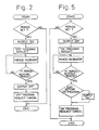
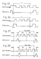
- the load 13 is required to be actuated temporarily to be in either the ON or OFF state, for example, in the ON state, hastily by the time switch, a period for which the load 13 is to be kept in the ON state is initially set by means of the period setting means 11 as shown in FIG. 2.
- the ON period of the load 13 is set by the period setting means 11, this ON period setting is detected by the setting detecting means 15 and, in response thereto, the timer means 16 starts its time-counting.
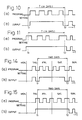
- the load 13 is driven by an output of the timer means 16 through the output control means 17, and the load 13 is thereby caused to shift into the ON state as in time chart (b) of FIG. 3 against such program control as in time chart (a) of FIG. 3.
- This ON state is retained for a set period of T, the time counting is kept continued by the timer means 16, and any control output from the program control means 14 is to be ignored during the time-counting by the timer means 16. That is, from starting time t1 to terminating time t2 of the set period T, the program control even so set as to make the ON and OFF operation twice, for example, as shown in the time chart (a) of FIG. 3 is to be ignored so that the load 13 will be maintained in the ON state over the whole of the set period T.
- the time counting by means of the timer means 16 is terminated so that its output will be at low level, whereby the control means 17 is made to provide no driving output to the load 13 which is thus to be turned into the OFF state. Thereafter, the output is again provided from the program control means 14 to the output control means 17, so that the program control will be achieved.
- the time switch of the present embodiment it is possible to have the load 13 actuated to be in temporarily OFF state.
- a period for which the load 13 is to be made off is set by the period setting means 11, this period setting is detected by the setting detecting means 15, and the timer means 16 is thereby made to start the time counting.
- the output of the timer means 16 is made at low level
- the output of the output control means 17 is also made at low level with the output from the program control means 14 ignored, and the load 13 is turned into OFF state. That is, irrespective of such program control as shown by time chart (a) of FIG.
- the load 13 is maintained in the OFF state for the set period T as shown by time chart (b) of FIG. 6.
- the time counting by the timer means 16 is terminated, the control output of the program control means 14 is provided again to the output control means 17, and the load 13 is subjected to the program control.
- the load 13 which has been made in the ON state by the program control upon the starting time t1 of the set period T will be immediately placed in OFF state whereas the load 13 made by the program control in a state of being turned into ON upon the terminating time t2 will be immediately placed in ON state (see time charts (a) and (b) of FIG. 7).
- FIG. 8 there is shown another embodiment of the present invention, in which a program control means 24 is provided for transmitting a weekly program comprising daily programs set for every day of the week, while a period setting means 21 is arranged for setting the period T of several days with a full day as a unit, for which period a load 23 is to be maintained in ON state.
- a program control means 24 is provided for transmitting a weekly program comprising daily programs set for every day of the week, while a period setting means 21 is arranged for setting the period T of several days with a full day as a unit, for which period a load 23 is to be maintained in ON state.
- a period discrimination means 28 for discriminating the period T set
- an "ON" period setting means 29 for setting the ON period on the basis of an output of the program control means 24.
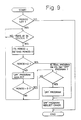
- the starting time t1 of the ON period is made to be the time when the output state of the program control means 24 has become for the first time the state of turning the load 23 ON within the set period T in an event where the output of the program control means 24 has not been in the state of turning the load 23 ON at, for example, a midnight reached
- the terminating time t2 of the ON period is made to be an output time of the program control means 24 for turning the load 23 OFF for the last time on the last day of the set period T in an event where the output of the program control means 24 has not been in a state of turning the load 23 ON upon the time when the last day of the set period T is to terminate.
- an "OFF" program transmitted from the program control means 24 to the ON period setting means 29 is to be ignored, so that the load 23 will be maintained in the ON state during the ON period.
- the output of the program control means 24 would not be in the state of turning the load 23 ON at the starting time t1 of the set period T, then the starting time of the set period T would be made the starting time of turning the load 23 ON and, provided that the output of the program control means 24 would be in the state of turning the load 23 ON upon the terminating point of the last day of the set period T, the terminating time of the ON period would be the terminating time t2 of the set period T.
- the ignoring of the "OFF" program of the program control means 24 is released so that the time switch will be automatically returned to be subjected to the program control.
- the ON period is set to be the period T, in which the load 23 is to be kept ON, for example, from a day before the first day of the period T to a next day of the last day of the period T, as represented by a time chart (a) of FIG. 3.
- Other arrangement and operation of the present embodiment are substantially the same as those in the embodiment of FIG. 1.
- FIG. 12 there is shown still another embodiment of the present invention, in which, in addition to that the period for which a load 33 is kept ON for several days in accordance with a weekly program can be set, the arrangement is so made that the period T can be set in the reservation several days before the ON period for several days of the load 33.
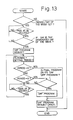
- a period setting means 31 is provided for allowing the setting reservation to be made to have the operation started, for example, on a day of a next week except the very day of the setting, while a microcomputer 32 of this time switch comprises, in addition to a period discrimination means 38 for discriminating the period T and an ON period setting means 39 for setting the ON period on the basis of an output from a program control means 34, the both means 38 and 39 being connected on rear stage side of the setting detecting means 35, a starting day of the week discriminating means 40 inserted between the setting detecting means and the period discrimination means 38.
- the load 33 is to be turned ON for two days, for example, of Friday and Saturday and also that the setting of the period and the setting of starting day of the week is to be made on Monday.
- the setting of the period and the starting day of the week is detected by the setting detecting means 35, and the set period T and starting day of the week are stored in a memory of the microcomputer 32.
- the starting day of the week discrimination means 40 it is discriminated whether or not the starting day of the week as set is reached immediately after the midnight (0 a.m.) and, when the starting day of the week is discriminated to have been reached, the load 33 is placed in the ON period, upon which such operation with respect to the load 33 as represented by time charts (a) and (b) of FIG. 14 as well as time charts (a) and (b) of FIG. 15 can be attained substantially in the same manner as in the case of FIGS. 8 and 9.
- the operation setting of the load 33 can be realized in one week ahead, for example, and the time switch of this embodiment is useful, in particular, when employed in controlling a device which requires human assistance only once or a few time in a week.
- Other arrangement and operation than those referred to in the above are substantially the same as in the foregoing embodiments.
- a program control means 44 is provided for transmitting a three-weeks program preliminarily set for every day of the week, and a period setting means 41 is arranged for setting the period T of maintaining a load 43 in OFF state for several days, with each full day as a unit.
- an "OFF" period setting means 49 for setting the OFF period on the basis of an output of the program control means 44 is provided on later stage side of a setting detecting means 45 and period discrimination means 48, and this OFF period setting means 49 discriminates whether or not the output of the program control means 44 is in a state of turning the load OFF.
- the period T will be set as a whole to be OFF period in an event where the output of the program control means 44 in the state of turning the load 43 OFF upon reaching, for example, the midnight. During this OFF period, any program provided from the program control means 44 into the means 49 is ignored and the OFF state is maintained for the set period T. When the set period T is over, the ignoring of the program is no more continued, and the program operation is automatically restored.
- the OFF period is set to be from a point when the load 43 is turned OFF by the progrom control means 44 in the set period T to a terminating point of the last day of the set period T.
- the setting of the period T by the period setting means 41 should preferably be made on a day before the starting day of the period, in the present instance, it is also possible to set the OFF period so that, when the load 43 is required to be kept in ON state from the day before the starting day over to the very starting day of the set period T, the ON state of the load 43 from the day before the set period T will continue even to a point within the set period T and the OFF state will start from the point when the ON state of the load 43 terminates to be turned OFF.
- the period setting means 41 allows the ON period of the load 43 so set as to automatically continue the ON state of the load 43 as required over a holiday. Accordingly, it becomes unnecessary, in an event where a circuit breaker is employed, to have the breaker cut off prior to the holiday for turning the load 43 OFF. Since the program control of the time switch is automatically restored when the set period T is over, it is not required for an operator to attend earlier than usual to an ON operation of the breaker, so that human labor can be saved.
- the present embodiment should involve no such risk that all program setting for the time switch must be carried out again in an event when an OFF time of the time switch due to the interruption of power supply as a result of the turning off of the load 43 by means of the breaker exceeds the backup time of the memory incorporated in the time switch.
- Other arrangement and operation of the present embodiment are substantially the same as those in the foregoing embodiments.
- the operating board 50 includes a mode switch SW1, select switch SW2, adjust switch SW3 and enter switch SW4 for setting the period for which the load 43 is made OFF, together with a display means 51 of liquid-crystal display (LCD) or the like which is readily visually confirmable, so that the setting can be carried out while observing the display.
- the switches SW1 and SW2 may be employed also for setting the time or program or operating a program monitor or the like.
- a time change switch SW5 for adjusting ⁇ 1 hour in respect of summer time
- cancel switch SW6 for cancelling any program
- manual switch SW7 for turning the load 43 ON and OFF with a manual operation, the operation of which manual switch SW7 releasing the ON or OFF state of the load 43 to have the program control state automatically restored.
- the display means 51 includes, on the other hand, hour and minute indication of time in 24 hours system, day of the week indication by means of numerals "1" through “7” at a portion below the time indication, "TIME” indication denoting that the time is presented by the time indication, “PROG” indication denoting that contents of the program are displayed by the time indication, ON indication “1” showing that the output to the load is ON, OFF indication “0” showing that the output to the load is OFF, permanent indication “P” representing that the output state is fixed to be “ON” or “OFF” by the manual switch SW7, and summer-time indication “S” denoting that the time indication is changed over to that of the summer time by means of the time change switch SW5, while a power-supply indicator 52 is further provided for showing if the power is supplied to the time switch.
- the mode switch SW1 is pressed first to select the mode.
- the time indication indicates at its hour indicating part a pair of characters "Ho" denoting the period setting mode and at minute indicating part a mark "--" as shown in FIG. 22a.
- the select switch SW2 is depressed next, the mark "--" is made to blink at, for example, 2Hz as shown in FIG. 22b so as to indicate that the period setting is possible.
- the adjust switch SW3 is depressed until an optional figure of day of days is given as shown in FIG. 22c to thereby set the period, the largest figure for which being 99.
- the enter switch SW4 is depressed to restore the time indication which is constant mode of the indication, as shown in FIG. 22d, upon which the period setting for keeping the load in OFF state is completed.
- the figure of the set period is to be indicated at the minute indicating part in the same manner as in the above, and the figure may be modified as desired by means of the adjust switch SW3.
- time indication as in FIG.
- the OFF indication "0" is made blinking upon the setting modification at the time when the mode is returned from the period setting to the time indication, so as to indicate that the period setting as intended is being carried out.
- the enter switch SW4 is to be depressed in the state where the mark "--" of the minute indicating part blinks as in FIG. 22b, and the set period is thereby cancelled at a point when the time indication is made as in FIG. 22f.
- the cancellation of the set period may be also carried out by controlling the operation of the load 43 by means of the manual switch SW7.
- the operation of the manual switch SW7 causes a permanent operation to be carried out for rendering the operating state of the load 43 to be constant continuously, irrespective of the program.
- the load 43 is controlled to be OFF.
- the load 43 is placed in ON state until the same is turned OFF by the program control, upon which an indication of the set period reached is carried out with the ON indication "1" blinked at, for example, 0.5Hz as shown in FIG. 22g.
- the manual switch SW7 is provided so that, in the case when the load 43 is required, for example, to be turned OFF before reaching holidays in an ON program from a day before the holidays through the period of the holidays, as represented by a time chart (a) of FIG. 23, the load 43 can be turned OFF by means of the manual switch SW7 at a time t3 prior to the holidays, as shown by a time chart (b) of FIG. 23.
- the arrangement also may be so made that, in such program as shown in a time chart (a) of FIG.
- the load 43 will be turned ON with the manual switch SW7 operated at a time t4 immediately after starting of the set period T but, as the output from the program control means 44 turns the load 43 OFF thereafter, this OFF state will be maintained.
- the manual switch SW7 may also be arranged for actuating the load 43 so as to have its state reversed upon operation of the switch.
- FIG. 21 there is shown a two-circuit output type operating board 50 to be employed in the time switch in the embodiment of FIG. 16, in which arrangements and operation of the board are substantially the same as those of the board of FIG. 20, except for that two manual switches SW7A and SW7B are provided and a pair of permanent indications are included in the display means 51 in correspondence to the manual switches.
- a program control means 64 is provided for transmitting a weekly program set preliminarily for every day of the week, and a period setting means 61 allows a reservation setting of the period T to be made so as to maintain the load 63 in OFF state for several days with each full day as a unit.
- the period setting means 61 is also provided for reservation setting of the period T so as to have the OFF state of the load started, for example, from any desired day of a next week except for the very day of the setting, while a microcomputer 62 includes, on later stage side of a setting detecting means 61, a period discrimination means 68 for discriminating the set period T, an "OFF" period setting means 69 for setting the OFF period on the basis of an output from a program control means 64 and, on earlier stage side of these means 68 and 69, a starting day of the week discrimination means 70.
- FIGS. 26 and 27 it should be appreciated that the present embodiment is substantially the same in the arrangement and operation as those in the foregoing embodiment of FIG. 16 as will be clear when FIGS. 16-18 are compared, except for that the load 63 is set in "OFF" state instead of ON state in carrying out on, for example, Monday the reservation setting of the load for two days of Friday and Saturday.
- an operating board 111 includes a display means 113 disposed in upper part of the board, a plurality of switches SW11-SW16 arranged below the display means 113, and connecting terminals 114 mounted to lower part of the board for connection thereto of wires from a power source and a load.
- the time switch comprises a casing of a body 120 and a cover 121 fitted onto the body 120, in which a printed circuit board 122 mounted to the body 120 carries thereon the display means 113 and output controlling relay 123 and so on.
- terminal plates 114a of the connecting terminals 114 are connected directly to printed circuits on the printed circuit board 122, and a shiftable lid 121a is mounted to the cover 121 at a part of covering the connecting terminals 114.
- the OFF period setting of the load 63 is carried out by means of the mode switch SW11, select switch SW12 and set switch SW13, with the display means 113 being visually confirmed.
- These switches SW11-SW13 may also be employed for setting the time, program, program monitoring and so on.
- the switch SW14 is employed as a call switch for having contents of the program displayed at the display means 113 so as to monitor the program, the switch SW15 as a manual switch for manually making the load 63 ON and OFF, and the switch SW16 as an output state change-over switch for changing over signals for controlling the load 63 between a timer output and a pulse output, respectively.
- the timer output is the foregoing output used upon setting the period, while the pulse output is the one for making the load pulsatingly ON, and the period setting under the use of the pulse output is also to be carried out with the foregoing switches SW11-SW13.
- the display means 113 further, there are arranged respective parts for time indication in 24 hour system with hour, minute and second displays, days of the week indication below the time indication part with "MON”, “TUE”, ... "SUN” displays, "TIME” indication denoting the mode of the time setting, "PROGRAM” indication denoting the mode selected for the program setting, "CALL” indication denoting the mode that the set program is being called, "MONITOR” indication denoting the mode of operation confirming in the set program, "ON” indication denoting that the output to the load 63 is in ON state, “OFF” indication denoting that the output to the load 63 is in OFF state, a permanent “P” indication representing that the load 63 is fixed by the manual switch SW16 in the ON or OFF state, and a summer time indication denoting with a sun mark that the time indication is set to be of the summer time.
- TIME indication denoting the mode of the time setting
- PROGRAM indication denoting the mode selected for the program setting
- the mode switch SW11 is depressed first to select the period setting mode, upon which letters "Ho" and a mark "--" are displayed at the hour and minute displays of the time indication part of the display means 113, as shown in FIG. 33a.
- the select switch SW12 is depressed here, the mark "--" of the minute display is made to blink at, for example, 2Hz as shown in FIG. 33b, whereby it is indicated that the period setting is now made possible.
- a depression next of the set switch SW13 allows the period to be set for an optional figure of days as shown in FIG. 33c, the largest figure of the days of the period being 99.
- the select switch SW12 is pushed again so that the "MON" display of the day of the week indication part will be blinked at, for example, 2Hz as shown in FIG. 33d so as to represent that the reservation setting of the OFF period has been made on Monday, as well as that the setting of the day of the week on which the set period should start is now settable.
- the set switch SW13 is depressed further to select another day of the following week, except Monday (see FIG. 33e).
- the mode switch SW11 is again depressed to change over the mode to the constant mode, whereby the setting of the period T and starting day of the week is completed, present time and operating state of the load 63 are indicated as in FIG. 33f, with the "FRI" display denoting the starting day of the week blinked at, for example, 0.5Hz and the reservation setting of the OFF period is to be confirmed.
- the blinking of the "FRI" display at the day of the week indication part stops, whereas the "OFF" indication part starts blinking at, for example, 0.5Hz to represent that the set period for the OFF state of the load has been reached.
- the manual switch SW15 is depressed, for example, to render the load to be continuously kept in OFF state and thus to carry out the permanent OFF operation, then the "P" and "OFF" indications are made as shown in FIG. 34, denoting that the permanent OFF operation has been made.
- Such indications are made different from an indication of the OFF state of the load in accordance with the set period, so that the OFF state of the load 63 due to the permanent OFF operation can be recognized. It is preferable here that the arrangement is so made as to have the "OFF" indication not blinked upon the permanent OFF operation.
Abstract
Description
- This invention relates to a time switch which incorporates therein a microcomputer for controlling the operation of a load in accordance with a program, and also for causing the load operated temporarily in a desired state independently of the program.
- The time switch of the kind referred to can be effectively employed in setting ON and OFF state of loads used in a factory, building and so on in a relatively long term range.
- A variety of the time switch incorporating the microcomputer for controlling the ON and OFF operation of the load for a relatively long period in accordance with a predetermined program have become more often employed in recent days, the time switches of this kind are arranged for controlling the load operation with the program which is generally set for every day of the week and carried out for every week, ten days or month as one cycle. In practice, it happens that the load being in, for example, OFF state in accordance with the program is required to be turned into ON state for a predetermined period with the program ignored, and a measure for such requirement has been taken by means of a manual switch provided in the time switch or a switch connected in parallel with respect to an output of the time switch for such temporary ON operation. In turning the load temporarily into the ON state, for example, there has been, however, involved a drawback that the turning of the load into, for example, ON state as in the above requires two actions before and after the turning ON to render the operation complicated. In an event where the ON and OFF operation of the load is set by the program control to be carried out more than once in a set period, for example, and the load is demanded to be kept in ON state substantially over the entire set period from starting time t1 to terminating time t2, the load has to be turned ON subsequent to the starting time t1 and prior to the terminating time t2 according to the program control, and it becomes necessary to carry out the operation twice including the ON operation upon the starting time t1 and the OFF operation upon the terminating time t2. If the operation upon the terminating time t2 is forgotten, there arises a risk that the program control of the load is not carried out so as to cause a problem to occur in that the operation of the load involves a trouble.
- In Japanese Utility Model Application Laid-Open Publication No. 59-115386, for example, there has been disclosed a time switch made ON and OFF forcibly by an external signal, but this time switch also is to be involved in the same problem as in the above once the OFF operation is foregotten upon the termination of the set period. In another Japanese Patent Application Laid-Open Publication No. 61-278784, further, there has been disclosed a time switch which can set the program for every day of the week and allows a temporary input of a separate program to be utilized but cancelled after a predetermined operation. However, this time switch also involves the same problem as in the case of the manual switch employed for the temporary ON operation, and further requires a re-writing of the program so as to render the operation more complicated.
- In turning the time switch into OFF state, for example, from its ON state made according to the program, on the other hand, the OFF operation may happen to be attained by means of a breaker connected to a power source. If the time switch is set to turn the load ON and OFF at a predetermined time in every one of several days, this measure may be taken in order to have the load temporarily turned hastily for more than one day. However, this measure also involves a problem that the operation thereof is similarly complicated to the foregoing time switches in respect of the twice required operation upon the OFF and ON operation of the load and, when the load requires a warming up operation, the breaker is required to be made ON considerably much earlier than starting time of ordinary business hours so as to necessitate extra early time service. Since the OFF operation of the breaker also renders the power source incorporated in the time switch to be made OFF, it becomes necessary to carry out a re-entry of input of the program upon initiation of the business hours in an event where the temporary OFF operation exceeds the back-up hours of the program memory.
- An object of the present invention is, therefore, to provide a time switch which allows the load to be temporarily made ON or OFF with the foregoing problems removed and with a simpler operation while also allowing the operation by the program control reliably restored.
- According to the present invention, this object can be realized by a time switch in which the load can be operated through an output control means which controls the load operation with a program control means on the basis of a preliminarily set program, characterized in that a period for which the load is to be turned either into ON or OFF state is set by a period setting means independent of the program preliminarily set, the period setting is detected by a setting detecting means, a timer means carries out time counting for the set period and provides to an output control means an output for maintaining the load in either the ON or OFF state for the set period, and an output of the program control means is provided again to the output control means when the set period is over.
-
- FIGURE 1 is a block diagram of an embodiment of the time switch according to the present invention;
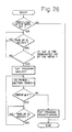
- FIG. 2 is a flow chart of the operation of the time switch of FIG. 1;
- FIGS. 3 and 4 are time charts of the operation of the time switch of FIG. 1;
- FIG. 5 is a flow chart of the operation in another working aspect of the present invention;
- FIGS. 7 and 7 are time charts of the operation of the working aspect of FIG. 5;
- FIG. 8 is a block diagram of the time switch in another embodiment of the present invention;
- FIG. 9 is a flow chart of the operation of the time switch in FIG. 8;
- FIGS. 10 and 11 are time charts of the operation of the time switch of FIG. 8;
- FIG. 12 is a block diagram of still another embodiment of the present invention;
- FIG. 13 is a flow chart of the operation of the time switch of FIG. 12;
- FIGS. 14 and 15 are time charts of the operation of the time switch of FIG. 12;
- FIG. 16 is a block diagram of a further embodiment of the present invention;
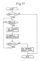
- FIG. 17 is a flow chart of the operation of the time switch of FIG. 16;
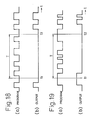
- FIGS. 18 and 19 are time charts of the operation of the time switch of FIG. 16;
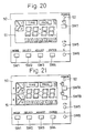
- FIG. 20 shows in a plan view an operating board of the time switch in a single circuit output type according to the present invention;
- FIG. 21 shows in a plan view an operating board of the time switch in a two-circuit output type according to the present invention;
- FIGS. 22a-22g are explanatory views for the operation of a display means in the operating board of FIG. 20 or 21;
- FIGS. 23 and 24 are time charts of the operation of the time switch according to the present invention in which a manual switch is employed;
- FIG. 25 is a block diagram of a still further embodiment of the present invention;
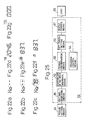
- FIG. 26 is a flow chart of the operation of the time switch in FIG. 25;
- FIGS. 27 and 28 are time charts of the operation of the time switch in FIG. 25;
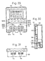
- FIGS. 29-32 show in a plan view, vertically sectioned view, bottom view and rear view, respectively, the time switch in FIG. 25; and
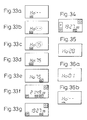
- FIGS. 33a-33g, 34, 35, 36a and 36b are explanatory views for the operation of a display means in the operating board of the time switch in FIG. 25, respectively.
- Referring to FIG. 1, an embodiment of the time switch according to the present invention generally comprises a period setting means 11, a
microcomputer 12 connected to the period setting means 11, and aload 13 connected through thismicrocomputer 12 also to themeans 11. Themicrocomputer 12 incorporates a program control means 14 which may be of a well known type that controls the operation of theload 13 in accordance with a preliminarily set program. In the present instance, the period setting means 11 is provided to be capable of setting a period for which theload 13 is kept in either one of ON and OFF states independently of the program control means 14, and the setting operation of the period setting means 11 is detected by a setting detecting means 15 also incorporated in themicrocomputer 12. An output of this setting detecting means 15 is provided to a timer means 16 in themicrocomputer 12, the timer means 16 counts time during the set period of time, and an output for keeping theload 13 at either the ON or OFF state during the set period is provided from the timer means 16 to an output control means 17. Theload 13 is connected directly to this output control means 17, so that theload 13 will be driven in response to an output from the program control means 14 and the output from the timer means 16. - In the above time switch, normally, the
load 13 can be program-controlled for each of such various periods as weekly, 10 days, monthly and any longer cycles. When, on the other hand, theload 13 is required to be actuated temporarily to be in either the ON or OFF state, for example, in the ON state, hastily by the time switch, a period for which theload 13 is to be kept in the ON state is initially set by means of the period setting means 11 as shown in FIG. 2. As the ON period of theload 13 is set by the period setting means 11, this ON period setting is detected by the setting detecting means 15 and, in response thereto, the timer means 16 starts its time-counting. Simultaneously with the starting of the time counting of thetimer 16, theload 13 is driven by an output of the timer means 16 through the output control means 17, and theload 13 is thereby caused to shift into the ON state as in time chart (b) of FIG. 3 against such program control as in time chart (a) of FIG. 3. This ON state is retained for a set period of T, the time counting is kept continued by the timer means 16, and any control output from the program control means 14 is to be ignored during the time-counting by the timer means 16. That is, from starting time t1 to terminating time t2 of the set period T, the program control even so set as to make the ON and OFF operation twice, for example, as shown in the time chart (a) of FIG. 3 is to be ignored so that theload 13 will be maintained in the ON state over the whole of the set period T. - As the set period T is over, the time counting by means of the timer means 16 is terminated so that its output will be at low level, whereby the control means 17 is made to provide no driving output to the
load 13 which is thus to be turned into the OFF state. Thereafter, the output is again provided from the program control means 14 to the output control means 17, so that the program control will be achieved. - Further, when the
load 13 is to be kept in ON state over the entire set period T and in an event when theload 13 is already in the ON state at the starting time t1 of the set period T as shown in time chart (a) of FIG. 4, this ON state of theload 13 is kept continued. Even in an event where, on the other hand, theload 13 is to be kept in the ON state upon the terminating time t2, such program control output of keeping the ON state is ignored so that theload 13 will be made to shift to the OFF state, the program control is restored as the ON state keeping period of the program control is over, so as to accomplish the program control, so that such output as shown by time chart (b) of FIG. 4 will be provided out of the output control means 14. - According to the time switch of the present embodiment, it is possible to have the
load 13 actuated to be in temporarily OFF state. In this case, as shown in FIG. 5, a period for which theload 13 is to be made off is set by the period setting means 11, this period setting is detected by thesetting detecting means 15, and the timer means 16 is thereby made to start the time counting. As the timer means 16 starts the counting, the output of the timer means 16 is made at low level, the output of the output control means 17 is also made at low level with the output from the program control means 14 ignored, and theload 13 is turned into OFF state. That is, irrespective of such program control as shown by time chart (a) of FIG. 6, theload 13 is maintained in the OFF state for the set period T as shown by time chart (b) of FIG. 6. As the set period T is over, the time counting by the timer means 16 is terminated, the control output of the program control means 14 is provided again to the output control means 17, and theload 13 is subjected to the program control. At this time, theload 13 which has been made in the ON state by the program control upon the starting time t1 of the set period T will be immediately placed in OFF state whereas theload 13 made by the program control in a state of being turned into ON upon the terminating time t2 will be immediately placed in ON state (see time charts (a) and (b) of FIG. 7). - In FIG. 8, there is shown another embodiment of the present invention, in which a program control means 24 is provided for transmitting a weekly program comprising daily programs set for every day of the week, while a period setting means 21 is arranged for setting the period T of several days with a full day as a unit, for which period a
load 23 is to be maintained in ON state. In the present embodiment, further, there are provided at following stage to a setting detecting means 25 a period discrimination means 28 for discriminating the period T set and an "ON" period setting means 29 for setting the ON period on the basis of an output of the program control means 24. At this ON period setting means 29, it is discriminated whether or not the output of the program control means 24 is in a state of turning the load ON. Referring also to a flow chart of FIG. 9 and a time chart (a) of FIG. 10, the starting time t1 of the ON period is made to be the time when the output state of the program control means 24 has become for the first time the state of turning theload 23 ON within the set period T in an event where the output of the program control means 24 has not been in the state of turning theload 23 ON at, for example, a midnight reached, and the terminating time t2 of the ON period is made to be an output time of the program control means 24 for turning theload 23 OFF for the last time on the last day of the set period T in an event where the output of the program control means 24 has not been in a state of turning theload 23 ON upon the time when the last day of the set period T is to terminate. Further, in the above ON period, an "OFF" program transmitted from the program control means 24 to the ON period setting means 29 is to be ignored, so that theload 23 will be maintained in the ON state during the ON period. Provided here that the output of the program control means 24 would not be in the state of turning theload 23 ON at the starting time t1 of the set period T, then the starting time of the set period T would be made the starting time of turning theload 23 ON and, provided that the output of the program control means 24 would be in the state of turning theload 23 ON upon the terminating point of the last day of the set period T, the terminating time of the ON period would be the terminating time t2 of the set period T. As the set period T is over, the ignoring of the "OFF" program of the program control means 24 is released so that the time switch will be automatically returned to be subjected to the program control. - In an event where the
load 23 is to be turned ON by the program control means 24 upon the starting and terminating points of the set period T as represented by a time chart (a) of FIG. 11, the ON period is set to be the period T, in which theload 23 is to be kept ON, for example, from a day before the first day of the period T to a next day of the last day of the period T, as represented by a time chart (a) of FIG. 3. Other arrangement and operation of the present embodiment are substantially the same as those in the embodiment of FIG. 1. - In FIG. 12, there is shown still another embodiment of the present invention, in which, in addition to that the period for which a
load 33 is kept ON for several days in accordance with a weekly program can be set, the arrangement is so made that the period T can be set in the reservation several days before the ON period for several days of theload 33. In this case, a period setting means 31 is provided for allowing the setting reservation to be made to have the operation started, for example, on a day of a next week except the very day of the setting, while amicrocomputer 32 of this time switch comprises, in addition to a period discrimination means 38 for discriminating the period T and an ON period setting means 39 for setting the ON period on the basis of an output from a program control means 34, the both means 38 and 39 being connected on rear stage side of thesetting detecting means 35, a starting day of the week discriminating means 40 inserted between the setting detecting means and the period discrimination means 38. Referring further to a flow chart of FIG. 13 and time charts (a) and (b) of FIG. 4 in conjunction, it is assumed here that theload 33 is to be turned ON for two days, for example, of Friday and Saturday and also that the setting of the period and the setting of starting day of the week is to be made on Monday. In the present embodiment, too, the setting of the period and the starting day of the week is detected by thesetting detecting means 35, and the set period T and starting day of the week are stored in a memory of themicrocomputer 32. In the starting day of the week discrimination means 40, it is discriminated whether or not the starting day of the week as set is reached immediately after the midnight (0 a.m.) and, when the starting day of the week is discriminated to have been reached, theload 33 is placed in the ON period, upon which such operation with respect to theload 33 as represented by time charts (a) and (b) of FIG. 14 as well as time charts (a) and (b) of FIG. 15 can be attained substantially in the same manner as in the case of FIGS. 8 and 9. - According to the arrangement of the present embodiment, the operation setting of the
load 33 can be realized in one week ahead, for example, and the time switch of this embodiment is useful, in particular, when employed in controlling a device which requires human assistance only once or a few time in a week. Other arrangement and operation than those referred to in the above are substantially the same as in the foregoing embodiments. - In a further embodiment of the present invention shown in FIG. 16, a program control means 44 is provided for transmitting a three-weeks program preliminarily set for every day of the week, and a period setting means 41 is arranged for setting the period T of maintaining a
load 43 in OFF state for several days, with each full day as a unit. In the present instance, an "OFF" period setting means 49 for setting the OFF period on the basis of an output of the program control means 44 is provided on later stage side of asetting detecting means 45 and period discrimination means 48, and this OFF period setting means 49 discriminates whether or not the output of the program control means 44 is in a state of turning the load OFF. Referring also in conjunction to a flow chart of FIG. 17 and time charts (a) and (b) of FIG. 18, the period T will be set as a whole to be OFF period in an event where the output of the program control means 44 in the state of turning theload 43 OFF upon reaching, for example, the midnight. During this OFF period, any program provided from the program control means 44 into themeans 49 is ignored and the OFF state is maintained for the set period T. When the set period T is over, the ignoring of the program is no more continued, and the program operation is automatically restored. - When the output of the program control means 44 is in the state of turning the
load 43 ON upon reaching the midnight, as shown in a time chart (a) of FIG. 19, on the other hand, the OFF period is set to be from a point when theload 43 is turned OFF by the progrom control means 44 in the set period T to a terminating point of the last day of the set period T. That is, while the setting of the period T by the period setting means 41 should preferably be made on a day before the starting day of the period, in the present instance, it is also possible to set the OFF period so that, when theload 43 is required to be kept in ON state from the day before the starting day over to the very starting day of the set period T, the ON state of theload 43 from the day before the set period T will continue even to a point within the set period T and the OFF state will start from the point when the ON state of theload 43 terminates to be turned OFF. - According to the present embodiment, further, the period setting means 41 allows the ON period of the
load 43 so set as to automatically continue the ON state of theload 43 as required over a holiday. Accordingly, it becomes unnecessary, in an event where a circuit breaker is employed, to have the breaker cut off prior to the holiday for turning theload 43 OFF. Since the program control of the time switch is automatically restored when the set period T is over, it is not required for an operator to attend earlier than usual to an ON operation of the breaker, so that human labor can be saved. Further, the present embodiment should involve no such risk that all program setting for the time switch must be carried out again in an event when an OFF time of the time switch due to the interruption of power supply as a result of the turning off of theload 43 by means of the breaker exceeds the backup time of the memory incorporated in the time switch. Other arrangement and operation of the present embodiment are substantially the same as those in the foregoing embodiments. - Referring next to FIG. 20, there is shown an operating
board 50 of a single circuit output type which is employable in the time switch of the embodiment in FIG. 16. The operatingboard 50 includes a mode switch SW1, select switch SW2, adjust switch SW3 and enter switch SW4 for setting the period for which theload 43 is made OFF, together with a display means 51 of liquid-crystal display (LCD) or the like which is readily visually confirmable, so that the setting can be carried out while observing the display. In the present instance, the switches SW1 and SW2 may be employed also for setting the time or program or operating a program monitor or the like. Further, there are also provided a time change switch SW5 for adjusting ±1 hour in respect of summer time, cancel switch SW6 for cancelling any program, and manual switch SW7 for turning theload 43 ON and OFF with a manual operation, the operation of which manual switch SW7 releasing the ON or OFF state of theload 43 to have the program control state automatically restored. - The display means 51 includes, on the other hand, hour and minute indication of time in 24 hours system, day of the week indication by means of numerals "1" through "7" at a portion below the time indication, "TIME" indication denoting that the time is presented by the time indication, "PROG" indication denoting that contents of the program are displayed by the time indication, ON indication "1" showing that the output to the load is ON, OFF indication "0" showing that the output to the load is OFF, permanent indication "P" representing that the output state is fixed to be "ON" or "OFF" by the manual switch SW7, and summer-time indication "S" denoting that the time indication is changed over to that of the summer time by means of the time change switch SW5, while a power-
supply indicator 52 is further provided for showing if the power is supplied to the time switch. - In setting the period for which the
load 43 is made OFF by means of the operatingboard 50 of the present embodiment, the mode switch SW1 is pressed first to select the mode. When a period setting mode is thereby selected, the time indication indicates at its hour indicating part a pair of characters "Ho" denoting the period setting mode and at minute indicating part a mark "--" as shown in FIG. 22a. As the select switch SW2 is depressed next, the mark "--" is made to blink at, for example, 2Hz as shown in FIG. 22b so as to indicate that the period setting is possible. The adjust switch SW3 is depressed until an optional figure of day of days is given as shown in FIG. 22c to thereby set the period, the largest figure for which being 99. After the setting of the period, the enter switch SW4 is depressed to restore the time indication which is constant mode of the indication, as shown in FIG. 22d, upon which the period setting for keeping the load in OFF state is completed. In modifying the set period, the figure of the set period is to be indicated at the minute indicating part in the same manner as in the above, and the figure may be modified as desired by means of the adjust switch SW3. In an event where the period for which theload 43 is to be OFF has not been reached upon the above modification, such time indication as in FIG. 22d is carried out, whereas, in an event where the OFF period of theload 43 has been reached, the OFF indication "0" is made blinking upon the setting modification at the time when the mode is returned from the period setting to the time indication, so as to indicate that the period setting as intended is being carried out. - At the time when a previously set period is required to be cancelled, the enter switch SW4 is to be depressed in the state where the mark "--" of the minute indicating part blinks as in FIG. 22b, and the set period is thereby cancelled at a point when the time indication is made as in FIG. 22f. The cancellation of the set period may be also carried out by controlling the operation of the
load 43 by means of the manual switch SW7. In this case, the operation of the manual switch SW7 causes a permanent operation to be carried out for rendering the operating state of theload 43 to be constant continuously, irrespective of the program. When the set period starts, theload 43 is controlled to be OFF. In the event when there is present a program which turns theload 43 ON between the set period and the day before the period, as has been partly disclosed, theload 43 is placed in ON state until the same is turned OFF by the program control, upon which an indication of the set period reached is carried out with the ON indication "1" blinked at, for example, 0.5Hz as shown in FIG. 22g. - In the present embodiment, the manual switch SW7 is provided so that, in the case when the
load 43 is required, for example, to be turned OFF before reaching holidays in an ON program from a day before the holidays through the period of the holidays, as represented by a time chart (a) of FIG. 23, theload 43 can be turned OFF by means of the manual switch SW7 at a time t3 prior to the holidays, as shown by a time chart (b) of FIG. 23. The arrangement also may be so made that, in such program as shown in a time chart (a) of FIG. 24 in which the set period T is made to be a part of the holidays, theload 43 will be turned ON with the manual switch SW7 operated at a time t4 immediately after starting of the set period T but, as the output from the program control means 44 turns theload 43 OFF thereafter, this OFF state will be maintained. The manual switch SW7 may also be arranged for actuating theload 43 so as to have its state reversed upon operation of the switch. - In FIG. 21, there is shown a two-circuit output
type operating board 50 to be employed in the time switch in the embodiment of FIG. 16, in which arrangements and operation of the board are substantially the same as those of the board of FIG. 20, except for that two manual switches SW7A and SW7B are provided and a pair of permanent indications are included in the display means 51 in correspondence to the manual switches. - In a still further embodiment of the present invention as shown in FIG. 25, a program control means 64 is provided for transmitting a weekly program set preliminarily for every day of the week, and a period setting means 61 allows a reservation setting of the period T to be made so as to maintain the
load 63 in OFF state for several days with each full day as a unit. The period setting means 61 is also provided for reservation setting of the period T so as to have the OFF state of the load started, for example, from any desired day of a next week except for the very day of the setting, while amicrocomputer 62 includes, on later stage side of asetting detecting means 61, a period discrimination means 68 for discriminating the set period T, an "OFF" period setting means 69 for setting the OFF period on the basis of an output from a program control means 64 and, on earlier stage side of thesemeans load 63 is set in "OFF" state instead of ON state in carrying out on, for example, Monday the reservation setting of the load for two days of Friday and Saturday. - In FIGS. 29-32, outer appearance of the time switch in the embodiment of FIG. 25 is shown, in which an
operating board 111 includes a display means 113 disposed in upper part of the board, a plurality of switches SW11-SW16 arranged below the display means 113, and connectingterminals 114 mounted to lower part of the board for connection thereto of wires from a power source and a load. The time switch comprises a casing of abody 120 and acover 121 fitted onto thebody 120, in which a printedcircuit board 122 mounted to thebody 120 carries thereon the display means 113 andoutput controlling relay 123 and so on. In this case, terminal plates 114a of the connectingterminals 114 are connected directly to printed circuits on the printedcircuit board 122, and ashiftable lid 121a is mounted to thecover 121 at a part of covering the connectingterminals 114. - In the
present operating board 111, the OFF period setting of theload 63 is carried out by means of the mode switch SW11, select switch SW12 and set switch SW13, with the display means 113 being visually confirmed. These switches SW11-SW13 may also be employed for setting the time, program, program monitoring and so on. In other switches, the switch SW14 is employed as a call switch for having contents of the program displayed at the display means 113 so as to monitor the program, the switch SW15 as a manual switch for manually making theload 63 ON and OFF, and the switch SW16 as an output state change-over switch for changing over signals for controlling theload 63 between a timer output and a pulse output, respectively. Here, the timer output is the foregoing output used upon setting the period, while the pulse output is the one for making the load pulsatingly ON, and the period setting under the use of the pulse output is also to be carried out with the foregoing switches SW11-SW13. - In the display means 113, further, there are arranged respective parts for time indication in 24 hour system with hour, minute and second displays, days of the week indication below the time indication part with "MON", "TUE", ... "SUN" displays, "TIME" indication denoting the mode of the time setting, "PROGRAM" indication denoting the mode selected for the program setting, "CALL" indication denoting the mode that the set program is being called, "MONITOR" indication denoting the mode of operation confirming in the set program, "ON" indication denoting that the output to the
load 63 is in ON state, "OFF" indication denoting that the output to theload 63 is in OFF state, a permanent "P" indication representing that theload 63 is fixed by the manual switch SW16 in the ON or OFF state, and a summer time indication denoting with a sun mark that the time indication is set to be of the summer time. - In carrying out the reservation setting of the period for which the
load 63 is made OFF by means of the operatingboard 111 of the present embodiment, the mode switch SW11 is depressed first to select the period setting mode, upon which letters "Ho" and a mark "--" are displayed at the hour and minute displays of the time indication part of the display means 113, as shown in FIG. 33a. As the select switch SW12 is depressed here, the mark "--" of the minute display is made to blink at, for example, 2Hz as shown in FIG. 33b, whereby it is indicated that the period setting is now made possible. A depression next of the set switch SW13 allows the period to be set for an optional figure of days as shown in FIG. 33c, the largest figure of the days of the period being 99. After this period setting, the select switch SW12 is pushed again so that the "MON" display of the day of the week indication part will be blinked at, for example, 2Hz as shown in FIG. 33d so as to represent that the reservation setting of the OFF period has been made on Monday, as well as that the setting of the day of the week on which the set period should start is now settable. Here, the set switch SW13 is depressed further to select another day of the following week, except Monday (see FIG. 33e). Next, the mode switch SW11 is again depressed to change over the mode to the constant mode, whereby the setting of the period T and starting day of the week is completed, present time and operating state of theload 63 are indicated as in FIG. 33f, with the "FRI" display denoting the starting day of the week blinked at, for example, 0.5Hz and the reservation setting of the OFF period is to be confirmed. - Provided now that the starting day of the week of the set operation of the load, i.e., Friday here has been reached, the blinking of the "FRI" display at the day of the week indication part stops, whereas the "OFF" indication part starts blinking at, for example, 0.5Hz to represent that the set period for the OFF state of the load has been reached. When the manual switch SW15 is depressed, for example, to render the load to be continuously kept in OFF state and thus to carry out the permanent OFF operation, then the "P" and "OFF" indications are made as shown in FIG. 34, denoting that the permanent OFF operation has been made. Such indications are made different from an indication of the OFF state of the load in accordance with the set period, so that the OFF state of the
load 63 due to the permanent OFF operation can be recognized. It is preferable here that the arrangement is so made as to have the "OFF" indication not blinked upon the permanent OFF operation. - In an event when a modification of the set OFF period is called for, this may be practiced in the same steps as in the case of the foregoing reservation setting of the OFF period. When the set period T has already been reached upon the modification, the setting of the starting day of the week is no more required and the day of the week is not displayed, as seen in FIG. 35. In the display means 113, further, the figure of the days at the time indication part is subjected, in the period set mode, to one decrement at every moment when the midnight, i.e., 24 o'clock is passed and, as 24 o'clock of the last day of the set period is passed, the minute display is changed from the display of the day figure as in FIG. 36a to the display of the mark "--" as in FIG. 36b, so that the starting of the set OFF period can be visually confirmed.
- In the time switch according to the present invention, various design modification can be made. For example, such arrangement of the operating board as shown in FIGS. 20, 21 and 29 just as examples may properly be altered in respect of the arrangements of the indication parts and various switches. The embodiment of FIG. 29 can be modified to be of the two circuit output type, and the embodiment of FIG. 20 or 29 may even be modified, if required, to be of an output type of three or more circuits, as will be readily appreciated by any person skilled in the art.
Claims (9)
Applications Claiming Priority (4)
| Application Number | Priority Date | Filing Date | Title |
|---|---|---|---|
| JP331284/88 | 1988-12-29 | ||
| JP33128488 | 1988-12-29 | ||
| JP27245789A JPH02269994A (en) | 1988-12-29 | 1989-10-19 | Time switch |
| JP272457/89 | 1989-10-19 |
Publications (3)
| Publication Number | Publication Date |
|---|---|
| EP0376409A2 true EP0376409A2 (en) | 1990-07-04 |
| EP0376409A3 EP0376409A3 (en) | 1991-01-30 |
| EP0376409B1 EP0376409B1 (en) | 1993-11-10 |
Family
ID=26550212
Family Applications (1)
| Application Number | Title | Priority Date | Filing Date |
|---|---|---|---|
| EP19890203333 Expired - Lifetime EP0376409B1 (en) | 1988-12-29 | 1989-12-27 | Time switch |
Country Status (3)
| Country | Link |
|---|---|
| EP (1) | EP0376409B1 (en) |
| JP (1) | JPH02269994A (en) |
| DE (1) | DE68910661T2 (en) |
Cited By (5)
| Publication number | Priority date | Publication date | Assignee | Title |
|---|---|---|---|---|
| WO1995007500A1 (en) * | 1993-09-04 | 1995-03-16 | Energy Management Team Ag | Method and device for minimizing the energy consumption of an electrical load |
| USD634276S1 (en) | 2009-06-05 | 2011-03-15 | Leviton Manufacturing Co., Inc. | Electrical device |
| USD640640S1 (en) | 2009-10-28 | 2011-06-28 | Leviton Manufacturing Co., Inc. | Electrical device |
| US8050145B2 (en) | 2008-02-26 | 2011-11-01 | Leviton Manufacturing Co., Inc. | Wall mounted programmable timer system |
| US8786137B2 (en) | 2009-09-11 | 2014-07-22 | Leviton Manufacturing Co., Inc. | Digital wiring device |
Citations (2)
| Publication number | Priority date | Publication date | Assignee | Title |
|---|---|---|---|---|
| GB2064165A (en) * | 1979-11-27 | 1981-06-10 | Amure K O | Time Switch Apparatus |
| JPS57172282A (en) * | 1981-04-17 | 1982-10-23 | Hitachi Ltd | Timer for thermal accumulator |
-
1989
- 1989-10-19 JP JP27245789A patent/JPH02269994A/en active Pending
- 1989-12-27 DE DE1989610661 patent/DE68910661T2/en not_active Expired - Lifetime
- 1989-12-27 EP EP19890203333 patent/EP0376409B1/en not_active Expired - Lifetime
Patent Citations (2)
| Publication number | Priority date | Publication date | Assignee | Title |
|---|---|---|---|---|
| GB2064165A (en) * | 1979-11-27 | 1981-06-10 | Amure K O | Time Switch Apparatus |
| JPS57172282A (en) * | 1981-04-17 | 1982-10-23 | Hitachi Ltd | Timer for thermal accumulator |
Non-Patent Citations (1)
| Title |
|---|
| PATENT ABSTRACTS OF JAPAN, vol. 7, no. 18 (P-170)[1163], 25th January 1983; & JP-A-57 172 282 (HITACHI SEISAKUSHO K.K.) 23-10-1982 * |
Cited By (9)
| Publication number | Priority date | Publication date | Assignee | Title |
|---|---|---|---|---|
| WO1995007500A1 (en) * | 1993-09-04 | 1995-03-16 | Energy Management Team Ag | Method and device for minimizing the energy consumption of an electrical load |
| US5673202A (en) * | 1993-09-04 | 1997-09-30 | Energy Management Team Ag | System for minimizing the energy consumption of an electrical load |
| US8050145B2 (en) | 2008-02-26 | 2011-11-01 | Leviton Manufacturing Co., Inc. | Wall mounted programmable timer system |
| US10048653B2 (en) | 2008-02-26 | 2018-08-14 | Leviton Manufacturing Company, Inc. | Wall mounted programmable timer system |
| USD634276S1 (en) | 2009-06-05 | 2011-03-15 | Leviton Manufacturing Co., Inc. | Electrical device |
| USD646231S1 (en) | 2009-06-05 | 2011-10-04 | Leviton Manufacturing Co., Inc. | Electrical device |
| USD656102S1 (en) | 2009-06-05 | 2012-03-20 | Leviton Manufacturing Co., Inc. | Electrical device |
| US8786137B2 (en) | 2009-09-11 | 2014-07-22 | Leviton Manufacturing Co., Inc. | Digital wiring device |
| USD640640S1 (en) | 2009-10-28 | 2011-06-28 | Leviton Manufacturing Co., Inc. | Electrical device |
Also Published As
| Publication number | Publication date |
|---|---|
| DE68910661D1 (en) | 1993-12-16 |
| EP0376409A3 (en) | 1991-01-30 |
| DE68910661T2 (en) | 1994-05-05 |
| EP0376409B1 (en) | 1993-11-10 |
| JPH02269994A (en) | 1990-11-05 |
Similar Documents
| Publication | Publication Date | Title |
|---|---|---|
| CA1129048A (en) | Programmable electronic real-time load controller | |
| EP0376409B1 (en) | Time switch | |
| EP0703516B1 (en) | Programmable electronic device for the control of irrigation systems | |
| WO2008010641A1 (en) | Programable time switch | |
| EP0254525A2 (en) | Programmable time switch | |
| US4589779A (en) | Multi-alarm timepiece with simplified operating means | |
| US4998229A (en) | Programmable world timepiece with automatic restoration mode | |
| EP0207098B1 (en) | A programmable timer | |
| JP2919472B2 (en) | Program timer device | |
| JP2001130899A (en) | Battery charging device | |
| JP3135971B2 (en) | Electronic time switch | |
| JPH0520716B2 (en) | ||
| JP3760037B2 (en) | Program time switch | |
| JPS6145504Y2 (en) | ||
| JPH04295794A (en) | Card type annual program timer | |
| JPS5826569B2 (en) | Automatic power on/off device | |
| JPH04295793A (en) | Card type annual program timer | |
| JP3472310B2 (en) | Electronic time switch | |
| CA1117625A (en) | Electronic timer and thermoswitch device | |
| EP1257885A1 (en) | Electronic control device for solenoid valves of watering systems | |
| JPH01148993A (en) | Timer for controlling air conditioner | |
| JPH04323595A (en) | Card type program timer | |
| JPH05100621A (en) | Automatic operation device | |
| GB2104254A (en) | Electronic timing devices | |
| JP3278068B2 (en) | Controller |
Legal Events
| Date | Code | Title | Description |
|---|---|---|---|
| PUAI | Public reference made under article 153(3) epc to a published international application that has entered the european phase |
Free format text: ORIGINAL CODE: 0009012 |
|
| AK | Designated contracting states |
Kind code of ref document: A2 Designated state(s): DE FR IT |
|
| PUAL | Search report despatched |
Free format text: ORIGINAL CODE: 0009013 |
|
| 17P | Request for examination filed |
Effective date: 19901130 |
|
| AK | Designated contracting states |
Kind code of ref document: A3 Designated state(s): DE FR IT |
|
| 17Q | First examination report despatched |
Effective date: 19930210 |
|
| GRAA | (expected) grant |
Free format text: ORIGINAL CODE: 0009210 |
|
| AK | Designated contracting states |
Kind code of ref document: B1 Designated state(s): DE FR IT |
|
| REF | Corresponds to: |
Ref document number: 68910661 Country of ref document: DE Date of ref document: 19931216 |
|
| ITF | It: translation for a ep patent filed |
Owner name: UFFICIO BREVETTI RICCARDI & C. |
|
| ET | Fr: translation filed | ||
| PLBE | No opposition filed within time limit |
Free format text: ORIGINAL CODE: 0009261 |
|
| STAA | Information on the status of an ep patent application or granted ep patent |
Free format text: STATUS: NO OPPOSITION FILED WITHIN TIME LIMIT |
|
| 26N | No opposition filed | ||
| REG | Reference to a national code |
Ref country code: FR Ref legal event code: D6 |
|
| PGFP | Annual fee paid to national office [announced via postgrant information from national office to epo] |
Ref country code: IT Payment date: 20081222 Year of fee payment: 20 |
|
| PGFP | Annual fee paid to national office [announced via postgrant information from national office to epo] |
Ref country code: DE Payment date: 20081229 Year of fee payment: 20 |
|
| PGFP | Annual fee paid to national office [announced via postgrant information from national office to epo] |
Ref country code: FR Payment date: 20080830 Year of fee payment: 20 |