EP0376375A1 - Method of thermomagnetic recording of information and optical read-out of the stored information, and also a recording element suitable for use in this method - Google Patents
Method of thermomagnetic recording of information and optical read-out of the stored information, and also a recording element suitable for use in this method Download PDFInfo
- Publication number
- EP0376375A1 EP0376375A1 EP89203214A EP89203214A EP0376375A1 EP 0376375 A1 EP0376375 A1 EP 0376375A1 EP 89203214 A EP89203214 A EP 89203214A EP 89203214 A EP89203214 A EP 89203214A EP 0376375 A1 EP0376375 A1 EP 0376375A1
- Authority
- EP
- European Patent Office
- Prior art keywords
- layer
- recording
- layers
- recording element
- magnetic
- Prior art date
- Legal status (The legal status is an assumption and is not a legal conclusion. Google has not performed a legal analysis and makes no representation as to the accuracy of the status listed.)
- Granted
Links
Images

Classifications
-
- G—PHYSICS
- G11—INFORMATION STORAGE
- G11B—INFORMATION STORAGE BASED ON RELATIVE MOVEMENT BETWEEN RECORD CARRIER AND TRANSDUCER
- G11B13/00—Recording simultaneously or selectively by methods covered by different main groups among G11B3/00, G11B5/00, G11B7/00 and G11B9/00; Record carriers therefor not otherwise provided for; Reproducing therefrom not otherwise provided for
- G11B13/04—Recording simultaneously or selectively by methods covered by different main groups among G11B3/00, G11B5/00, G11B7/00 and G11B9/00; Record carriers therefor not otherwise provided for; Reproducing therefrom not otherwise provided for magnetically or by magnetisation and optically or by radiation, for changing or sensing optical properties
-
- G—PHYSICS
- G11—INFORMATION STORAGE
- G11B—INFORMATION STORAGE BASED ON RELATIVE MOVEMENT BETWEEN RECORD CARRIER AND TRANSDUCER
- G11B11/00—Recording on or reproducing from the same record carrier wherein for these two operations the methods are covered by different main groups of groups G11B3/00 - G11B7/00 or by different subgroups of group G11B9/00; Record carriers therefor
- G11B11/10—Recording on or reproducing from the same record carrier wherein for these two operations the methods are covered by different main groups of groups G11B3/00 - G11B7/00 or by different subgroups of group G11B9/00; Record carriers therefor using recording by magnetic means or other means for magnetisation or demagnetisation of a record carrier, e.g. light induced spin magnetisation; Demagnetisation by thermal or stress means in the presence or not of an orienting magnetic field
- G11B11/105—Recording on or reproducing from the same record carrier wherein for these two operations the methods are covered by different main groups of groups G11B3/00 - G11B7/00 or by different subgroups of group G11B9/00; Record carriers therefor using recording by magnetic means or other means for magnetisation or demagnetisation of a record carrier, e.g. light induced spin magnetisation; Demagnetisation by thermal or stress means in the presence or not of an orienting magnetic field using a beam of light or a magnetic field for recording by change of magnetisation and a beam of light for reproducing, i.e. magneto-optical, e.g. light-induced thermomagnetic recording, spin magnetisation recording, Kerr or Faraday effect reproducing
- G11B11/10582—Record carriers characterised by the selection of the material or by the structure or form
Definitions
- Thermomagnetic recording of information and optically readable recording elements used therein are used therein.
- Thermomagnetic recording of information is a recording method which is known per se and is disclosed in, for example, Philips Techn. Rev. 42 , No. 2, pp. 51-58 (1985).
- a recording element is used which has a substrate and a recording layer provided thereon.
- the thermomagnetic recording element is exposed to laser light originating from, for example, an AlGaAs layer having a wavelength of approximately 820 nm
- the laser light beam is focussed onto the recording layer by means of a lens system.
- the thermomagnetic recording layer includes a magnetic recording material having a perpendicular anisotropy in which the easy axis of magnetization is perpendicular to the layer surface.
- the temperature of the magnetic material increases and subsequently the direction of magnetization of the heated area is reversed.
- This reverse can take place spontaneously in response to interaction with the magnetic field of the adjacent magnetic material.
- the direction of magnetization is reversed by means of an external magnetic field whose field direction is opposite to the direction of magnetization of the recording layer. After exposure the magnetic material cools and the changed direction of magnetization is fixed.
- the areas having the opposite direction of magnetization are representative of the recorded information.
- This information can be read with the aid of polarized laser light, on the basis of a rotation of the polarisation plane. This rotation is known as the Kerr-effect in the case of reflection and as the Faraday effect in the case of transmission of polarised light.
- thermomagnetic recording of information is possible. It should be noted that many magnetic materials are known which evidence said perpendicular anisotropy. However, only a few of these magnetic materials, belonging to said two classes, were found to be suitable for thermomagnetic recording.
- thermomagnetic recording material must satisfy very severe requirements.
- these requirements are often opposite natures, that is to say that satisfying one required property means that satisfying the other required property is more difficult.
- the various requirements the thermomagnetic recording material is to satisfy is that the material
- thermomagnetic recording materials of the classes mentioned above has the following disadvantages.
- the ferrites have the drawback that the noise introduced by this material is relatively high. This causes a low signal-to-noise ratio (CNR), so that these materials are not so suitable for the recording of, for example, video (image) signals.
- CNR signal-to-noise ratio
- the ferrite layers must be processed into a recording layer at an elevated temperature. Thus, these materials are deposited on a substrate by, for example, sputter deposition 400-500 o C. This means that the substrate must be capable of withstanding such high temperatures. It is therefore not very well possible to use a synthetic resin substrate or a substrate coated with a synthetic material layer. But it is precisely the use of a synthetic resin substrate or a substrate coated with a synthetic resin layer which is of great practical importance. It is, namely, possible to form a guide track, for example in the shape of a helical groove, in a simple and cheap manner in such a synthetic resin. By means of the guide track the laser light beam at the writing or reading process can be guided and controlled.
- the (mono)crystalline, rare earth metal containing garnets have the disadvantage that their production is very expensive.
- monocrystalline layers of this type are not or only little suitable for thermomagnetic recording and actually are only suitable for special , professional applications.
- the substrate onto which such a monocrystalline layer is provided must be a non-magnetical, monocrystalline garnet material.
- there is the above-mentioned drawback namely that the use of substrates containing a synthetic resin material is excluded.
- these materials have the disadvantage that they have a very high transmission, so that the coupling-in of the write laser light, i.e. the energy transfer, is very low.
- thermomagnetic recording layers on the basis of GdTbFe or TbFeCo which upto now have proved to be the most promising layers, have the important disadvantage of a strong corrosion (oxidation) sensitivity. As a result thereof the layers are no longer suitable for recording after a short period of time and, in additon, the information already stored is lost. To obviate this drawback it has been proposed to use protective layers. However, this obviates the corrosion problem only partly. Moreover, this additionally complicates the structure of the recording element which consequently becomes more expensive.
- a further disadvantage of the use of rare earth metal and transition metal alloys in the thermomagnetic recording of information is the magnitude of the magneto-optical effect of this material.
- Magneto-optical effect must here be understood to mean the rotation of the polarization plane of the polarized laser light used on read-out.
- the magnitude of this effect plays an essential role during the read-out of thermomagnetically recorded information. It has been found that the magnitude of this effect unfortunately reduces at shorter wavelengths of the read laser light, more specifically for wavelengths shorter than the read wavelength of 820 nm which at present is the mostly used read wavelength.
- short-wave laser light could be used, for example produced by what is commonly denoted a blue laser, then writing and/or reading could be effected with a higher information desnsity.
- the invention provides a method of thermomagnetic recording of information and the optical read-out of the stored information, which does not have the disadvantages and problems described sub c).
- the invention relates more specifically to a method of thermomagnetic recording of information and optical read-out of the stored information, in which a recording element being is used which has a substrate and a recording layer in the form of a multi-layer provided thereon, which comprises a plurality of magnetic, predominantly Co-containing layers of thickness of not more than 1.2 nm per layer and also a plurality of non-magnetic layers, each including at least one transition element and each having a thickness of not more than 2.4 nm, wherein magnetic and non-magnetic layers have been applied alternately and the overall thickness of the multi-layer is not more than 75 nm, the multi-layer in addition having an easy axis of magnetization which is perpendicular to the substrate surface, the multi-layer locally is exposed to a laser beam so that in these locations the temperature of the multi-layer is increased, the direction of magnetization of the exposed locations is reversed and the locations with the reversed magnetization which constitute the information bits are read out by polarized laser light on the basis of the rotation of the
- the recording element used in the method of the invention has a recording layer which is of a new type for thermomagnetic recording .
- the class of multi-layer materials used here has a number of properties which are comparable to or considerably better than those of the prior art recording layers, which are based on the two known, above-defined classes of thermomagnetic recording materials.
- "predominantly containing Co” is to be understood that the magnetic layers have at least 90 at.% of Co. It is noted however, that some interdiffusion of the Co and the non-magnetic transition elements can occur at the boundaries of the magnetic layers and the non-magnetic layers.
- transition elements are here to be understood to be elements from the columns VIII and I-B of the periodical system having an atomic number exceeding 44, such as more specifically Pt, Pd, Au, Rh and Ir.
- the recording layer in the form of a multy-layer, used in the thermomagnetic recording method of the invention, is chemically and physically very stable. In particular, no corrosion problems occur with this recording multi-layer, so that the recording elements are usable for a long period of time and the thermomagnetically stored information does not get lost. Repeated write tests have demonstrated that the direction of magnetization of the magnetic domains of the recording material can be changed at least a thousand times without chemical and/or structural changes being observable in the recording multi-layer.
- the magneto-optical effet of the thermomagnetic recording layers used in accordance with the invention is sufficiently high so that a high signal-to-noise ratio of, for example, 50 dB or more can be achieved at a bandwidth of 30 kHz, a carrier of 1 MHz and a linear velocity of 5 m/s.
- Especially multilayers containing Pt and/or Pd as non-magnetic layers show such high values of the signal-to-noise ratio. With relatively short wavelengths of the read laser light this effect surprisingly increases still more and this effect is even considerably greater than the magneto-optical effect of the prior-art recording materials on the basis of GdTbFe.
- Measurements at 400 nm on a multi-layer formed by 0.5 nm thick Co-layers and 0.9 nm thick Pt-layers proved that this effect is approximately twice as high as with a GdTbFe recording material.
- the Curie point (T c ) of the recording elements used in the method of the invention is low, namely below 700 K. This is surprising since Co and the non-magnetic materials exist as separate layers. Thus one might have expected a rather high T c , characteristic of Co-metal.
- the comparatively low T c is very advantageous for the thermomagnetic writing process, since in this process the multi-layer is locally heated to near its T c followed by a reversal of the direction of magnetization in these locations.
- T c Curie point
- the recording element used in the method according to the invention has in addition a high magneto-optical figure of merit, which is determined by the product R. ⁇ 2, wherein R is the reflectivity and ⁇ the Kerr-rotation of the multi-layer.
- the high value of the figure of merit provides a good impression of the advantageous use of the multi-layer of the present case for thermomagnetic recording.
- the value of the figure of merit is proportional to the signal-to-noise ratio achievable on read-out. An obtained high signal-to-noise ratio of, for example, 55 dB and higher enables the storage and read-out of video information.
- the coercive force at ambient temperature of the multi-layer used is relatively high, namely not less than 35 kA/m, and preferably not less than 80 kA/m. These high values of the coercive force ensure that the thermomagnetic domains have an adequate stability at ambient temperature.
- the recording element used has a perpendicular anisotropy. In experiments leading to the invention it was demonstrated that this is only the case if the thickness of the separate Co-layers is less than approximately 1.2 nm.
- the thickness of the recording layer of the recording element is of great importance.
- the overall thickness of the multy-layer must be less than 75 nm. It has been demonstrated that at a larger thickness a relatively fast heat dissipation in the multi-layer occurs during the thermomagnetic write procedure. Moreover, the heat capacity of a thin multilayer increases with increasing thickness. Consequently, the laser energy required for the writing operation becomes relatively high, which is a drawback for practical applications.
- the domains (or bits) written thermomagnetically in accordance with the method of the invention in the recording element are of a perfect shape. This is of great importance, as irregularities in the written domains produce the so-called write noise. It has been found that this type of noise gives generally an important contribution to the total noise. Because of the perfect shape of the domains (bits) the measured write noise of the recording element used is very low. It has been demonstrated that this write noise is less than the disc noise.
- writing the domains can be effected in different manners.
- the recording element is held in a constant magnetic field which is directed oppositely to the direction of magnetization of the recording layer of the element.
- the information can be written-in by exposure of the recording layer to modulated laser light, the direction of magnetization being reversed in the exposed locations (laser modulation technique).
- laser modulation technique an area of the recording layer of the element is exposed to a continuous laser light beam. In this heated region, with the aid of an external magnetic field which is modulated in conformity with the information to be stored, information bits with an opposite magnetization are written-in.
- the field direction is varied at a high velocity. This is denoted the field modulation technique.
- the field modulation technique has the advantage that information already present can directly be written-over, without the necessity of first erasing the recording layer.
- a further method can be used in which both the write laser and the magnetic field are modulated.
- a recording element is used whose non-magnetic layers predominantly consist of Pt. Predominantly must here be understood to mean that these layers have a minimum of 90 at.% Pt. It has been found that because of the particularly high insensitivity to oxidation of such a recording element the stored information bits remain intact for a very long period of time.
- the elements which are least sensitive to oxidation are obtained by using non-magnetic layers which fully consist of Pt.
- a recording element is used whose non-magnetic layers predominantly consist of Au. Predominantly must here be understood to mean that these layers have a minimum of 90 at.% Au. The corrosion resistance of such a recording element is excellent.
- a recording element is used whose non-magnetic layers predominantly consist of Pd. Predominantly must here be understood to mean that these layers have a minimum of 90 at.% Pd. Apart from the excellent corrosion resistance such a recording element shows a high coercive force.
- a recording element is used whose multi-layer has an overall thickness of not more than 40 nm. It has been demonstrated that this thickness approximately corresponds to the penetration depth of the laser light used (laser energy ⁇ 15 mW).
- the total thickness M of the magnetic layers and the total thickness N of the non-magnetic layers are defined by the formula 1 ⁇ N/M ⁇ 5.
- a further interesting embodiment is characterized, in that a recording element is used in which the thickness of the individual Co-containing layers amounts to 0.3-0.5 nm, and the thickness of the individual Pt- or Pd-containing layers amounts to 0.8-1.2 nm.
- a high Kerr rotation is obtained in combination with a high remanence.
- the invention also relates to a recording element suitable for use in the method according to the invention. More specifically, the invention relates to a recording element having a substrate, and a recording layer applied thereon in the form of a multi-layer, which comprises a plurality of magnetic, predominantly Co-containing layers with a maximum thickness of 1.2 nm per layer, and also a plurality of non-magnetic layers, which each include at least one transition element and have a maximum thickness of 2.4 nm per layer, the magnetic and the non-magnetic layers are situated alternately, wherein the maximum thickness of the multi-layer is not more than 75 nm and in which the multi-layer has an easy axis of magnetization which is perpendicular to the substrate surface.
- the European Patent Application EP-A 241.080 discloses a magnetic recording element having a multi-layer of alternately applied Co-layers and Pd-layers. Information is written therein magnetically, so by using a magnetic head, the direction of magnetization being locally reversed under the influence of the magnetic field of the magnetic head.
- the overall thickness of the multi-layers described in said Patent Application exceeds 190 nm.
- the information is preferably written and read via the substrate.
- the substrate must be transparent to the laser beam used.
- any dust particles or any other contaminations on the surface of the substrate do not negatively affect the write or read quality, as they are outside the depth of focus of the objective by means of which the light beam is focussed onto the recording layer.
- the transparent substrate is made of, for example, glass, quartz or a transparent synthetic material, such as, for example, polycarbonate or polymethyl methacrylate.
- an optically scannable guide track in the form of, for example, a groove which usually is of helical or a circular shape.
- This groove may partly be provided with optically readable information bits, which control, for example, the write and read procedure.
- the optically readable bits are alternately located at a higher and a lower level, which causes the track thus obtained to have a crenelated shape.
- the information bits are read in reflection on the basis of phase differences in the reflected light. Magneto-optical recording can be effected in both the groove and at the dike portions located between the groove turns.
- the track is preferably made in a separate synthetic resin material layer provided on the substrate and consisting of, for example, light-cured acrylic esters.
- the recording layer is then applied on top of this layer.
- the recording layer may further be covered by a protection coating, for example a layer consisting of a light-cured lacquer, made of, for example, acrylic esters.
- a protection coating for example a layer consisting of a light-cured lacquer, made of, for example, acrylic esters.
- a dielectric layer is situated between the recording layer and the substrate.
- the dielectric layer contains, for example, an inorganic oxide, nitride, selenide, etc.
- suitable layers are layers made of Si3N4, AlN, SiO, SiO2, ZnO, Zn3n2, ZnSi3N2, ZnSe, ZrO2, TiO2, and AlZrN2. The use of such a layer results in a higher figure of merit.
- thermomagnetic recording elements in which, for example, GdTbFe is used, the choice of the dielectric layer is limited to oxygen-free materials in view of the sensitivity to oxidation. This does not hold for the thermomagnetic recording element in accordance with the invention.
- a further recording element in accordance with the invention which can be used with great advantage, is characterized, in that a reflection layer is present at that side of the recording layer remote from the substrate. Such an element can only be written in and be read via the substrate. On reading, the read laser beam passes the recording layer twice.
- an element with a reflection layer has the particular advantage that the Kerr rotation of the detected read-out beam is under certain circumstances significantly increased. This effect strongly depends on the material of the reflection layer and the thickness of the multilayer. For instance, the application of a reflection layer of Al on a 40-50 nm thick recording layer provides an important increase in the signal-to-noise ratio.
- the reflection layer is usually constitued by a vapour-deposited or sputtered metal mirror. Suitable metals for this mirror are Al, Au, Ag, Pt, Cu and Ti.
- a dielectric layer is provided between the recording layer and the reflection layer.
- This dielectric layer preferably contains the same material as the dielectric layer described in the foregoing, which is applied between the substrate and the recording layer.
- the use of this dielectric layer has the advantage that the figure of merit of the recording element is still further improved thereby and consequently a still better signal-to-noise ratio can be realized. Applying such a second dielectric layer is only advantageous for thin recording layers, for example thinner than 40 nm.
- the recording layer then has a thickness of 10-25 nm.
- a still further interesting embodiment is the embodiment of the recording element according to the invention in which the recording element contains at least two recording layers each formed by a multi-layer, the recording layers being magnetically non-coupled and the recording layers being mutually separated by a spacer layer and in which the thickness of at least one of the recording layers is less than 40 nm.
- the recording layer can be very thin, the thermomagnetic and magneto-optical properties remaining adequate.
- Such thin layers are necessary in multi-layer systems, because the layer or layers in a more exterior position must be written or read via the layer or layers located more inwardly. Consequently, the layer or layers in a more interior position must still have some degree of transparency relative to the laser light used so as to reach the more exteriorly located layer.
- thermomagnetic recording materials on the basis of alloys of amorphous rare earth metal and transition metal a multi-layer recording element is not possible.
- the sensitivity to oxidation of this known material is so high that thin layers do not have an adequate lifetime.
- the spacer layer contains an organic polymer, preferably a photopolymerized lacquer, for example on the basis of acrylic esters.
- the multi-layer recording layer is composed of a write sector and a parallel extending read sector both having a plurality of magnetic and non-magnetic layers, the thickness (M) of the individual magnetic layers and the thickness (N) of individual non-magnetic layers being chosen such that it holds that: (N/M) read sector ⁇ (N/M) write sector.
- the use of multi-layer recording layers in recording elements renders it possible to separate the read function and the recording function in the recording layer in a simple manner and to optimize them separately. This is realized by increasing the Kerr rotation in the sector of the multi-layer where the read procedure is mainly effected (read sector). Such increase is achieved by increasing the relative thickness of the magnetic layers in this sector.
- the thickness of the individual magnetic and non-magnetic layers must be chosen such that the properties of the multi-layer there are optimally suitable for thermomagnetic recording. In practice it has been found that this implies that the Co-content of the read sector exceeds the Co-content of the write-sector.
- the multi-layer used in the recording element can be obtained in known manner by means of physical vapour deposition of the individual magnetic and non-magnetic layers. It has been found that depositon by means of vacuum vapour deposition, f.i. e-beam evaporation, has the advantage that the deposited multilayers show higher H c - values than those obtained by sputtering. This holds particularly for Co-Pt multilayers. It is supposed that with evaporation metal layers are obtained with sharper transistions between the different metal layers than obtained by sputtering, because of the lower kinetic energy of the metal atoms impinging upon the surface, leading to less interdiffusion of the metal atoms.
- the thickness of the layers can be realized in a manner known per se by influencing the temperature of the metal sources and/or the deposition time of the individual elements.
- An interesting element is also a recording element having a magnetic recording layer constituted by a multi-layer which is magnetically exchange-coupled to a second magnetic recording layer of the element.
- the second recording layer may also be formed by a multi-layer, or consist of a known recording material, for example on the basis of GdTbFe or TbCoFe.
- recording elements of that type offer interesting possibilities for use in thermomagnetic recording methods of the type known as "direc overwrite".
- the use of at least one multi-layer in this record method has the advantage that the total layer thickness can be very limited, so that the write leaser energy required is small.
- exchange-coupled thin layers having, for example a thickness less than 30 nm, but preferably less than 20 nm, have the advantage that this coupling occurs much more efficiently than with thicker layers.
- thermomagnetic recording element 1. Producing a thermomagnetic recording element.
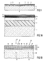
- a glass substrate (1) having a diameter of 5 inch was coated with a layer (2) of a photopolymerizable lacquer on the basis of acrylates.
- the uncured lacquer was applied between the substrate and the matrix.
- the surface of the matrix was provided with a negative of the desired guide track.
- the lacquer was cured by exposing it to UV-light through the substrate. Thereafter the matrix was removed. In this manner a guide track in the form of a groove (3) was made.
- the track is provided with control information constituted by optically readable information bits which are alternately located at a higher level(4) and a lower level (5).
- the bits are read in reflection with the aid of a weak laser light beam, not shown, on the basis of phase differences in the reflected light originating from a bit at a higher level and a lower level.
- Layer (2) was coated by a sputtering method with a dielecric layer (6) consisting of AlN having a thickness of 80 nm.
- a magneto-optical layer (7) in the form of a multi-layer was vapour deposited on top of the dielectric layer.
- the substrate (1) provided with layers (2) and (6) was placed in a belljar, which was thereafter evacuated to a pressure of 4.10 ⁇ 8 mbar.
- Co-layers having a thickness of 0.24 nm and Pt-layers having a thickness of 1.74 nm were successively e-beam evaporation deposited.
- the layers are shown in Fig. 1A, the Co-layers being denoted by 7a and the Pt-layers by 7b.
- the presssure was kept at 5.10 ⁇ 7 mbar.
- the deposition rates of the Pt and Co-metal sources was kept constant at a rate between 0.1-0.2 nm/s with the aid of quartz oscillators.
- the metal vapour flows were controlled by shutters.
- the overall thickness of the multi-layer was approximately 50 nm.
- the total number of Pt and Co-layers was 50 in this case.
- a reflection layer 7c of metal for example Al, Ag, Au, Ti, Cu or Pt having a thickness of 30 nm was evaporated on the recording layer, thus forming together with the multi-layer 79, 76 and the dielectric layer 6 a "tri-layer" structure.
- a second dielectric layer not shown in Fig. 1 and 1A was applied between the multi-layer and the reflection layer, so as to achieve a "quadri-layer" structure.
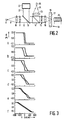
- Fig. 2 shows an arrangement for thermomagnetically recording and optically reading information in which the above-desscribed recording element is used.
- reference numeral 8 denotes an AlGaAs laser which produces a pulsed light beam 9 having a wavelength of 820 nm.
- the light beam is pulsed (modulated) in accordance with the information to be recorded.
- the light beam 9 passes through an objective 10 having a numerical aperture (NA) of 0.3.
- NA numerical aperture
- the astigmatism of the laser beam is corrected by passing it through a cylindrical lens 11.
- the parallel beam 12 thereafter passes through a partially transparent mirror 13 and a polarization splitter-cube 14 which transmits the parallel polarization component of the laser light, whilst the perpendicular commponent is reflected.
- the transmitted, linearly polarized light passes a Faraday rotator 15 which shifts the polarization direction through a small angle.
- the linearly polarized light is focussed by means of an objective 16 having a numerical aperture (NA) of 0.6 onto the recording layer 17 of the magneto-optical recording element 18.
- NA numerical aperture
- the recording layer 17 is a multi-layer formed by alternately stacked Co and Pt-layers, provided on a glass substrate 19. Exposure to light of the recording layer is effected via said substrate 19. In the exposed places a temperature increase to approximately the Curie point is effected by light absorption.
- a magnetic field having a force of 2 x 10⁴ A/m generated by coil 20 the magnetization direction of the recording layer is rotated in an exposed place through 180 o , thus forming an information bit with a reversed direction of magnetization.
- FIG. 1B The recording of information is further illustrated in Fig. 1B.
- reference numeral 30 denotes a dielectric layer, applied on a glass substrate (not shown).
- Layer 30 is provided with a multi-layer 31.
- layer 30 is provided with a vapour-deposited layer of Co (32), Pt (33), Co (34) and Pt (35).
- the multi-layer 31 is exposed to modulated laser light via the layer 30, as is shown by means of the arrows 42.
- an exposed spot 37 located between the broken line boundary faces 38, 39 the temperature of the multi-layer increases to the Curie point (approximately 700 K). This also occurs in the exposed spot 36, between the boundary facses 40 and 41.
- the direction of magnetization of the multi-layer is denoted by arrows 44 in the magnetic Co-layers 32 and 34.
- An external magnetic field whose direction is indicated by arrow 43 and whose magnitude is 2.104 A/m is applied across the plate.
- the direction of magnetization is reversed in response to the magnetic field 43. This is denoted by arrows 45 in the magnetic Co-layers 32 and 34.
- Reading the stored information is further illustrated with reference to Fig. 2.
- a continuous light beam, weak in energy, coming from the AlGaAs laser 8 travels along the same light path as described in the foregoing for the write beam 9, 12.
- the polariszation plane is rotated through an angle ⁇ k (Kerr rotation) in response to the locally changed magnetization direction.
- the reflected read light beam again passes through objective 16, the Faraday rotator 15 and then arrives at the polarization splitter cubes 14 wherein the parallel component is transmitted.
- the parallel component 21 is applied to the control arrangement 22 for positioning and focussing of the laser llight beam onto the recording layer 17 in the writing process.
- the perpendicular light component 24 of the read beam is reflected by the polarization splitter cube. Via an objective 23 the perpencidular component 24 is focussed onto and collected in a detector 25, constituted by, for example, an avalanche photodiode, so as to detect the Kerr rotation.
- a detector 25 constituted by, for example, an avalanche photodiode, so as to detect the Kerr rotation.
- a Table I shows results of optical and magnetical measurements on six recording elements.
- the column 1 denoted by R shows the test reference number.
- Column 2 shows the number L of bilayers each consisting of one magnetical and a non-magnetical layer, of the multi-layer.
- Column 3 shows the thickness t (nm) of the individual Co and Pt layers.
- Column 4 shows the Kerr rotation ( ⁇ k ) at 820 nm of the multi-layer.
- Column 5 shows the anisotropy energy K eff (kJ) per unit of volume Co.
- Column 6 shows the remanence (M r /M s ) expressed as a percentage
- column 7 shows the coercive force H c (kA/m).
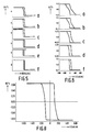
- c Fig. 4 shows the curves of the polar Kerr rotation ⁇ ( o ) as a function of the wavelength ⁇ (nm) of the examples listed in Table I. This Figure clearly shows that the polar Kerr rotation of the multi-layers increases when laser light with a relatively short wavelength is used. This indicates that the read-out of the multi-layers according to the present invention increases in the so-called blue- region of the spectrum, which makes the present multilayer especially interesting in combination with the so-called blue-laser.
- Table II shows a number of optical and magnetic properties of further multi-layers for use in a magneto-optical recording element. Also this Table shows that 100% remanence is obtained if the thickness of the Co-layers is less than 0.6 nm.
- Table II R L tCo tPt ⁇ k Mr/Ms Hc 7 35 0.31 1.30 -0.10 100 88 8 30 0.30 1.55 -0.08 100 100 9 30 0.31 1.74 -0.07 100 100 10 25 0.32 1.90 -0.07 100 80 11 30 0.40 1.27 -0.12 100 100 12 30 0.39 1.49 -0.11 100 112 13 25 0.41 1.71 -0.09 100 100 14 30 0.41 1.98 -0.07 100 100 15 30 0.62 1.32 -0.13 28 88 16 25 0.62 1.43 -0.12 30 65 17 25 0.62 1.63 -0.11 47 88 18 22 0.62 1.98 -0.10 66 88 19 50 0.45 0.58 -0.29 11 50 20 40 0.40 0.92 -0.2
- FIG. 5 shows the magneto-optical hysteresis loops measured at a wavelength ⁇ of 530 nm of a number of recording elements having recording layers in the form of multi-layers, the thickness of the Co-layers being 0.4 nm, and the thickness of the Pt-layers being 1.8 nm.
- the overall thickness of the recording layer is varied with values decreasing from 55 nm (curve a), 44 nm (curve b), 33 nm (curve c), 20 nm (curve d), 11 nm (curve e) to 6.6 nm (curve f).
- This Figure shows that the best hysteresis loops are obtained if the thickness of the overall multi-layer is less than approximately 40 nm.
- Fig. 6 shows the magneto-optical hysteresis loops measured at a wavelength of 530 nm of a number of recording layers in the form of multi-layers, the thickness of the Co-layers being 0.4 nm, and the thickness of the Pt-layers being 0.9 nm.
- the thickness of the total recording layer is varied by values decreasing from 52 nm (curve a), 40.3 nm (curve b), 30 nm (curve c), 20 nm (curve d) to 10 nm (curve e).
- This Figure shows that the remanance in a percentage figure of the multi-layer is optimal if the overall thickness of these layers is less than approximately 40 nm.
- Figs. 5 and 6 From measurements at the multi-layers illustrated in Figs. 5 and 6 it is also derived that the overall thickness of the layers must preferably be greater than 10 nm. At a smaller thickness the coercive force of the layers was found to decrease very rapidly.
- g Fig. 7 shows the polar Kerr rotation as a function of the wavelength of a recording layer (a) described in the preceding paragraph and of a recording layer of a comparable thickness on the basis of the known GdTbFe-material (b).
- the Kerr rotation of the recording material used in accordance with the invention is significantly greater at shorter wavelengths than the rotation of the prior-art material.
- a glass substrate was provided with a 70 nm thick dielectric layer of AlN, onto which thereafter a 18 nm thick recording layer was deposited, which was formed from 0.4 nm thick Co-layers and 1.8 nm thick Pt-layers.
- the multi-layer was coated with a 90 nm thick dielectric AlN layer on which a 30 nm thick reflection layer of Al was applied.
- a glass substrate with a 2-P lacquer was provided with a 80 nm thick dielectric layer of AlN, onto which thereafter a 23 nm thick recording layer was deposited, by means of e-beam evaporation, which layer was formed from 0.4 nm thick Co-layers and 0.9 nm thick Pt-layers.
- the first and the last layer of the multilayer consisted of Pt, so that all the Co-layers were sandwiched between Pt-layers. Contrary to example 4, no dielectric and reflection layer were deposited on the recording layer.
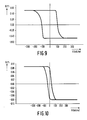
- Figure 8 shows the Kerr-hysteresis loop of the multilayer as measured through the glass substrate at a wavelength of 820 nm.
- the H c -value was 112 kA/m.
- Visual observation through a polarisation microscope proved that the stored domains (size approximately 1 ⁇ 2) were of a substantially perfect shape.
- the signal-to-noise ratio measured in these experiments was 53.0 dB.
- the disc noise was better than 9.3 dB.
- the write noise was 0.6 dB.
- a glass substrate with a 2-P lacquer was provided with a 80 nm thick dielectric layer of AlN, onto which thereafter a 23 nm thick recording layer was deposited by means of e-beam evaporation, which layer was formed from 0.4 nm thick Co-layers and 0.9 thick Pd-(paladium)layers.
- Figure 9 shows the Kerr-hysteresis loop of the multilayer as measured through the glass substrate at a wavelength of 820 nm.
- the H c -value is 107 kA/m.
- the signal-to-noises ratio was better than 50.5 dB.
- the disc noise was better than 8.7 dB.
- the write noise was 1.0 dB.
- a glass substrate was provided with a 64.4 nm thick recording layer by means of e-beam evaporation, which layer was formed from 0.5 nm thick Co-layers and 2.3 nm thick Au-layers.
- Figure 10 shows the Kerr-hysteresis loop of the multilayer as measured through the glass substrate at a wavelength of 530 nm.
- the H c -value is 38.4 kA/m and the remanence amounts 94%.
Abstract
Description
- Thermomagnetic recording of information and optically readable recording elements used therein.
- Thermomagnetic recording of information is a recording method which is known per se and is disclosed in, for example, Philips Techn. Rev. 42 , No. 2, pp. 51-58 (1985). In this method a recording element is used which has a substrate and a recording layer provided thereon. In the thermomagnetic recording of information, the thermomagnetic recording element is exposed to laser light originating from, for example, an AlGaAs layer having a wavelength of approximately 820 nm The laser light beam is focussed onto the recording layer by means of a lens system. The thermomagnetic recording layer includes a magnetic recording material having a perpendicular anisotropy in which the easy axis of magnetization is perpendicular to the layer surface. In the locations exposed to the laser light beam the temperature of the magnetic material increases and subsequently the direction of magnetization of the heated area is reversed. This reverse can take place spontaneously in response to interaction with the magnetic field of the adjacent magnetic material. Preferably, the direction of magnetization is reversed by means of an external magnetic field whose field direction is opposite to the direction of magnetization of the recording layer. After exposure the magnetic material cools and the changed direction of magnetization is fixed. The areas having the opposite direction of magnetization are representative of the recorded information. This information can be read with the aid of polarized laser light, on the basis of a rotation of the polarisation plane. This rotation is known as the Kerr-effect in the case of reflection and as the Faraday effect in the case of transmission of polarised light.
- So far two classes of magnetic materials in which thermomagnetic recording of information is possible are known. It should be noted that many magnetic materials are known which evidence said perpendicular anisotropy. However, only a few of these magnetic materials, belonging to said two classes, were found to be suitable for thermomagnetic recording.
- This is not very surprising since for thermomagnetic recording the material must satisfy very severe requirements. In addition, these requirements are often opposite natures, that is to say that satisfying one required property means that satisfying the other required property is more difficult. The various requirements the thermomagnetic recording material is to satisfy is that the material
- a) has a perpendicular magnetic anisotropy
- b) has a rectangular BH curve (i.e. a remanence of 100%) with a high coercive force at ambient temperature. The Hc-value of the thermomagnetic recording material must be larger than the writing field, i.e. larger than 40 kA/m,
- c) has a high magneto-optical figure of merit, Rϑ², wherein R represents the reflectivity and ϑ the rotation of the polarization plane of light on interaction with the recording material,
- d) has a relatively low Curie point Tc,
- e) has a good switching characteristic. As a result thereof, switching can be effected at different powers of the write laser and at minimal strength of the (external) magnetic field used, which strengths are preferably less than 40 kA/m,
- f) has a low disc noise and write noise,
- g) must be properly workable at low temperature, and
- h) must have an appropriate physical and chemical stability.
- The two classes of materials which reasonably satisfy said requirements are:
- 1. the class of amorphous rare earth material and transition metal alloys such as those described in inter alia Appl. Phys. Lett. 22 337 (1987).
Well-known and properly efficient materials of this class are, for example, GdTbFe or TbFeCo. - 2. the class of the oxidic compounds. In this class a further distinction can be made between (mono)crystalline garnets and ferrites. The thermomagnetic recording with the aid of monocrystalline garnet layers is disclosed in, inter alia ,J. Appl. Phys. 36 1110 (1965). The use of ferrites is described in the United States Patent US 4,586,092.
- The use of the prior-art thermomagnetic recording materials of the classes mentioned above has the following disadvantages.
- The ferrites have the drawback that the noise introduced by this material is relatively high. This causes a low signal-to-noise ratio (CNR), so that these materials are not so suitable for the recording of, for example, video (image) signals. A further drawback is that the ferrite layers must be processed into a recording layer at an elevated temperature. Thus, these materials are deposited on a substrate by, for example, sputter deposition 400-500oC. This means that the substrate must be capable of withstanding such high temperatures. It is therefore not very well possible to use a synthetic resin substrate or a substrate coated with a synthetic material layer. But it is precisely the use of a synthetic resin substrate or a substrate coated with a synthetic resin layer which is of great practical importance. It is, namely, possible to form a guide track, for example in the shape of a helical groove, in a simple and cheap manner in such a synthetic resin. By means of the guide track the laser light beam at the writing or reading process can be guided and controlled.
- The (mono)crystalline, rare earth metal containing garnets have the disadvantage that their production is very expensive. In practice, monocrystalline layers of this type are not or only little suitable for thermomagnetic recording and actually are only suitable for special , professional applications. The substrate onto which such a monocrystalline layer is provided must be a non-magnetical, monocrystalline garnet material. Also in this case there is the above-mentioned drawback, namely that the use of substrates containing a synthetic resin material is excluded. In addition, these materials have the disadvantage that they have a very high transmission, so that the coupling-in of the write laser light, i.e. the energy transfer, is very low.
- The thermomagnetic recording layers on the basis of GdTbFe or TbFeCo which upto now have proved to be the most promising layers, have the important disadvantage of a strong corrosion (oxidation) sensitivity. As a result thereof the layers are no longer suitable for recording after a short period of time and, in additon, the information already stored is lost. To obviate this drawback it has been proposed to use protective layers. However, this obviates the corrosion problem only partly. Moreover, this additionally complicates the structure of the recording element which consequently becomes more expensive.
- A further disadvantage of the use of rare earth metal and transition metal alloys in the thermomagnetic recording of information is the magnitude of the magneto-optical effect of this material. Magneto-optical effect must here be understood to mean the rotation of the polarization plane of the polarized laser light used on read-out. As will be described in detail hereinafter, the magnitude of this effect plays an essential role during the read-out of thermomagnetically recorded information. It has been found that the magnitude of this effect unfortunately reduces at shorter wavelengths of the read laser light, more specifically for wavelengths shorter than the read wavelength of 820 nm which at present is the mostly used read wavelength. Now, when short-wave laser light could be used, for example produced by what is commonly denoted a blue laser, then writing and/or reading could be effected with a higher information desnsity.
- The invention provides a method of thermomagnetic recording of information and the optical read-out of the stored information, which does not have the disadvantages and problems described sub c).
- The invention relates more specifically to a method of thermomagnetic recording of information and optical read-out of the stored information, in which a recording element being is used which has a substrate and a recording layer in the form of a multi-layer provided thereon, which comprises a plurality of magnetic, predominantly Co-containing layers of thickness of not more than 1.2 nm per layer and also a plurality of non-magnetic layers, each including at least one transition element and each having a thickness of not more than 2.4 nm, wherein magnetic and non-magnetic layers have been applied alternately and the overall thickness of the multi-layer is not more than 75 nm, the multi-layer in addition having an easy axis of magnetization which is perpendicular to the substrate surface, the multi-layer locally is exposed to a laser beam so that in these locations the temperature of the multi-layer is increased, the direction of magnetization of the exposed locations is reversed and the locations with the reversed magnetization which constitute the information bits are read out by polarized laser light on the basis of the rotation of the polarization plane.
- The recording element used in the method of the invention has a recording layer which is of a new type for thermomagnetic recording . As will be described in greater detail hereinafter, the class of multi-layer materials used here has a number of properties which are comparable to or considerably better than those of the prior art recording layers, which are based on the two known, above-defined classes of thermomagnetic recording materials. It should be noted that "predominantly containing Co" is to be understood that the magnetic layers have at least 90 at.% of Co. It is noted however, that some interdiffusion of the Co and the non-magnetic transition elements can occur at the boundaries of the magnetic layers and the non-magnetic layers. In that case, a lower amount of Co can be found in the magnetic layers, especially when the Co-layers are thinner than 0.6 nm. it should also be noted that "transition elements" are here to be understood to be elements from the columns VIII and I-B of the periodical system having an atomic number exceeding 44, such as more specifically Pt, Pd, Au, Rh and Ir.
- The recording layer in the form of a multy-layer, used in the thermomagnetic recording method of the invention, is chemically and physically very stable. In particular, no corrosion problems occur with this recording multi-layer, so that the recording elements are usable for a long period of time and the thermomagnetically stored information does not get lost. Repeated write tests have demonstrated that the direction of magnetization of the magnetic domains of the recording material can be changed at least a thousand times without chemical and/or structural changes being observable in the recording multi-layer.
- The magneto-optical effet of the thermomagnetic recording layers used in accordance with the invention, is sufficiently high so that a high signal-to-noise ratio of, for example, 50 dB or more can be achieved at a bandwidth of 30 kHz, a carrier of 1 MHz and a linear velocity of 5 m/s. Especially multilayers containing Pt and/or Pd as non-magnetic layers show such high values of the signal-to-noise ratio. With relatively short wavelengths of the read laser light this effect surprisingly increases still more and this effect is even considerably greater than the magneto-optical effect of the prior-art recording materials on the basis of GdTbFe. Measurements at 400 nm on a multi-layer formed by 0.5 nm thick Co-layers and 0.9 nm thick Pt-layers proved that this effect is approximately twice as high as with a GdTbFe recording material.
- The Curie point (Tc) of the recording elements used in the method of the invention is low, namely below 700 K. This is surprising since Co and the non-magnetic materials exist as separate layers. Thus one might have expected a rather high Tc, characteristic of Co-metal. The comparatively low Tc is very advantageous for the thermomagnetic writing process, since in this process the multi-layer is locally heated to near its Tc followed by a reversal of the direction of magnetization in these locations. For magnetic multi-layer having such a low Tc it was found in repeated write tests (1000 times) that the structure and the composition of the multi-layers is not or is hardly influenced by a temperature increase upto the Tc.
- The recording element used in the method according to the invention has in addition a high magneto-optical figure of merit, which is determined by the product R.ϑ², wherein R is the reflectivity and ϑ the Kerr-rotation of the multi-layer. The high value of the figure of merit provides a good impression of the advantageous use of the multi-layer of the present case for thermomagnetic recording. The value of the figure of merit is proportional to the signal-to-noise ratio achievable on read-out. An obtained high signal-to-noise ratio of, for example, 55 dB and higher enables the storage and read-out of video information.
- The coercive force at ambient temperature of the multi-layer used is relatively high, namely not less than 35 kA/m, and preferably not less than 80 kA/m. These high values of the coercive force ensure that the thermomagnetic domains have an adequate stability at ambient temperature.
- In addition, the recording element used has a perpendicular anisotropy. In experiments leading to the invention it was demonstrated that this is only the case if the thickness of the separate Co-layers is less than approximately 1.2 nm.
- It has further been found that the thickness of the recording layer of the recording element is of great importance. The overall thickness of the multy-layer must be less than 75 nm. It has been demonstrated that at a larger thickness a relatively fast heat dissipation in the multi-layer occurs during the thermomagnetic write procedure. Moreover, the heat capacity of a thin multilayer increases with increasing thickness. Consequently, the laser energy required for the writing operation becomes relatively high, which is a drawback for practical applications.
- The domains (or bits) written thermomagnetically in accordance with the method of the invention in the recording element are of a perfect shape. This is of great importance, as irregularities in the written domains produce the so-called write noise. It has been found that this type of noise gives generally an important contribution to the total noise. Because of the perfect shape of the domains (bits) the measured write noise of the recording element used is very low. It has been demonstrated that this write noise is less than the disc noise.
- In this connection it should be noted that writing the domains can be effected in different manners. In accordance with a first method, the recording element is held in a constant magnetic field which is directed oppositely to the direction of magnetization of the recording layer of the element. The information can be written-in by exposure of the recording layer to modulated laser light, the direction of magnetization being reversed in the exposed locations (laser modulation technique). In accordance with a second method an area of the recording layer of the element is exposed to a continuous laser light beam. In this heated region, with the aid of an external magnetic field which is modulated in conformity with the information to be stored, information bits with an opposite magnetization are written-in. The field direction is varied at a high velocity. This is denoted the field modulation technique. Both methods can be successfully applied in the method according to the invention. Generally, the field modulation technique has the advantage that information already present can directly be written-over, without the necessity of first erasing the recording layer. In addition, a further method can be used in which both the write laser and the magnetic field are modulated.
- In an advantageous embodiment of the method according to the invention, a recording element is used whose non-magnetic layers predominantly consist of Pt. Predominantly must here be understood to mean that these layers have a minimum of 90 at.% Pt. It has been found that because of the particularly high insensitivity to oxidation of such a recording element the stored information bits remain intact for a very long period of time. The elements which are least sensitive to oxidation are obtained by using non-magnetic layers which fully consist of Pt.
- In another advantageous embodiment of the method according to the invention, a recording element is used whose non-magnetic layers predominantly consist of Au. Predominantly must here be understood to mean that these layers have a minimum of 90 at.% Au. The corrosion resistance of such a recording element is excellent.
- In another advantageous embodiment of the method according to the invention, a recording element is used whose non-magnetic layers predominantly consist of Pd. Predominantly must here be understood to mean that these layers have a minimum of 90 at.% Pd. Apart from the excellent corrosion resistance such a recording element shows a high coercive force.
- In another advantageous embodiment of the method according to the invention, a recording element is used whose Co-containing magnetic layers have a maximum thickness of 0.6 nm. It has been found that if such a recording element is used, the recording layer has a remanence of 100% (Mr/Ms=1). This is of specific importance to provide an optimum switching characteristic.
- In accordance with a further preferred embodiment a recording element is used whose multi-layer has an overall thickness of not more than 40 nm. It has been demonstrated that this thickness approximately corresponds to the penetration depth of the laser light used (laser energy ∼15 mW).
- In another interesting embodiment of the recording element used in the method of the invention, the total thickness M of the magnetic layers and the total thickness N of the non-magnetic layers are defined by the
formula 1<N/M<5. Calculations and experiments resulting in the present invention have shown that very good write and read properties are obtained in the method according to the invention when the thicknesses of the magnetic and the non-magnetic layers of the multi-layer are chosen such that they satisfy this condition. It has been found in particular that if N/M is chosen to be less than 1, the remanence of the recording layer is relatively low. If N/M is chosen to be higher than 5, the Kerr-rotation appears to be relatively small. - A further interesting embodiment is characterized, in that a recording element is used in which the thickness of the individual Co-containing layers amounts to 0.3-0.5 nm, and the thickness of the individual Pt- or Pd-containing layers amounts to 0.8-1.2 nm. In this embodiment a high Kerr rotation is obtained in combination with a high remanence.
- The invention also relates to a recording element suitable for use in the method according to the invention. More specifically, the invention relates to a recording element having a substrate, and a recording layer applied thereon in the form of a multi-layer, which comprises a plurality of magnetic, predominantly Co-containing layers with a maximum thickness of 1.2 nm per layer, and also a plurality of non-magnetic layers, which each include at least one transition element and have a maximum thickness of 2.4 nm per layer, the magnetic and the non-magnetic layers are situated alternately, wherein the maximum thickness of the multi-layer is not more than 75 nm and in which the multi-layer has an easy axis of magnetization which is perpendicular to the substrate surface.
- It should be noted that the European Patent Application EP-A 241.080 discloses a magnetic recording element having a multi-layer of alternately applied Co-layers and Pd-layers. Information is written therein magnetically, so by using a magnetic head, the direction of magnetization being locally reversed under the influence of the magnetic field of the magnetic head. The overall thickness of the multi-layers described in said Patent Application exceeds 190 nm.
- In the recording element according to the invention the information is preferably written and read via the substrate. In that case the substrate must be transparent to the laser beam used. In this form of recording and reading it is achieved that any dust particles or any other contaminations on the surface of the substrate do not negatively affect the write or read quality, as they are outside the depth of focus of the objective by means of which the light beam is focussed onto the recording layer. The transparent substrate is made of, for example, glass, quartz or a transparent synthetic material, such as, for example, polycarbonate or polymethyl methacrylate.
- At the side facing the recording layer the surface of the substrate is preferably provided with an optically scannable guide track, in the form of, for example, a groove which usually is of helical or a circular shape. This groove may partly be provided with optically readable information bits, which control, for example, the write and read procedure. The optically readable bits are alternately located at a higher and a lower level, which causes the track thus obtained to have a crenelated shape. The information bits are read in reflection on the basis of phase differences in the reflected light. Magneto-optical recording can be effected in both the groove and at the dike portions located between the groove turns.
- When a glass substrate is used, the track is preferably made in a separate synthetic resin material layer provided on the substrate and consisting of, for example, light-cured acrylic esters. The recording layer is then applied on top of this layer.
- The recording layer may further be covered by a protection coating, for example a layer consisting of a light-cured lacquer, made of, for example, acrylic esters. An interesting feature is the possibility to glue or cement two recording elements of the invention to each other, the recording layers of the two elements then facing each other.
- In an interesting embodiment of the recording element according to the invention a dielectric layer is situated between the recording layer and the substrate.
- The dielectric layer contains, for example, an inorganic oxide, nitride, selenide, etc. Examples of suitable layers are layers made of Si₃N₄, AlN, SiO, SiO₂, ZnO, Zn₃n₂, ZnSi₃N₂, ZnSe, ZrO₂, TiO₂, and AlZrN₂. The use of such a layer results in a higher figure of merit.
- It should be noted that in the prior-art thermomagnetic recording elements in which, for example, GdTbFe is used, the choice of the dielectric layer is limited to oxygen-free materials in view of the sensitivity to oxidation. This does not hold for the thermomagnetic recording element in accordance with the invention.
- A further recording element in accordance with the invention which can be used with great advantage, is characterized, in that a reflection layer is present at that side of the recording layer remote from the substrate. Such an element can only be written in and be read via the substrate. On reading, the read laser beam passes the recording layer twice. Compared with a recording element without reflection layer, an element with a reflection layer has the particular advantage that the Kerr rotation of the detected read-out beam is under certain circumstances significantly increased. This effect strongly depends on the material of the reflection layer and the thickness of the multilayer. For instance, the application of a reflection layer of Al on a 40-50 nm thick recording layer provides an important increase in the signal-to-noise ratio. The reflection layer is usually constitued by a vapour-deposited or sputtered metal mirror. Suitable metals for this mirror are Al, Au, Ag, Pt, Cu and Ti.
- In a further advantageous embodiment of the recording element in accordance with the invention, a dielectric layer is provided between the recording layer and the reflection layer. This dielectric layer preferably contains the same material as the dielectric layer described in the foregoing, which is applied between the substrate and the recording layer. The use of this dielectric layer has the advantage that the figure of merit of the recording element is still further improved thereby and consequently a still better signal-to-noise ratio can be realized. Applying such a second dielectric layer is only advantageous for thin recording layers, for example thinner than 40 nm. Preferably, the recording layer then has a thickness of 10-25 nm.
- A still further interesting embodiment is the embodiment of the recording element according to the invention in which the recording element contains at least two recording layers each formed by a multi-layer, the recording layers being magnetically non-coupled and the recording layers being mutually separated by a spacer layer and in which the thickness of at least one of the recording layers is less than 40 nm. In practice it has been found that the recording layer can be very thin, the thermomagnetic and magneto-optical properties remaining adequate. Such thin layers are necessary in multi-layer systems, because the layer or layers in a more exterior position must be written or read via the layer or layers located more inwardly. Consequently, the layer or layers in a more interior position must still have some degree of transparency relative to the laser light used so as to reach the more exteriorly located layer. For this reason the more interiorly located layers must be thinner than 40 nm, more specifically preferably 10-30 nm thick. In this connection it should be noted that with the prior-art thermomagnetic recording materials on the basis of alloys of amorphous rare earth metal and transition metal a multi-layer recording element is not possible. The sensitivity to oxidation of this known material is so high that thin layers do not have an adequate lifetime.
- A particularly advantageous case is that in which the spacer layer contains an organic polymer, preferably a photopolymerized lacquer, for example on the basis of acrylic esters.
- Of special importance is also the embodiment of the recording element in which the multi-layer recording layer is composed of a write sector and a parallel extending read sector both having a plurality of magnetic and non-magnetic layers, the thickness (M) of the individual magnetic layers and the thickness (N) of individual non-magnetic layers being chosen such that it holds that: (N/M) read sector <(N/M) write sector. The use of multi-layer recording layers in recording elements renders it possible to separate the read function and the recording function in the recording layer in a simple manner and to optimize them separately. This is realized by increasing the Kerr rotation in the sector of the multi-layer where the read procedure is mainly effected (read sector). Such increase is achieved by increasing the relative thickness of the magnetic layers in this sector. In the other sector, in which the thermomagnetic write procedure is mainly effected (write sector), the thickness of the individual magnetic and non-magnetic layers must be chosen such that the properties of the multi-layer there are optimally suitable for thermomagnetic recording. In practice it has been found that this implies that the Co-content of the read sector exceeds the Co-content of the write-sector.
- It preferably holds for such a recording element that the overall thickness of the read sector and the overall thickness of the recording sector are in a ratio of 1 : 3. It further holds that it is advantageous for such a recording element to have the characterizing feature that (N/M) read sector = 3/2 and that (N/M) recording sector = 9/4.
- Interesting is also an embodiment of a recording element in which the non-magnetic layers of the read-sector contain essentially Pt and in which the non-magnetic layers of the write sector contain essentially Pd. This embodiment allows a further optimalisation of the recording requirements and the read-out requirements within a single recording multilayer.
- The multi-layer used in the recording element can be obtained in known manner by means of physical vapour deposition of the individual magnetic and non-magnetic layers. It has been found that depositon by means of vacuum vapour deposition, f.i. e-beam evaporation, has the advantage that the deposited multilayers show higher Hc- values than those obtained by sputtering. This holds particularly for Co-Pt multilayers. It is supposed that with evaporation metal layers are obtained with sharper transistions between the different metal layers than obtained by sputtering, because of the lower kinetic energy of the metal atoms impinging upon the surface, leading to less interdiffusion of the metal atoms.
- The thickness of the layers can be realized in a manner known per se by influencing the temperature of the metal sources and/or the deposition time of the individual elements.
- An interesting element is also a recording element having a magnetic recording layer constituted by a multi-layer which is magnetically exchange-coupled to a second magnetic recording layer of the element. The second recording layer may also be formed by a multi-layer, or consist of a known recording material, for example on the basis of GdTbFe or TbCoFe. As is described in inter alia the European Patent Application No. 258.978, recording elements of that type offer interesting possibilities for use in thermomagnetic recording methods of the type known as "direc overwrite". The use of at least one multi-layer in this record method has the advantage that the total layer thickness can be very limited, so that the write leaser energy required is small. In addition, exchange-coupled thin layers, having, for example a thickness less than 30 nm, but preferably less than 20 nm, have the advantage that this coupling occurs much more efficiently than with thicker layers.
- The invention will now be described in greater detail with reference to the embodiments shown in the accompanying drawing.
- A glass substrate (1) having a diameter of 5 inch (see Fig. 1) was coated with a layer (2) of a photopolymerizable lacquer on the basis of acrylates. The uncured lacquer was applied between the substrate and the matrix. The surface of the matrix was provided with a negative of the desired guide track. The lacquer was cured by exposing it to UV-light through the substrate. Thereafter the matrix was removed. In this manner a guide track in the form of a groove (3) was made. The track is provided with control information constituted by optically readable information bits which are alternately located at a higher level(4) and a lower level (5). The bits are read in reflection with the aid of a weak laser light beam, not shown, on the basis of phase differences in the reflected light originating from a bit at a higher level and a lower level. Layer (2) was coated by a sputtering method with a dielecric layer (6) consisting of AlN having a thickness of 80 nm. A magneto-optical layer (7) in the form of a multi-layer (see Fig. 1A) was vapour deposited on top of the dielectric layer. For that purpose the substrate (1) provided with layers (2) and (6) was placed in a belljar, which was thereafter evacuated to a pressure of 4.10⁻⁸ mbar. Co-layers having a thickness of 0.24 nm and Pt-layers having a thickness of 1.74 nm were successively e-beam evaporation deposited. The layers are shown in Fig. 1A, the Co-layers being denoted by 7a and the Pt-layers by 7b. During the deposition of the Co and the Pt the presssure was kept at 5.10⁻⁷ mbar. The deposition rates of the Pt and Co-metal sources was kept constant at a rate between 0.1-0.2 nm/s with the aid of quartz oscillators. The metal vapour flows were controlled by shutters. The overall thickness of the multi-layer was approximately 50 nm. The total number of Pt and Co-layers was 50 in this case. For the sake of clarity, only 10 layers are shown in Fig. 1A. In a number of cases a
reflection layer 7c of metal, for example Al, Ag, Au, Ti, Cu or Pt having a thickness of 30 nm was evaporated on the recording layer, thus forming together with the multi-layer 79, 76 and the dielectric layer 6 a "tri-layer" structure. In some cases a second dielectric layer, not shown in Fig. 1 and 1A was applied between the multi-layer and the reflection layer, so as to achieve a "quadri-layer" structure. - Fig. 2 shows an arrangement for thermomagnetically recording and optically reading information in which the above-desscribed recording element is used.
- In the Figure,
reference numeral 8 denotes an AlGaAs laser which produces a pulsed light beam 9 having a wavelength of 820 nm. The light beam is pulsed (modulated) in accordance with the information to be recorded. The light beam 9 passes through an objective 10 having a numerical aperture (NA) of 0.3. The astigmatism of the laser beam is corrected by passing it through acylindrical lens 11. Theparallel beam 12 thereafter passes through a partiallytransparent mirror 13 and a polarization splitter-cube 14 which transmits the parallel polarization component of the laser light, whilst the perpendicular commponent is reflected. The transmitted, linearly polarized light passes aFaraday rotator 15 which shifts the polarization direction through a small angle. Thereafter the linearly polarized light is focussed by means of an objective 16 having a numerical aperture (NA) of 0.6 onto therecording layer 17 of the magneto-optical recording element 18. This recording element is identical to the element shown in the Figs. 1 and 1A. Thus, therecording layer 17 is a multi-layer formed by alternately stacked Co and Pt-layers, provided on aglass substrate 19. Exposure to light of the recording layer is effected via saidsubstrate 19. In the exposed places a temperature increase to approximately the Curie point is effected by light absorption. By means of a magnetic field having a force of 2 x 10⁴ A/m generated by coil 20 the magnetization direction of the recording layer is rotated in an exposed place through 180o, thus forming an information bit with a reversed direction of magnetization. - The recording of information is further illustrated in Fig. 1B. In this Figure,
reference numeral 30 denotes a dielectric layer, applied on a glass substrate (not shown).Layer 30 is provided with a multi-layer 31. For the sake of clarity, only four sub-layers of multi-layer 31 are shown. Consequently,layer 30 is provided with a vapour-deposited layer of Co (32), Pt (33), Co (34) and Pt (35). The multi-layer 31 is exposed to modulated laser light via thelayer 30, as is shown by means of thearrows 42. In an exposedspot 37 located between the broken line boundary faces 38, 39 the temperature of the multi-layer increases to the Curie point (approximately 700 K). This also occurs in the exposedspot 36, between the boundary facses 40 and 41. The direction of magnetization of the multi-layer is denoted byarrows 44 in the magnetic Co-layers 32 and 34. An external magnetic field whose direction is indicated byarrow 43 and whose magnitude is 2.10⁴ A/m is applied across the plate. In the exposedspots magnetic field 43. This is denoted byarrows 45 in the magnetic Co-layers 32 and 34. - Reading the stored information is further illustrated with reference to Fig. 2. A continuous light beam, weak in energy, coming from the
AlGaAs laser 8 travels along the same light path as described in the foregoing for thewrite beam 9, 12. On reflection of the linearly polarized light beam against an information bit of therecording layer 17, the polariszation plane is rotated through an angle ϑk (Kerr rotation) in response to the locally changed magnetization direction. The reflected read light beam again passes through objective 16, theFaraday rotator 15 and then arrives at thepolarization splitter cubes 14 wherein the parallel component is transmitted. After reflection from the partiallytransparent mirror 13 theparallel component 21 is applied to thecontrol arrangement 22 for positioning and focussing of the laser llight beam onto therecording layer 17 in the writing process. The perpendicular light component 24 of the read beam is reflected by the polarization splitter cube. Via an objective 23 the perpencidular component 24 is focussed onto and collected in adetector 25, constituted by, for example, an avalanche photodiode, so as to detect the Kerr rotation. -
a Table I shows results of optical and magnetical measurements on six recording elements. Thecolumn 1 denoted by R shows the test reference number.Column 2 shows the number L of bilayers each consisting of one magnetical and a non-magnetical layer, of the multi-layer.Column 3 shows the thickness t (nm) of the individual Co and Pt layers.Column 4 shows the Kerr rotation (ϑk) at 820 nm of the multi-layer.Column 5 shows the anisotropy energy Keff (kJ) per unit of volume Co.Column 6 shows the remanence (Mr/Ms) expressed as a percentage, andcolumn 7 shows the coercive force Hc (kA/m). This Table clearly shows that the perpendicular anisotropy in the multi-layer is obtained when the thickness of the individual Co-layers is less than approximately 1.2 nm. Only then Keff is positive. In addition it is shown that a 100% remanence is obtained if the thickness of the individual Co-layers is less than approximately 0.6 nm.Table I R L tCo tPt ϑk Keff Mr /Ms Hc 1 25 0.24 1.74 -0.06 1074 100 44 2 22 0.45 1.77 -0.10 865 100 78 3 20 0.70 1.72 -0.12 475 40 52 4 19 0.92 1.74 -0.14 287 13 33 5 17 1.42 1.72 -0.18 -101 6 25 6 14 2.02 1.77 -0.25 -271 5 25
b Fig. 3 shows magneto-optical hysteresis loops of the embodiments listed in Table I in which the Kerr rotation is shown as a function of the applied field H. The loops a-f are measured at the respective test specimen 1-6. From the Figure it can also be derived that 100% remanence is obtained if the thickness of the individual Co-layers is less than approximately 0.6 nm.
c Fig. 4 shows the curves of the polar Kerr rotation ϑ(o) as a function of the wavelength λ (nm) of the examples listed in Table I. This Figure clearly shows that the polar Kerr rotation of the multi-layers increases when laser light with a relatively short wavelength is used. This indicates that the read-out of the multi-layers according to the present invention increases in the so-called blue- region of the spectrum, which makes the present multilayer especially interesting in combination with the so-called blue-laser.
d Table II shows a number of optical and magnetic properties of further multi-layers for use in a magneto-optical recording element. Also this Table shows that 100% remanence is obtained if the thickness of the Co-layers is less than 0.6 nm.Table II R L tCo tPt ϑk Mr/ Ms Hc 7 35 0.31 1.30 -0.10 100 88 8 30 0.30 1.55 -0.08 100 100 9 30 0.31 1.74 -0.07 100 100 10 25 0.32 1.90 -0.07 100 80 11 30 0.40 1.27 -0.12 100 100 12 30 0.39 1.49 -0.11 100 112 13 25 0.41 1.71 -0.09 100 100 14 30 0.41 1.98 -0.07 100 100 15 30 0.62 1.32 -0.13 28 88 16 25 0.62 1.43 -0.12 30 65 17 25 0.62 1.63 -0.11 47 88 18 22 0.62 1.98 -0.10 66 88 19 50 0.45 0.58 -0.29 11 50 20 40 0.40 0.92 -0.20 73 100
e Fig. 5 shows the magneto-optical hysteresis loops measured at a wavelength λ of 530 nm of a number of recording elements having recording layers in the form of multi-layers, the thickness of the Co-layers being 0.4 nm, and the thickness of the Pt-layers being 1.8 nm. The overall thickness of the recording layer is varied with values decreasing from 55 nm (curve a), 44 nm (curve b), 33 nm (curve c), 20 nm (curve d), 11 nm (curve e) to 6.6 nm (curve f). This Figure shows that the best hysteresis loops are obtained if the thickness of the overall multi-layer is less than approximately 40 nm.
f Fig. 6 shows the magneto-optical hysteresis loops measured at a wavelength of 530 nm of a number of recording layers in the form of multi-layers, the thickness of the Co-layers being 0.4 nm, and the thickness of the Pt-layers being 0.9 nm. The thickness of the total recording layer is varied by values decreasing from 52 nm (curve a), 40.3 nm (curve b), 30 nm (curve c), 20 nm (curve d) to 10 nm (curve e). This Figure shows that the remanance in a percentage figure of the multi-layer is optimal if the overall thickness of these layers is less than approximately 40 nm. From measurements at the multi-layers illustrated in Figs. 5 and 6 it is also derived that the overall thickness of the layers must preferably be greater than 10 nm. At a smaller thickness the coercive force of the layers was found to decrease very rapidly.
g Fig. 7 shows the polar Kerr rotation as a function of the wavelength of a recording layer (a) described in the preceding paragraph and of a recording layer of a comparable thickness on the basis of the known GdTbFe-material (b). The Kerr rotation of the recording material used in accordance with the invention is significantly greater at shorter wavelengths than the rotation of the prior-art material. - In a further embodiment a glass substrate was provided with a 70 nm thick dielectric layer of AlN, onto which thereafter a 18 nm thick recording layer was deposited, which was formed from 0.4 nm thick Co-layers and 1.8 nm thick Pt-layers. The multi-layer was coated with a 90 nm thick dielectric AlN layer on which a 30 nm thick reflection layer of Al was applied. In a number of thermomagnetical recording experiments (v = 1.4 m/s;
bandwidth 10 kHz f = 750 kHz; tp = 300 ns, Pwrite = 6 mW, Hwrite = 28 kAm) domains (bits) were stored in this recording element. Visual observation through a polarization microscope proved that the stored domains (size approximately 1µ²) were of a substantially perfect shape. The signal-to-noise ratio measured in these experiments was 42.4 dB. The disk noise was better than 15 dB. The write noise was so low that it could not be measured. From further experiments it had been derived that with an optimum composition of the recording layer a signal/noise ratio of 65 dB can be realised. - In another embodiment a glass substrate with a 2-P lacquer was provided with a 80 nm thick dielectric layer of AlN, onto which thereafter a 23 nm thick recording layer was deposited, by means of e-beam evaporation, which layer was formed from 0.4 nm thick Co-layers and 0.9 nm thick Pt-layers. The first and the last layer of the multilayer consisted of Pt, so that all the Co-layers were sandwiched between Pt-layers. Contrary to example 4, no dielectric and reflection layer were deposited on the recording layer.
- Figure 8 shows the Kerr-hysteresis loop of the multilayer as measured through the glass substrate at a wavelength of 820 nm. The Hc-value was 112 kA/m. In a number of thermomagnetical recording experiments (v = 5 m/s;
bandwidth 30 kHz; f = 1 MHz; tp = 400 ns, Pwrite = 8 mW, Hwrite = 48 kA/m) domains (bits) were stored in this recording element. Visual observation through a polarisation microscope proved that the stored domains (size approximately 1µ²) were of a substantially perfect shape. The signal-to-noise ratio measured in these experiments was 53.0 dB. The disc noise was better than 9.3 dB. The write noise was 0.6 dB. - In another embodiment a glass substrate with a 2-P lacquer was provided with a 80 nm thick dielectric layer of AlN, onto which thereafter a 23 nm thick recording layer was deposited by means of e-beam evaporation, which layer was formed from 0.4 nm thick Co-layers and 0.9 thick Pd-(paladium)layers.
- Figure 9 shows the Kerr-hysteresis loop of the multilayer as measured through the glass substrate at a wavelength of 820 nm. The Hc-value is 107 kA/m. In a number of thermomagnetical recording experiments (v = 5 m/s;
bandwidth 30 kHz; f = 1 MHz; tp = 400 ns; Pwrite = 9.2 mW; Hwrite = 40 kA/m) domains (bits) were stored in this recording element. The signal-to-noises ratio was better than 50.5 dB. The disc noise was better than 8.7 dB. The write noise was 1.0 dB. - In another embodiment a glass substrate was provided with a 64.4 nm thick recording layer by means of e-beam evaporation, which layer was formed from 0.5 nm thick Co-layers and 2.3 nm thick Au-layers.
- Figure 10 shows the Kerr-hysteresis loop of the multilayer as measured through the glass substrate at a wavelength of 530 nm. The Hc-value is 38.4 kA/m and the remanence amounts 94%.
- The drawing comprises 10 Figures, wherein
- Fig. 1 is a tangential cross-sectional view of a magneto-optical recording element according to the invention,
- Fig. 1A is a cross-sectional view taken on the line A-B of Fig. 1 of a magneto-optical element according to the invention,
- Fig. 1B is a cross-sectional view of the recording element of Fig. 1 and 1A, with reference to which the recording process is described,
- Fig. 2 is a schematic view of a recording arrangement in which the method according to the invention can be used,
- Fig. 3 shows the magneto-optical hysteresis loops of a number of recording layers in the form of a Co/Pt multi-layer,
- Fig. 4 shows the polar Kerr rotation as a function of the magnetic field applied of a number of recording layers in the form of a Co/Pt multi-layer,
- Fig. 5 shows the polar Kerr rotation as a function of the magnetic field applied of a number of recording layers of varying thicknesses in the form of a Co/Pt multi-layer,
- Fig. 6 shows the polar Kerr rotation as a function of the magnetic field applied of a number of further recording layers of varying thicknesses in the form of a Co/Pt multi-layer,
- Fig. 7 shows the polar Kerr rotation as a function of the wavelength of a recording layer in a recording element according to the invention and a recording layer on the basis of GdTbFe in a prior-art recording element,
- Fig. 8 shows the polar Kerr rotation as a function of the magnetic field applied of a registration element comprising a Co/Pt-multilayer.
- Fig. 9 shows the polar Kerr rotation as a funtion of the magnetic field applied of a registration element comprising a Co/Pd-multilayer.
- Fig. 10 shows the polar Kerr rotation as a function of the magnetic field applied of a registration element comprising a Co/Au-multilayer.
Claims (20)
Applications Claiming Priority (2)
| Application Number | Priority Date | Filing Date | Title |
|---|---|---|---|
| NL8803168A NL8803168A (en) | 1988-12-24 | 1988-12-24 | METHOD FOR THERMOMAGNETIC RECORDING OF INFORMATION AND OPTICAL READING OF THE REGISTERED INFORMATION AND A REGISTRATION ELEMENT SUITABLE FOR USE IN THIS PROCESS. |
| NL8803168 | 1988-12-24 |
Publications (2)
| Publication Number | Publication Date |
|---|---|
| EP0376375A1 true EP0376375A1 (en) | 1990-07-04 |
| EP0376375B1 EP0376375B1 (en) | 1995-03-15 |
Family
ID=19853439
Family Applications (1)
| Application Number | Title | Priority Date | Filing Date |
|---|---|---|---|
| EP89203214A Expired - Lifetime EP0376375B1 (en) | 1988-12-24 | 1989-12-18 | Method of thermomagnetic recording of information and optical read-out of the stored information, and also a recording element suitable for use in this method |
Country Status (11)
| Country | Link |
|---|---|
| US (1) | US5109375A (en) |
| EP (1) | EP0376375B1 (en) |
| JP (1) | JPH02263344A (en) |
| KR (1) | KR0168626B1 (en) |
| AT (1) | ATE120025T1 (en) |
| DE (1) | DE68921726T2 (en) |
| ES (1) | ES2072291T3 (en) |
| HU (1) | HUT55156A (en) |
| NL (1) | NL8803168A (en) |
| RU (1) | RU2040047C1 (en) |
| YU (1) | YU244689A (en) |
Cited By (9)
| Publication number | Priority date | Publication date | Assignee | Title |
|---|---|---|---|---|
| EP0492359A1 (en) * | 1990-12-20 | 1992-07-01 | Sony Corporation | Magneto-optical recording medium |
| EP0492584A2 (en) * | 1990-12-28 | 1992-07-01 | Sony Corporation | Magneto-optical recording medium |
| EP0515222A2 (en) * | 1991-05-23 | 1992-11-25 | Sharp Kabushiki Kaisha | Magneto-optical storage device |
| EP0529795A1 (en) * | 1991-07-22 | 1993-03-03 | Canon Kabushiki Kaisha | Magnetooptic recording medium |
| EP0530913A1 (en) * | 1991-09-03 | 1993-03-10 | Koninklijke Philips Electronics N.V. | Magneto-optical recording medium |
| US5305300A (en) * | 1991-02-13 | 1994-04-19 | Sharp Kabushiki Kaisha | Magneto optical storage device using a multi-layer film of Pt/Co laminated sections |
| EP0519949B1 (en) * | 1990-03-15 | 1995-11-08 | Mitsubishi Chemical Corporation | Platinum or palladium/cobalt multilayer on a zinc oxide or indium oxide layer for magneto-optical recording |
| EP0762412A1 (en) * | 1995-08-25 | 1997-03-12 | Eastman Kodak Company | Optical storage medium including multiple data levels made of Co/Pt magneto-optical recording media |
| AT413777B (en) * | 2001-03-21 | 2006-05-15 | Clearjet Gmbh | DEVICE FOR PROCESSING SHEET-MESSAGE INFORMATION CARRIER |
Families Citing this family (7)
| Publication number | Priority date | Publication date | Assignee | Title |
|---|---|---|---|---|
| US5346740A (en) * | 1990-09-25 | 1994-09-13 | Matsushita Electric Industrial Co., Ltd. | Optical information recording medium |
| EP0498657A3 (en) * | 1991-02-08 | 1993-03-03 | Canon Kabushiki Kaisha | Optical recording medium, method of reproducing recorded data of optical recording medium, and system for reproducing recorded data of optical recording medium |
| JPH0573990A (en) * | 1991-03-07 | 1993-03-26 | Hitachi Ltd | Optical recording method, optical recording and reproducing method, optical recording material and optical recording device |
| GB9216074D0 (en) * | 1992-07-28 | 1992-09-09 | Johnson Matthey Plc | Magneto-optical recording materials system |
| US6243350B1 (en) * | 1996-05-01 | 2001-06-05 | Terastor Corporation | Optical storage systems with flying optical heads for near-field recording and reading |
| EP1239307A1 (en) * | 2001-03-09 | 2002-09-11 | Sicpa Holding S.A. | Magnetic thin film interference device |
| US20020192506A1 (en) | 2001-06-04 | 2002-12-19 | International Business Machines Corporation | `Thermal Spring' magnetic recording media for writing using magnetic and thermal gradients |
Citations (1)
| Publication number | Priority date | Publication date | Assignee | Title |
|---|---|---|---|---|
| EP0304873A1 (en) * | 1987-08-26 | 1989-03-01 | Sony Corporation | Magneto-optical recording medium |
Family Cites Families (10)
| Publication number | Priority date | Publication date | Assignee | Title |
|---|---|---|---|---|
| JPS61117747A (en) * | 1984-11-12 | 1986-06-05 | Nippon Kogaku Kk <Nikon> | 2-layer-film optical magnetic recording medium |
| US4587176A (en) * | 1985-01-14 | 1986-05-06 | E. I. Du Pont De Nemours And Company | Layered coherent structures for magnetic recording |
| US4731300A (en) * | 1985-03-07 | 1988-03-15 | Victor Company Of Japan, Ltd. | Perpendicular magnetic recording medium and manufacturing method thereof |
| US4635076A (en) * | 1985-03-14 | 1987-01-06 | Minnesota Mining And Manufacturing Company | Two-sided optical recording medium |
| US4678721A (en) * | 1986-04-07 | 1987-07-07 | U.S. Philips Corporation | Magnetic recording medium |
| US4789606A (en) * | 1986-04-17 | 1988-12-06 | Fuji Photo Film Co., Ltd. | Magneto-optical recording medium |
| JPH0782674B2 (en) * | 1986-11-06 | 1995-09-06 | キヤノン株式会社 | Magneto-optical memory medium |
| DE3727093A1 (en) * | 1987-08-14 | 1989-02-23 | Basf Ag | AREA-SHAPED, MULTILAYERED, LASER-OPTICAL RECORDING MATERIAL |
| JPH01149246A (en) * | 1987-12-04 | 1989-06-12 | Sony Corp | Magneto-optical recording medium |
| EP0367685A3 (en) * | 1988-10-31 | 1991-08-07 | Eastman Kodak Company | Magnetooptical recording element |
-
1988
- 1988-12-24 NL NL8803168A patent/NL8803168A/en not_active Application Discontinuation
-
1989
- 1989-07-24 US US07/384,587 patent/US5109375A/en not_active Expired - Fee Related
- 1989-12-18 ES ES89203214T patent/ES2072291T3/en not_active Expired - Lifetime
- 1989-12-18 EP EP89203214A patent/EP0376375B1/en not_active Expired - Lifetime
- 1989-12-18 DE DE68921726T patent/DE68921726T2/en not_active Expired - Fee Related
- 1989-12-18 AT AT89203214T patent/ATE120025T1/en not_active IP Right Cessation
- 1989-12-20 HU HU896701A patent/HUT55156A/en unknown
- 1989-12-21 RU SU894742828A patent/RU2040047C1/en active
- 1989-12-22 JP JP1331397A patent/JPH02263344A/en active Pending
- 1989-12-22 KR KR1019890019217A patent/KR0168626B1/en not_active IP Right Cessation
- 1989-12-25 YU YU02446/89A patent/YU244689A/en unknown
Patent Citations (1)
| Publication number | Priority date | Publication date | Assignee | Title |
|---|---|---|---|---|
| EP0304873A1 (en) * | 1987-08-26 | 1989-03-01 | Sony Corporation | Magneto-optical recording medium |
Non-Patent Citations (2)
| Title |
|---|
| PATENT ABSTRACTS OF JAPAN vol. 12, no. 129 (P-692)(2976) 21 April 1988, & JP-A-62 252546 (FUJI PHOTO FILM CO., LTD.) 04 November 1987, * |
| PATENT ABSTRACTS OF JAPAN vol. 12, no. 417 (P-782)(3264) 07 November 1988, & JP-A-63 153749 (FUJITSU LTD.) 27 June 1988, * |
Cited By (14)
| Publication number | Priority date | Publication date | Assignee | Title |
|---|---|---|---|---|
| EP0519949B1 (en) * | 1990-03-15 | 1995-11-08 | Mitsubishi Chemical Corporation | Platinum or palladium/cobalt multilayer on a zinc oxide or indium oxide layer for magneto-optical recording |
| EP0492359A1 (en) * | 1990-12-20 | 1992-07-01 | Sony Corporation | Magneto-optical recording medium |
| EP0492584A3 (en) * | 1990-12-28 | 1993-03-17 | Sony Corporation | Magneto-optical recording medium |
| EP0492584A2 (en) * | 1990-12-28 | 1992-07-01 | Sony Corporation | Magneto-optical recording medium |
| US5958575A (en) * | 1990-12-28 | 1999-09-28 | Sony Corporation | Magneto-optical recording medium |
| US5305300A (en) * | 1991-02-13 | 1994-04-19 | Sharp Kabushiki Kaisha | Magneto optical storage device using a multi-layer film of Pt/Co laminated sections |
| EP0515222A3 (en) * | 1991-05-23 | 1993-02-24 | Sharp Kabushiki Kaisha | Magneto-optical storage device and manufacturing method thereof |
| EP0515222A2 (en) * | 1991-05-23 | 1992-11-25 | Sharp Kabushiki Kaisha | Magneto-optical storage device |
| EP0529795A1 (en) * | 1991-07-22 | 1993-03-03 | Canon Kabushiki Kaisha | Magnetooptic recording medium |
| US5370945A (en) * | 1991-07-22 | 1994-12-06 | Canon Kabushiki Kaisha | Magnetooptic recording medium |
| EP0530913A1 (en) * | 1991-09-03 | 1993-03-10 | Koninklijke Philips Electronics N.V. | Magneto-optical recording medium |
| US5952094A (en) * | 1991-09-03 | 1999-09-14 | U.S. Philips Corporation | Magneto-optical recording medium |
| EP0762412A1 (en) * | 1995-08-25 | 1997-03-12 | Eastman Kodak Company | Optical storage medium including multiple data levels made of Co/Pt magneto-optical recording media |
| AT413777B (en) * | 2001-03-21 | 2006-05-15 | Clearjet Gmbh | DEVICE FOR PROCESSING SHEET-MESSAGE INFORMATION CARRIER |
Also Published As
| Publication number | Publication date |
|---|---|
| DE68921726D1 (en) | 1995-04-20 |
| JPH02263344A (en) | 1990-10-26 |
| NL8803168A (en) | 1990-07-16 |
| DE68921726T2 (en) | 1995-09-14 |
| KR900010695A (en) | 1990-07-09 |
| EP0376375B1 (en) | 1995-03-15 |
| US5109375A (en) | 1992-04-28 |
| RU2040047C1 (en) | 1995-07-20 |
| YU244689A (en) | 1990-12-31 |
| HU896701D0 (en) | 1990-02-28 |
| HUT55156A (en) | 1991-04-29 |
| KR0168626B1 (en) | 1999-03-20 |
| ATE120025T1 (en) | 1995-04-15 |
| ES2072291T3 (en) | 1995-07-16 |
Similar Documents
| Publication | Publication Date | Title |
|---|---|---|
| CA1213670A (en) | Multi-layer amorphous optical recording medium | |
| EP0376375B1 (en) | Method of thermomagnetic recording of information and optical read-out of the stored information, and also a recording element suitable for use in this method | |
| CA1217859A (en) | Amorphous magneto optical recording medium | |
| US4753853A (en) | Double-layered magnetooptical recording medium | |
| EP0368194B1 (en) | Magneto-optical recording medium | |
| US4842956A (en) | Opto-magnetic recording medium having three exchange-coupled magnetic layers | |
| US4833043A (en) | Amorphous magneto optical recording medium | |
| EP1050877B1 (en) | Opto-magnetic recording medium and its manufacturing method, and opto-magnetic information recording/reproducing device | |
| US4684454A (en) | Sputtering process for making magneto optic alloy | |
| EP0333467B1 (en) | Optical magnetic recording medium provided with high coercive force layer and low coercive force layer containing light rare earth | |
| JPS61248231A (en) | Optical recording method and optical recording medium | |
| EP0530913B1 (en) | Magneto-optical recording medium | |
| JPS61248232A (en) | Optical recording method and optical recording medium | |
| US5612109A (en) | Optical storage medium including multiple data levels made of Co/Pt magneto-optic recording media | |
| EP0305666B1 (en) | Amorphous magneto optical recording medium | |
| US4721658A (en) | Amorphous magneto optical recording medium | |
| JPS6122455A (en) | Magnetooptic recording medium | |
| EP0239974A2 (en) | Magneto-optical recording medium | |
| JP3381960B2 (en) | Magneto-optical recording medium | |
| JP3148017B2 (en) | Magneto-optical recording medium and method of manufacturing the same | |
| JPH11126384A (en) | Magneto-optical record medium and its recording and reproducing method | |
| EP0762412A1 (en) | Optical storage medium including multiple data levels made of Co/Pt magneto-optical recording media | |
| JPH07302444A (en) | Magneto-optical recording medium | |
| JPS6189605A (en) | Metal oxide magnetic substance and magnetic film | |
| JPS6314344A (en) | Information recording medium |
Legal Events
| Date | Code | Title | Description |
|---|---|---|---|
| PUAI | Public reference made under article 153(3) epc to a published international application that has entered the european phase |
Free format text: ORIGINAL CODE: 0009012 |
|
| AK | Designated contracting states |
Kind code of ref document: A1 Designated state(s): AT BE CH DE ES FR GB IT LI LU NL SE |
|
| 17P | Request for examination filed |
Effective date: 19901219 |
|
| 17Q | First examination report despatched |
Effective date: 19930603 |
|
| GRAA | (expected) grant |
Free format text: ORIGINAL CODE: 0009210 |
|
| AK | Designated contracting states |
Kind code of ref document: B1 Designated state(s): AT BE CH DE ES FR GB IT LI LU NL SE |
|
| PG25 | Lapsed in a contracting state [announced via postgrant information from national office to epo] |
Ref country code: NL Free format text: LAPSE BECAUSE OF NON-PAYMENT OF DUE FEES Effective date: 19950315 Ref country code: LI Effective date: 19950315 Ref country code: CH Effective date: 19950315 Ref country code: BE Effective date: 19950315 Ref country code: AT Effective date: 19950315 |
|
| REF | Corresponds to: |
Ref document number: 120025 Country of ref document: AT Date of ref document: 19950415 Kind code of ref document: T |
|
| REF | Corresponds to: |
Ref document number: 68921726 Country of ref document: DE Date of ref document: 19950420 |
|
| ITF | It: translation for a ep patent filed |
Owner name: ING. C. GREGORJ S.P.A. |
|
| PG25 | Lapsed in a contracting state [announced via postgrant information from national office to epo] |
Ref country code: SE Effective date: 19950615 |
|
| ET | Fr: translation filed | ||
| REG | Reference to a national code |
Ref country code: CH Ref legal event code: PL |
|
| REG | Reference to a national code |
Ref country code: ES Ref legal event code: FG2A Ref document number: 2072291 Country of ref document: ES Kind code of ref document: T3 |
|
| NLV1 | Nl: lapsed or annulled due to failure to fulfill the requirements of art. 29p and 29m of the patents act | ||
| PG25 | Lapsed in a contracting state [announced via postgrant information from national office to epo] |
Ref country code: LU Free format text: LAPSE BECAUSE OF NON-PAYMENT OF DUE FEES Effective date: 19951231 |
|
| PLBE | No opposition filed within time limit |
Free format text: ORIGINAL CODE: 0009261 |
|
| STAA | Information on the status of an ep patent application or granted ep patent |
Free format text: STATUS: NO OPPOSITION FILED WITHIN TIME LIMIT |
|
| 26N | No opposition filed | ||
| REG | Reference to a national code |
Ref country code: FR Ref legal event code: CD |
|
| REG | Reference to a national code |
Ref country code: ES Ref legal event code: PC2A |
|
| PGFP | Annual fee paid to national office [announced via postgrant information from national office to epo] |
Ref country code: ES Payment date: 20001219 Year of fee payment: 12 |
|
| PGFP | Annual fee paid to national office [announced via postgrant information from national office to epo] |
Ref country code: GB Payment date: 20001220 Year of fee payment: 12 |
|
| PGFP | Annual fee paid to national office [announced via postgrant information from national office to epo] |
Ref country code: FR Payment date: 20001226 Year of fee payment: 12 |
|
| PGFP | Annual fee paid to national office [announced via postgrant information from national office to epo] |
Ref country code: DE Payment date: 20010214 Year of fee payment: 12 |
|
| PG25 | Lapsed in a contracting state [announced via postgrant information from national office to epo] |
Ref country code: GB Free format text: LAPSE BECAUSE OF NON-PAYMENT OF DUE FEES Effective date: 20011218 |
|
| REG | Reference to a national code |
Ref country code: GB Ref legal event code: IF02 |
|
| PG25 | Lapsed in a contracting state [announced via postgrant information from national office to epo] |
Ref country code: DE Free format text: LAPSE BECAUSE OF NON-PAYMENT OF DUE FEES Effective date: 20020702 |
|
| GBPC | Gb: european patent ceased through non-payment of renewal fee |
Effective date: 20011218 |
|
| PG25 | Lapsed in a contracting state [announced via postgrant information from national office to epo] |
Ref country code: FR Free format text: LAPSE BECAUSE OF NON-PAYMENT OF DUE FEES Effective date: 20020830 |
|
| REG | Reference to a national code |
Ref country code: FR Ref legal event code: ST |
|
| PG25 | Lapsed in a contracting state [announced via postgrant information from national office to epo] |
Ref country code: ES Free format text: LAPSE BECAUSE OF NON-PAYMENT OF DUE FEES Effective date: 20021219 |
|
| REG | Reference to a national code |
Ref country code: ES Ref legal event code: FD2A Effective date: 20030113 |
|
| PG25 | Lapsed in a contracting state [announced via postgrant information from national office to epo] |
Ref country code: IT Free format text: LAPSE BECAUSE OF NON-PAYMENT OF DUE FEES;WARNING: LAPSES OF ITALIAN PATENTS WITH EFFECTIVE DATE BEFORE 2007 MAY HAVE OCCURRED AT ANY TIME BEFORE 2007. THE CORRECT EFFECTIVE DATE MAY BE DIFFERENT FROM THE ONE RECORDED. Effective date: 20051218 |