EP0376056A2 - Optical multiplexed electrical distribution system particularly suited for vehicles - Google Patents
Optical multiplexed electrical distribution system particularly suited for vehicles Download PDFInfo
- Publication number
- EP0376056A2 EP0376056A2 EP89122994A EP89122994A EP0376056A2 EP 0376056 A2 EP0376056 A2 EP 0376056A2 EP 89122994 A EP89122994 A EP 89122994A EP 89122994 A EP89122994 A EP 89122994A EP 0376056 A2 EP0376056 A2 EP 0376056A2
- Authority
- EP
- European Patent Office
- Prior art keywords
- light
- buss
- control
- devices
- interfacing
- Prior art date
- Legal status (The legal status is an assumption and is not a legal conclusion. Google has not performed a legal analysis and makes no representation as to the accuracy of the status listed.)
- Granted
Links
- 230000003287 optical effect Effects 0.000 title claims abstract description 66
- 230000005540 biological transmission Effects 0.000 claims abstract description 10
- 230000005284 excitation Effects 0.000 claims abstract description 6
- 230000004044 response Effects 0.000 claims description 21
- 239000013307 optical fiber Substances 0.000 claims description 16
- 230000033001 locomotion Effects 0.000 claims description 12
- 230000006870 function Effects 0.000 claims description 11
- 239000003086 colorant Substances 0.000 claims description 7
- 230000004913 activation Effects 0.000 claims description 5
- 230000011664 signaling Effects 0.000 claims description 2
- 230000007246 mechanism Effects 0.000 claims 9
- 230000008878 coupling Effects 0.000 claims 2
- 238000010168 coupling process Methods 0.000 claims 2
- 238000005859 coupling reaction Methods 0.000 claims 2
- 238000009429 electrical wiring Methods 0.000 abstract description 4
- 239000000835 fiber Substances 0.000 description 27
- 238000010586 diagram Methods 0.000 description 13
- 238000005286 illumination Methods 0.000 description 4
- 241000407429 Maja Species 0.000 description 3
- 238000000034 method Methods 0.000 description 3
- 229910001507 metal halide Inorganic materials 0.000 description 2
- 150000005309 metal halides Chemical class 0.000 description 2
- 230000005693 optoelectronics Effects 0.000 description 2
- 238000001228 spectrum Methods 0.000 description 2
- XLYOFNOQVPJJNP-UHFFFAOYSA-N water Substances O XLYOFNOQVPJJNP-UHFFFAOYSA-N 0.000 description 2
- 101100181922 Caenorhabditis elegans lin-32 gene Proteins 0.000 description 1
- 241001417501 Lobotidae Species 0.000 description 1
- QAOWNCQODCNURD-UHFFFAOYSA-N Sulfuric acid Chemical compound OS(O)(=O)=O QAOWNCQODCNURD-UHFFFAOYSA-N 0.000 description 1
- 230000003213 activating effect Effects 0.000 description 1
- 238000004378 air conditioning Methods 0.000 description 1
- 238000003491 array Methods 0.000 description 1
- 230000008901 benefit Effects 0.000 description 1
- 230000001419 dependent effect Effects 0.000 description 1
- 238000001514 detection method Methods 0.000 description 1
- 239000012530 fluid Substances 0.000 description 1
- 230000000977 initiatory effect Effects 0.000 description 1
- QSHDDOUJBYECFT-UHFFFAOYSA-N mercury Chemical compound [Hg] QSHDDOUJBYECFT-UHFFFAOYSA-N 0.000 description 1
- 229910052753 mercury Inorganic materials 0.000 description 1
- 229910052751 metal Inorganic materials 0.000 description 1
- 239000002184 metal Substances 0.000 description 1
- 239000000203 mixture Substances 0.000 description 1
- 230000000737 periodic effect Effects 0.000 description 1
- 230000009467 reduction Effects 0.000 description 1
- 229910052724 xenon Inorganic materials 0.000 description 1
- FHNFHKCVQCLJFQ-UHFFFAOYSA-N xenon atom Chemical compound [Xe] FHNFHKCVQCLJFQ-UHFFFAOYSA-N 0.000 description 1
Images


Classifications
-
- B—PERFORMING OPERATIONS; TRANSPORTING
- B60—VEHICLES IN GENERAL
- B60R—VEHICLES, VEHICLE FITTINGS, OR VEHICLE PARTS, NOT OTHERWISE PROVIDED FOR
- B60R16/00—Electric or fluid circuits specially adapted for vehicles and not otherwise provided for; Arrangement of elements of electric or fluid circuits specially adapted for vehicles and not otherwise provided for
- B60R16/02—Electric or fluid circuits specially adapted for vehicles and not otherwise provided for; Arrangement of elements of electric or fluid circuits specially adapted for vehicles and not otherwise provided for electric constitutive elements
- B60R16/03—Electric or fluid circuits specially adapted for vehicles and not otherwise provided for; Arrangement of elements of electric or fluid circuits specially adapted for vehicles and not otherwise provided for electric constitutive elements for supply of electrical power to vehicle subsystems or for
- B60R16/0315—Electric or fluid circuits specially adapted for vehicles and not otherwise provided for; Arrangement of elements of electric or fluid circuits specially adapted for vehicles and not otherwise provided for electric constitutive elements for supply of electrical power to vehicle subsystems or for using multiplexing techniques
- B60R2016/0322—Temporary code for documents to be reclassified to G08C, H04L or H04Q
Definitions
- the present invention relates to an electrical distribution system for a vehicle, and more particularly, to an optical multiplexed distribution system that reduces the complexity of the electrical wiring harness of a vehicle.
- While the above two (2) disclosures provide light generating and distribution systems for a vehicle, there still remains a need to reduce the complexity of the light generating and distribution system, along with the overall electrical distribution system, in particular, the wiring harness related to the electrical needs of the vehicle.
- Some of the problems that create the complexity of the electrical distribution system of a vehicle is that the switches for illuminating or motorizing devices that may be activated by a driver must be located in a convenient location while the function being switched may be physically and visibly quite remote and possibly in a number of locations.
- the emergency flashes of a vehicle are commonly activated from the steering column, but the related blinker devices activate at least four (4) lamps on and off that are located on the front and rear of the vehicle.
- the circuit to accomplish this function is further complicated by the fact that the same four (4) lamps are also used to provide turn signals and, in some cases, the related lamps are also used as brake lights.
- the wiring harness for a vehicle is a relatively complex arrangement having the need for simplification.
- the present invention is directed to a multiplexed control scheme that reduces the complexity of the electrical distribution system of a vehicle.
- the control system comprises a light source, a power source, a control buss, light busses and a power buss.
- the control system further comprises at least one control panel, various control logic, control buss interfacing devices, light buss interfacing devices and power buss interfacing devices.
- the light source generates light energy for a plurality of the light busses which are routed within the vehicle.
- the power source by means of the power buss is routed to and provides electrical energy to operator controlled electrically activated devices of the vehicle.
- the at least one control panel is connected to one of the light busses and is responsive to a plurality of operator initiated commands for controlling the electrically activated devices along with lighting devices of a vehicle.
- the control panel is also responsive to operator initiated commands, such as turn signal devices, signaling the forthcoming motion of the vehicle.
- the control panel generates a plurality of output signals each respectively representative of the operator initiated commands.
- the control logic is responsive to the output signals of the control panel and generates corresponding control signals onto a control buss routed throughout the vehicle.
- the electrically activated devices and the lighting devices are each provided with a device to mate into and communicate with the control buss.
- Each of the control buss interfacing devices responds to the respective output signals of the control logic related to the electrically activated devices and the lighting devices.
- a device is provided for respectively interfacing each of the lighting devices with an associated light buss.
- Each of the lighting buss interface devices couples its respective lighting device to its light buss in response to a corresponding output signal from the respective control buss interfacing device.
- a device is provided for respectively interfacing each of the electrically activated devices with the power buss.
- Each of the power buss interfacing devices is coupled to respective electrically activated devices in response to a respective output signal from its respective control buss interfacing device.
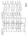
- Fig. 1 is a block diagram of the multiplexed control system 10 particularly suited for a vehicle.
- the system 10 comprises a light source 12, a power source 14, and at least one control panel 16.
- the light source 12 may be of the type described in the aforementioned EP 89 119 402.9.
- the light source 12 is centrally located within the vehicle and of a high brightness level more than sufficient to provide all of the illumination needs of the vehicle.
- the light source 12 generates light energy for a plurality of light busses which are routed within vehicle and provide the light energy for vehicle lighting devices.
- the light source 12 has four (4) separate light busses shown as 12A (light buss A), 12B (light buss B), 12C (light buss C), and 12D (light buss D).
- the light busses 12A, 12B, 12C, and 12D are respectively routed to the at least one control panel 16, and interface devices 24, 26, and 28.
- the control panel 16 is also responsive to operator initiated commands signifying the forthcoming motion of the vehicle such as stop, turn and brake commands typically initiated from or near the steering column of the vehicle.
- the at least one control panel 16 generates a plurality of output signals LIA...MIN each respectively representative of the operator initiated commands.
- Control logic 22 is responsive to the output signals LIA...MIN and generates corresponding control signals onto a control buss 22I, having various embodiments to be described.
- a device 32 is provided for respectively interfacing each of the electrically activated devices and each of the lighting devices with the control buss 22I.
- Each of these control buss interfacing devices 32 responds to the corresponding respective output signal related to the electrically activated devices or the lighting devices, which, in turn, generate output signals in response thereto.
- Devices 24, 26 and 28 respectively interface each of the lighting devices with a related light buss.
- Each of the light buss interfacing device 24, 26 and 28 couples the related lighting device to the related light buss in response to the respective output signal from the corresponding control buss interfacing device.
- the device 30 provides for respectively interfacing each of the electrically activated devices with the power buss 14A.
- Each of these power buss interfacing devices couples its respective electrically activated device to the power buss in response to respective output signals from the corresponding control buss interfacing device.
- the at least one control panel 16 has various embodiments one of which is shown in Fig. 2 and may be conveniently located relative to the operator of the vehicle. Other control panels may be distributed within the vehicle and positioned at the same location of the electrically activated devices or lighting devices; e.g., at the door or doors where the door locks are located.
- the control or the displays of one or more control panels are typically associated with lighting devices, electrically activated devices and sensors and some of which are given in Table 1.
- the activation of the associated equipment given in Table 1 may be accomplished in various manners one of which is that the courtesy and dome lights may be operated electrically and come on when any door of the vehicle is opened.
- the light source 12 coupled to light buss 12A, which is connected to control panel 16, may be activated when the key of the vehicle is placed into the keyhole on the steering column.
- the control panel 16 of Fig. 2 has an input stage 34 supplied, in part, from light buss 12A and which is responsive to the operator initiated commands 18.
- the control panel has an input stage 34 for accepting input commands, a processing stage 36 for determination of and response to the received commands, and an output stage 38 to provide the drive signals to various embodiments of the control logic 22.
- the input stage 34 also interfaces with and is responsive to electrical signals generated by the various switch actions from a plurality of switches typically located near or on a steering column 20.
- the excitation for the plurality of the switches related to the steering column along with the other devices responsive to operator commands 18 may be from the power buss 14A or as will be described hereinafter with regard to Fig. 8 from a light buss such as 12A.
- the input stage 34 generates output signals 34A...34N which correspond to the active or inactive state of the commands receivable at the input stage 34.
- the output signals 34A...34N are routed to a processing stage 36.
- the processing stage 36 in response to input signals 34A...34N generates output signals 36A...36N which are indicative of the commands of the various lighting devices and electrically activated devices whose operating condition is determined by the operator of the vehicle or its occupants.
- the output signals 36A...36N are routed to the output stage 38.
- the output stage 38 generates signals LIA...LIN which determine the active or inactive state of all of the various electrical devices related to the present invention within the automobile. This determination may be first described with reference to Table 2.
- Table 2 illustrates the interrelationship between control signals LIA...MIN of control buss 22I and the active state S2 of vehicle electrical devices comprising lighting device I, lighting device II, lighting device III, and electrically activated device I.
- Each of the vehicle electrical devices along with their related control buss, lighting buss and power buss devices are each composed of a series of similar devices classified as A through N, with N signifying the last number in any arranged series.
- the control signals LIA...LIN, LIIA...LIIN, LIIIA...LIIIN, and MIA...MIN respectively correspond to lighting device IA... lighting device IN, lighting device IIA... lighting device IIN, lighting device IIIA... lighting device IIIN, and electrically activated device IA... electrically activated device IN.
- Each of the vehicle electrical devices have operational states S1 and S2 which are respectively indicative of the inactive (S1) or active state (S2) of each of the related electrical devices and wherein the active states (S2) are only shown in Table 1.
- S1 and S2 are respectively indicative of the inactive (S1) or active state (S2) of each of the related electrical devices and wherein the active states (S2) are only shown in Table 1.
- the interrelationship between the vehicle electrical devices and the control signals LIA...MIN may be further described with reference to Fig. 1.
- the active or inactive state of the vehicle electrical devices of Fig. 1 are determined by their inactive or active status relative to the three (3) different types of busses shown in Fig. 1, which are control buss 22I, light busses comprising 12A, 12B, 12C, and 12D, and the power buss 14A.
- the interrelationship between the vehicle electrical devices and the busses shown on Fig. 1 is given in Table 3.
- the active or inactive state of the electrical devices of Table 3 is determined by the presence or absence of the control signals of control buss 22 shown in Table 2.
- control signal LIA of Table 2 causes the lighting device IA of Table 3 to obtain its active or operational state S2
- control signal MIN of Table 2 causes the electrically activated device IN of Table 3 to obtain its active or operational state S2.
- the absence of control signals LIA and MIN respectively prevents lighting device IA and electrically activated device IN to seek or obtain their active state S1.
- the presence or absence of these control signals LIA...MIN is dependent upon the active or inactive state of the operator initiated commands 18 or the commands initiated from the external panel such as the vehicle steering column 20.
- the present invention contemplates various techniques for generating these control signals some of the embodiments of which are illustrated Figs. 3, 4(a), 4(b), 6, 8(a), 8(b) and 8(c) showing four (4) separate control logic 22 mechanizations.
- Fig. 3 illustrates an arrangement 40, included into and designated as 22 (control logic A), that comprises a plurality of optical fibers 22I(LIA)...22I(MIN) for conducting light which is respectively generated in response to the output signals LIA...MIN of the control panel 16, which, in turn, is respectively responsive to the operator commands 18 and the signals from the steering column 20 shown in Fig. 2.
- the control logic A of Fig. 3 provides an optical control device 42 for each of the control signals LIA...MIN generated by the control panel 16.
- the device 42 may be comprised of optoelectronic circuits that accept an electrical signal, such as LIA, at the input stage and convert such to an optical signal i.e., 22I (LIA).
- Each of the optical devices 42 may have routed to it the light present on light buss 12A.
- Each of the electrical output signals generated by the control panel 16 is received and converted by respectively devices 42 into an optical signals that are respectively routed to separate optical fibers 22I(LIA)...22I(MIN).
- the respective optical fibers may be routed to the control buss devices or directly to the lighting buss devices in a manner as shown in Table 4.
- the optical control provided by the embodiment of Fig. 3 allows for the direct routing of the optical fiber into the lighting buss interface device related to the lighting device to be controlled by the light signal present on the optical fiber, thereby bypassing the need for a separate control element 32 for communicating with buss 22I.
- the embodiment of Fig. 3 eliminates the need for control elements 32, the reduction of the complexity of the wiring device related to the electrical system discussed in the "Background" section of the present invention is not reduced by an amount capable by the practice of the present invention. This limitation is removed by the embodiments shown in Figs. 4(a), 4(b) and 6.
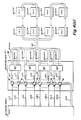
- Fig. 4(a) illustrates an arrangement 44, included into and designated as 22 (control logic B), which has a series of light coding network 46A, 46B, 46C and 46D respectively having as their inputs the signals LIA...LIN, LIIA...LIIN, LIIIA...LIIIN, and MIA...MIN.
- the front end of control logic B is similar to the previously described control logic (22) in that it has a optical device 42 for accepting each of these electrical signals LIA...MIN and converting such electrical signals into optical signals that are routed to respective optical fibers, which, in turn are routed to the four (4) groups of color coding networks 46A, 46B, 46C, and 46D respectively.
- These networks 46A...46D provide light signals serving as the output signals of the control logic B which are applied to the control buss 22I and are comprised of different colors. The different colors each signify a particular control signal for the control buss interface devices 32.
- the control buss 22I comprises a light guide that is routed to in a serial manner (shown in Fig. 4(a)) or in a parallel manner (not shown) to all of the control buss interface devices 32 given in Tables 3 and 4.
- the optical signals that are present on light guide 22I are comprised of different colors so as to serve as different commanded functions.
- the color coding network 42A may provide a blue color in response the presence of each or all of the control signals LIA...LIN so as to respectively command the activation of lighting device IA and/or lighting device IN.
- the light coding network 46B may develop a yellow light in response to the presence of each or all of control signals LIIA...LIIN so as to respectively activate lighting device IIA and/or lighting device IIN.
- the presence of the yellow light on light guide 22I generated by the light coding network 46B will not activate the lighting device IA, and similarly, the presence of the blue light generated by the light coding network 46A will not activate the lighting device IIA.
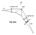
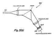
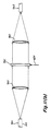
- Fig. 4(b) representative, for example, of the color coding networks 46A, in which refraction or diffraction is used to spread out light according to its color.
- the light rays related to LIA are emitted from an optical fiber and intercepted by a collimating lens, which, in turn, directs the intercepted light rays into a prism.
- the prism spreads or separates the rays according to color and directs such color rays onto a focussing lens, which, in turn, directs the rays onto at least two shutters.
- the shutters in their open condition allow the light rays to pass therethrough to be of selectable colors, e.g. red or blue.
- the light rays pass through the colored shutters and into the buss 22I for transmission to the devices of Tables 3 and 4.
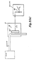
- Fig. 5(a) illustrates a decoding network 46A′ responsive to the different light signal generated by the light coding network 46A of Figs. 4(a) and 4(b).
- the output signal generated by coding network 46A of Fig. 4 is of a particular color that is indicative of the desired activation signal LIA that is used to energize lighting device IA.
- the optical decoding network 46A′ accepts, for example, the blue signal generated by coding network 46 for controlling lighting device IA and responses thereto by providing an electrical signal LIA, which is routed to the lighting buss device 24 (LIA) having at its input stage an arrangement 60 of a light sensitive device and optical transistor device.
- the signal that is developed by device 46A′ may be directly routed to a non-optical transistor device (not shown) of arrangement 60 and thereby eliminate the light sensitive device such as a light emitting diode that is shown for arrangement 60.
- the optical decoding network 46A′ may be of an arrangement shown in Fig. 5(b) which operates in a manner similar to the arrangement of Fig. 4(b) with the difference being related to the detection and response to the light rays emitted by the focussing lens.
- the light rays emitted by the focussing lens first pass through their related colored shutter (red or blue) and appear therefrom as white light and which is then intercepted by an array of respective phototransistor devices that are rendered conductive by the intercepted light so as to generate, for example, the signal LIA shown in Fig. 5(a).
- Control logic C provides light frequency modulated signals as output signals that are applied to the control buss 22I and which are of different light frequencies each indicative of respective control signals LIA...MIN.
- Control logic C is different from control logic B in that it does not have any optical devices at its input stage, but rather directly accepts the electrical output signals generated by the control panel 16 and routes such output signals into the various groups of control signals for the embodiment of Fig. 6.
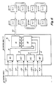
- Fig. 6 For the embodiment shown in Fig.
- control signals LIA...LIN are routed to logic array 62A
- control signals LIIA...LIIN are routed to logic array 62B
- control signals LIIIA...LIIIN are routed to logic array 62C
- control signals MIA...MIN are routed to logic array 62D so that the signals are grouped to four (4) separate functions with each function corresponding to a particular light frequency modulation signals.
- Logic arrays 62A, 62B, 62C, and 62D respectively generate output signals SA, SB, SC and SD which, in turn, are routed to modulation device 64.
- Modulating device 64 serves as a source of modulating signals that are activated or deactivated by the respective presence or absence of signals SA, SB, SC and SD, which, in turn, respectively generate signals MA, MB, MC and MD that are routed to the light frequency transmitter 66.
- the light frequency transmitter 66 generates a frequency modulated light signal responsive to and indicative of one or more of the applied signals MA, MB, MC and MD.
- the different signals indicative of grouping of MA, MB, MC and MD activate or inactivate the electrical devices illustrated in Tables 2, 3 and 4. More particularly, groups MA, MB, MC and MD may be further segmented into MAIA...MAIN, MBIIA...MBIIN, MCIIIA...MCIIIN, and MDIA...MDIN so as to serve as the control signals of Table 2 of LIA...LIN, LIIA...LIIN, LIIIA...LIIIN and MIA and MIN.
- the light frequency modulated signals of transmitter 66 is applied to the control buss 22I which is routed to all of the control buss interface devices of Tables 3 and 4.
- the modulated light present in control buss 22I may be accomplished by acousto-optic, electro-optic, or magneto-optic methods, but it is preferred that such light be in the form of different radio frequency pulses generated by a light emitting diode or laser diode in the output stage of transmitter 66.
- the control buss interface devices related to Fig. 6 have an embodiment illustrated in Fig. 7.
- Fig. 7 illustrates a frequency discriminator 70 responsive to the light frequency modulating signals MAIA generated by the control logic C of Fig. 6.
- the frequency discriminator 70 accepts a control signal MAIA present on control buss 22I, which is indicative of the frequency related to control signal LIA, and in response to that particular frequency, produces an electrical signal that is routed to and controls the device 24 (LIA).
- the frequency discriminator 70 has a tuned amplifier to detect the particular frequency related to the respective device so as to turn-on or render conductive that respective device.
- the detector may be of the optoelectronics art such as being a phototransistor having a related tuned amplifier.
- FIG. 8 shows an optical switch I8I (Fig. 8(a)) which may be used in the optical multiplexed system of the present invention.
- the purpose of the switch 18I is to extract light from the white light within fiber 12A which comes from the light source 12, pass it through a filter (18I A or 18I B of Fig.
- the filter (18I A or 18I B ) passes light of a particular color.
- the electrical device which is to be controlled by the switch has a matching filter 24I B (Fig. 8(c)) corresponding to filter 18I A or 18I B and allows the light acting as, for example, control signal LIA to pass through to the phototransistor 24I A so as to activate the device 24LIA of Fig. 8(c).
- Fig. 8(a) is a top view illustrating an operator control switch 18I which may be mounted on a panel convenient to the operator such as control panel 16.
- the switch 18I comprises the filter member 18I A which may be of a reddish color, the filter member 18I B which may be of a bluish color, and a member 18I C which may be opaque and which separates filters 18I A and 18I B .
- the switch 18I further comprises an arm 18I D which pivots in a manner as shown in phantom in Fig. 8(b).
- the switch 18I is shown in Fig. 8(a) as encompassing at least a portion of an optical fiber serving as the light buss 12A and another optical fiber serving as the control buss 22I.
- fiber 12A is sharply bent as shown in the Fig. 8(a) so that light leaks from fiber 12A at the bend. If the switch 18I is in the position so that the red light is transmitted, that is, the pivot arm is moved clockwise so as to cause the fibers 12A and 22I of Fig. 8(a) to be pressed against filter 18A1, thereby allowing some of the light being transmitted by fiber 12A to enter the second fiber 22I, again at the bend, and which light is transmitted by fiber 22I to the device 24 (LIA) shown in Fig. 8(c).
- the switch 18I is in the position so that the red light is transmitted, that is, the pivot arm is moved clockwise so as to cause the fibers 12A and 22I of Fig. 8(a) to be pressed against filter 18A1, thereby allowing some of the light being transmitted by fiber 12A to enter the second fiber 22I, again at the bend, and which light is transmitted by fiber 22I to the device 24 (LIA) shown in Fig. 8(c).
- a bend in fiber 22I allows some of the transmitted light to escape from the fiber, go through the red filter 24I B to the phototransistor 24I A , and thereby turn-on or activate the 24LIA device.
- a second phototransistor (not shown) with a blue filter is located at the bend of the fiber so as to control the drive of the motor in the opposite direction.
- a single switch can close the window when appropriately pressed so that the red light (18I A ) is transmitted to the second filter 24I B and the window may be opened by moving the switch so that the blue light (18I C ) is transmitted and responded to by an appropriate blue filter and phototransistor located within device 24 (LIA).
- the two sensors may be in a single device with the appropriate filter over each one.
- Figs. 8(a), 8(b) and 8(c) allows for the advantage of only routing four "wires" to any part of the car, for example the door.
- One of these wires may be for the power buss 14A which acts as the hot side of the electrical system
- the second is a light guide from the light source 12 which provides whatever lighting is accomplished from the door, e.g. key hole illumination or courtesy light
- the third is the light guide (fiber) from the control buss 22I (white light) used in the multiplexed control system
- the fourth is the light guide (fiber) coming from the switches 18I carrying the control signals (colored light).
- colored filters may be employed to separate different channels of information.
- the colored filters need to be of a fairly narrow band in operation which is commonly termed "spike filters".
- spike filters To be able to use many channels of information for the embodiments of Figs. 4(a), 4(b), 5(a) and 5(b), it is desirable that the white light be continuous, that is, to cover all of electromagnetic spectrum related to visible light rather than one or more particular color portions of the visible light spectrum.
- a light source is preferred in which the light is produced by an incandescent filament or perhaps by a xenon discharge source rather than a metal halide lamp in which the white light consists of a mixture of many color emission lines.
- filters might be picked to match emission lines so that a mercury or metal halide lamp would be suitable.
- the selection of the type of light source depends on how many channels of information are needed to control all of the vehicle electrical devices shown in Fig. 1.
- the lighting buss interface device 24(LIA) and also the other devices 24LIN, 26LIIA...26LIIN, 28LIIIA...28LIIIN and 30MIA...30MIN all preferably have at their input stage an optical sensitive device each of which are activated by respective control buss interface devices 32.
- These devices 24, 26, 28 and 30 have different embodiments so as to serve the particular needs of their related lighting or electrically activated devices.
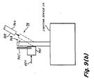
- Devices 24(LIA)...24(LIN) may have an embodiment illustrated in Fig. 9(a).
- the device 24 may comprise an optical switching network 74 shown in Fig. 9(a) as having a first or upper port 74A directly coupled to the light buss 12B and a second or lower port 74B directly coupled to the lighting device IA.
- the optical switching network 74 has means 74C that is responsive to the output signal 62A developed by the optical switch 62 of arrangement 60 of 24I A of Fig. 8 in response to a control signal LIA from the embodiments of Figs. 3, 4(a) and 4(b), 5(a) and 5(b), 6 or 8.
- the optical switching network 74 may be comprised of an arrangement which is schematically illustrated in Fig. 9(b).
- the optical switching network 74 is responsive to the optical switch 62 and comprises a device which moves an optical carrying member in and out of alignment with its respective light buss.
- the means 74C responsive to the signal 62A may comprise a piezoelectric device having an arm 74C′ that is positioned under an optical fiber serving as the output port 74B that is routed to lighting device IA.
- the device 74C upon receiving the signal 62A causes the arm 74C′ to be moved upward and thereby raising fiber 74B up to alignment (shown in phantom) with light buss 12B allowing the light emitted from buss 12B to enter into fiber 74B for conduction to the lighting device IA.
- the removal of signal 62A causes the fiber 74b to return to its at-rest position which does not allow any to the light from light buss 12B to enter into fiber 74B.
- the movement of fiber 74B to and from its at-rest position may be accomplish by electromagnetic, pneumatic bimetal or memory metal devices in lieu of the described piezoelectric means.
- the device 24 is adapted to provide the light excitation for the lighting device IA which may have various forms, such as, a headlight or a fog light.
- the needs of lighting device IA are essentially that of being a device that may either be in its active or inactive state, thereby providing for the automotive needs such as high or low beam illumination.
- the control of the excitation, that is the active or inactive state of the lighting device IA is determined by the presence or absence of control signal LIA. If desired, the lighting device IA may be of a flashing arrangement e.g., turn signal by allowing the periodic occurrence and removal of the control signal LIA from the device 24.
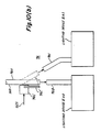
- Devices 26(LIIA)...26(LIIN) may be of an embodiment illustrated in Fig. 10(a).
- Device 26 may comprise an optical interruption network 76 having an input port 76A, two output ports 76B and 76C, and means 74C described with regard to Fig. 9(b).
- the first port 76A is directly coupled to light buss 12D and second port 76B and third port 76C are respectively, directly coupled to the lighting devices IIA1 and IIA2.
- the optical switching network 76 may be comprised of an arrangement which is schematically illustrated in Fig. 10(b).
- the optical switching network 76 is responsive to said optical switch 62 and comprises a device which moves an optical carrying member in and out of alignment with the respective light buss.
- the device 74C upon receiving the signal 62A causes the arm 74C′ to be moved upward and thereby raising fiber 76A up to alignment (shown in phantom) with optical fiber 76C so as to allow the light emitted from buss 12D to enter into fiber 76C for conduction to the light device IIA1.
- the removal of signal 62A causes the fiber 76A to return to its at rest position which allows the light emitted from buss 12D to enter into fiber 76B for conduction to lighting device IIA2.
- the device 26 adapts the lighting devices IIA1 and IIA2 to the needs of the automobile.
- the lighting device IIA1 and IIA2 may provide for the turn signal means of the automobile.
- the turn signal light energy is existing within the lighting buss 12D and the flashing which indicates the turn signals function is accomplished by having the means 74C alternately couple light energy from light buss 12B into the lighting device IIA1 and then into lighting device IIA2.
- the flashing control for the lights in the front and in the rear may be alternately activated.
- Various means can also be used for controlling the stop-turn warning lights, so that the flashing may be done by a simple rotating mirror that alternately directs light from the front of the vehicle to the rear of the vehicle.
- Device 28(LIIIA)...26(LIIIN) may have an embodiment illustrated in Fig. 11(a) and adapts the lighting device III to the needs of the automobile.
- the device 28 provides a light adjustment function that may find usage in the instrumentation panel of a vehicle.
- the device 28 illustrated in Fig. 11(a) comprises a light attenuation network 78 having a first port 78A and a second port 78B with the first port 78A being directly connected to lighting buss 12C, and the second port being directly routed to lighting device IIIA.
- the lighting attenuation network 78 may further has means 78C which is responsive to the signals 62A generated by the optical switch 62 so that the light conducted from the light buss 12C to the lighting device III is reduced in a variable manner from its highest condition to its lowest or a zero condition.
- the highest and lowest values of this light intensity may be used as a means for adjusting the illumination of the instrumentation panel or cluster in accordance to the ambient conditions of the vehicle.
- the light attenuation network 78 may be comprised of an arrangement which is schematically illustrated in Fig. 11(b).
- the light attenuation is primarily accomplished by means 78C that alters its transparency from substantially clear, allowing about 100% of light to pass therethrough, to substantially cloudy, allowing about 5% of light to pass therethrough, in response to the electrical signal 62A.
- the network 78 further comprises a colluminating lens 78D which gathers the light emitted from fiber 78A and passes such light so as to impinge unto means 78C.
- the means 78C performs its attenuation and passes the light unto a focussing lens 78E, which, in turn, directs the light into fiber 78B for transmittal to lighting device IIIA.
- Fig. 12 generally illustrates a movable device 80 which is controlled by a motor device 80A having a gearing arrangement 80B connected to the moveable device 80.
- the motor device 80A is in turn controlled by a motor control 80C, which, in turn, is responsive to the output signal 62A generated by the optical device 62.
- the motor control 80C has one end directly connected to the power buss 14A.
- the motor control 80C in response to the output signal 62A causes the movement of the moveable or maneuverable device which may be a window, seat, trunk lock, door lock or other operator controlled vehicle equipment.
- the motor control 80C in response to a feedback path 80D terminates such movement of device 80.
- the practice of the present invention provides a means for controlling all of the lighting devices and all of the electrically activated devices operable by an occupant of a vehicle.
- the optical energy for all of the lighting devices is developed by the light source 12, and is routed to all of the lighting devices by means of the lighting busses 12A, 12B, 12C and 12D.
- various methods are used such as the use of optical light coding and decoding or light frequency modulation coding and decoding or the separate use of fiber optics for selectable control of individual functions.
- the multiplexed distribution system of the present invention provides various embodiments that all satisfy the needs of a vehicle while at the same time reduces the electrical wiring harnesses complexity of the vehicle.
Abstract
Description
- The present invention relates to an electrical distribution system for a vehicle, and more particularly, to an optical multiplexed distribution system that reduces the complexity of the electrical wiring harness of a vehicle.
- As discussed in U.S. Patent 4,811,172 and assigned to same assignee as a present invention, it is known that fiber optics may be used efficiently to carry the output of a light source to various locations without encountering any substantial transmission losses thereof. The optical fibers in cooperation with a high brightness light source finds various related space restricted applications such as encountered for aerodynamically styled vehicles.
- Similarly, as disclosed in EP 89 119 402.9 a centralized lighting system which is particularly suited for vehicles comprises an integrated high brightness light source which is coupled to optical light guides and serves the lighting needs of the vehicle.
- While the above two (2) disclosures provide light generating and distribution systems for a vehicle, there still remains a need to reduce the complexity of the light generating and distribution system, along with the overall electrical distribution system, in particular, the wiring harness related to the electrical needs of the vehicle. Some of the problems that create the complexity of the electrical distribution system of a vehicle, is that the switches for illuminating or motorizing devices that may be activated by a driver must be located in a convenient location while the function being switched may be physically and visibly quite remote and possibly in a number of locations. For example, the emergency flashes of a vehicle are commonly activated from the steering column, but the related blinker devices activate at least four (4) lamps on and off that are located on the front and rear of the vehicle. The circuit to accomplish this function is further complicated by the fact that the same four (4) lamps are also used to provide turn signals and, in some cases, the related lamps are also used as brake lights. A similar complication exists with regard to the electrically activated devices, such as, door locks being located on individual doors for selectability while the overall control may be on a panel within the direct reach of the driver. As a result of these complexities, the wiring harness for a vehicle is a relatively complex arrangement having the need for simplification.
- Accordingly, it is an object of the present invention to provide a control system that reduces the complexity of the related wiring harness for illuminating and electrically activated devices of a vehicle.
- The present invention is directed to a multiplexed control scheme that reduces the complexity of the electrical distribution system of a vehicle. The control system comprises a light source, a power source, a control buss, light busses and a power buss. The control system further comprises at least one control panel, various control logic, control buss interfacing devices, light buss interfacing devices and power buss interfacing devices.
- The light source generates light energy for a plurality of the light busses which are routed within the vehicle. The power source by means of the power buss is routed to and provides electrical energy to operator controlled electrically activated devices of the vehicle. The at least one control panel is connected to one of the light busses and is responsive to a plurality of operator initiated commands for controlling the electrically activated devices along with lighting devices of a vehicle. The control panel is also responsive to operator initiated commands, such as turn signal devices, signaling the forthcoming motion of the vehicle. The control panel generates a plurality of output signals each respectively representative of the operator initiated commands. The control logic is responsive to the output signals of the control panel and generates corresponding control signals onto a control buss routed throughout the vehicle. The electrically activated devices and the lighting devices are each provided with a device to mate into and communicate with the control buss. Each of the control buss interfacing devices responds to the respective output signals of the control logic related to the electrically activated devices and the lighting devices. A device is provided for respectively interfacing each of the lighting devices with an associated light buss. Each of the lighting buss interface devices couples its respective lighting device to its light buss in response to a corresponding output signal from the respective control buss interfacing device. A device is provided for respectively interfacing each of the electrically activated devices with the power buss. Each of the power buss interfacing devices is coupled to respective electrically activated devices in response to a respective output signal from its respective control buss interfacing device.
-
- Fig. 1 is a block diagram of the multiplexed control system for a vehicle according to the present invention.
- Fig. 2 is a block diagram generally illustrating the interconnections of the external devices under operator control of one embodiment of at least one control panel related to the present invention.
- Fig. 3 is a block diagram of a first embodiment of the control logic employing a plurality of output optical fibers.
- Figs. 4(a) and 4(b) are respectively a block diagram and a schematic arrangement of another embodiment of the control logic employing color coding as a multiplexing scheme for transmission.
- Figs. 5(a) and 5(b) are respectively a schematic block diagram and a schematic arrangement of a control buss interface device related to the control logic of Figs. 4(a) and 4(b).
- Fig. 6 is a block diagram of a further embodiment of the control logic employing light frequency coding as a multiplexing scheme for transmission.
- Fig. 7 is a block diagram of the control buss device related to the control logic embodiment of Fig. 6.
- Figs 8(a) and 8(b) and 8(c) are schematic block diagrams of one embodiment of initiating and color coding a control signal which is applied to the control buss and responded to by a lighting buss interfacing device.
- Figs. 9(a) and 9(b) are respectively a schematic block diagram and a schematic arrangement of a first lighting buss interface device related to the present invention.
- Figs. 10(a) and 10(b) are respectively a block diagram schematic and a schematic arrangement of a second lighting buss interface device related to the present invention.
- Figs. 11(a) and 11(b) are respectively a block diagram schematic and a schematic arrangement of another lighting buss interface device related to the present invention.
- Fig. 12 is a block diagram schematic of a power buss interface device related to the present invention.
- Referring to the drawing, Fig. 1 is a block diagram of the
multiplexed control system 10 particularly suited for a vehicle. Thesystem 10 comprises alight source 12, apower source 14, and at least onecontrol panel 16. - The
light source 12 may be of the type described in the aforementioned EP 89 119 402.9. - The
light source 12 is centrally located within the vehicle and of a high brightness level more than sufficient to provide all of the illumination needs of the vehicle. Thelight source 12 generates light energy for a plurality of light busses which are routed within vehicle and provide the light energy for vehicle lighting devices. For the embodiment shown in Fig. 1, thelight source 12 has four (4) separate light busses shown as 12A (light buss A), 12B (light buss B), 12C (light buss C), and 12D (light buss D). Thelight busses control panel 16, andinterface devices - The
power source 14, illustrated as a typical automotive battery, provides the excitation that is applied to power buss 14A which is routed to and provides electrical energy to electrically activated devices of the vehicle related to the present invention and which are under control of the operator initiated responses selectable from thecontrol panel 16. Thecontrol panel 16 is also responsive to operator initiated commands signifying the forthcoming motion of the vehicle such as stop, turn and brake commands typically initiated from or near the steering column of the vehicle. The at least onecontrol panel 16 generates a plurality of output signals LIA...MIN each respectively representative of the operator initiated commands.Control logic 22 is responsive to the output signals LIA...MIN and generates corresponding control signals onto acontrol buss 22I, having various embodiments to be described. - A
device 32 is provided for respectively interfacing each of the electrically activated devices and each of the lighting devices with thecontrol buss 22I. Each of these controlbuss interfacing devices 32 responds to the corresponding respective output signal related to the electrically activated devices or the lighting devices, which, in turn, generate output signals in response thereto. -
Devices buss interfacing device device 30 provides for respectively interfacing each of the electrically activated devices with the power buss 14A. Each of these power buss interfacing devices couples its respective electrically activated device to the power buss in response to respective output signals from the corresponding control buss interfacing device. - The at least one
control panel 16 has various embodiments one of which is shown in Fig. 2 and may be conveniently located relative to the operator of the vehicle. Other control panels may be distributed within the vehicle and positioned at the same location of the electrically activated devices or lighting devices; e.g., at the door or doors where the door locks are located. The control or the displays of one or more control panels are typically associated with lighting devices, electrically activated devices and sensors and some of which are given in Table 1. - HEADLAMPS ON-OFF
HEADLAMPS HIGH-LOW
PARKING
TURN SIGNAL
CORNERING
FLASHERS
STOP
BACKING
DOME
GLOVE
COURTESY - WIPERS MIST, LOW, HIGH
WASHERS
MIRRORS
LOCKS - DRIVERS DOOR AND EACH DOOR
COMBINATION LOCK - DRIVERS DOOR AND EACH DOOR
WINDOWS - DRIVERS DOOR AND EACH DOOR
TRUNK LATCH
HEATER FAN
CRUISE CONTROL
AIR CONDITIONING
RADIO - GAS
OIL PRESSURE
OIL LEVEL
SPEED
RPM
WATER TEMP
WATER LEVEL
WASHER FLUID
BATTERY ACID
DOOR OPEN-DOME LIGHT-COURTESY LIGHT-WARNING CHIME
KEY LEFT WARNING-WARNING CHIME
HEADLIGHT ON WARNING-WARNING CHIME - The activation of the associated equipment given in Table 1 may be accomplished in various manners one of which is that the courtesy and dome lights may be operated electrically and come on when any door of the vehicle is opened. The
light source 12 coupled tolight buss 12A, which is connected to controlpanel 16, may be activated when the key of the vehicle is placed into the keyhole on the steering column. - The
control panel 16 of Fig. 2 has aninput stage 34 supplied, in part, fromlight buss 12A and which is responsive to the operator initiated commands 18. For the embodiment shown in Fig. 2, the control panel has aninput stage 34 for accepting input commands, aprocessing stage 36 for determination of and response to the received commands, and anoutput stage 38 to provide the drive signals to various embodiments of thecontrol logic 22. Theinput stage 34 also interfaces with and is responsive to electrical signals generated by the various switch actions from a plurality of switches typically located near or on asteering column 20. The excitation for the plurality of the switches related to the steering column along with the other devices responsive to operator commands 18 may be from the power buss 14A or as will be described hereinafter with regard to Fig. 8 from a light buss such as 12A. Theinput stage 34 generatesoutput signals 34A...34N which correspond to the active or inactive state of the commands receivable at theinput stage 34. The output signals 34A...34N are routed to aprocessing stage 36. - The
processing stage 36 in response toinput signals 34A...34N generatesoutput signals 36A...36N which are indicative of the commands of the various lighting devices and electrically activated devices whose operating condition is determined by the operator of the vehicle or its occupants. The output signals 36A...36N are routed to theoutput stage 38. Theoutput stage 38 generates signals LIA...LIN which determine the active or inactive state of all of the various electrical devices related to the present invention within the automobile. This determination may be first described with reference to Table 2.TABLE 2 VEHICLE ELECTRICAL DEVICES ACTIVE STATE CONTROL BUSS 22I LIGHTING DEVICE I LIGHTING DEVICE II LIGHTING DEVICE III ELECTRICALLY ACTIVATED DEVICE A ● ● N A ● ● N A ● ● N A ● ● N CONTROL SIGNALS S2 S2 S2 S2 S2 S2 S2 S2 S2 S2 S2 S2 S2 S2 S2 S2 (LIA) X ● X ● X (LIN) X (LIIA) X ● X ● X (LIIN) X (LIIIA) X ● X ● X (LIIIN) X (MIA) X ● X ● X (MIN) X - Table 2 illustrates the interrelationship between control signals LIA...MIN of
control buss 22I and the active state S2 of vehicle electrical devices comprising lighting device I, lighting device II, lighting device III, and electrically activated device I. Each of the vehicle electrical devices along with their related control buss, lighting buss and power buss devices are each composed of a series of similar devices classified as A through N, with N signifying the last number in any arranged series. The control signals LIA...LIN, LIIA...LIIN, LIIIA...LIIIN, and MIA...MIN respectively correspond to lighting device IA... lighting device IN, lighting device IIA... lighting device IIN, lighting device IIIA... lighting device IIIN, and electrically activated device IA... electrically activated device IN. Each of the vehicle electrical devices have operational states S1 and S2 which are respectively indicative of the inactive (S1) or active state (S2) of each of the related electrical devices and wherein the active states (S2) are only shown in Table 1. The interrelationship between the vehicle electrical devices and the control signals LIA...MIN may be further described with reference to Fig. 1. - The active or inactive state of the vehicle electrical devices of Fig. 1 are determined by their inactive or active status relative to the three (3) different types of busses shown in Fig. 1, which are
control buss 22I, light busses comprising 12A, 12B, 12C, and 12D, and the power buss 14A. The interrelationship between the vehicle electrical devices and the busses shown on Fig. 1 is given in Table 3.TABLE 3 Vehicle Electrical Device Control Buss Device Lighting Buss Device Power Buss Device Lighting Device LIA 32 24 (LIA) Lighting Device LIN 32 24 (LIN) Lighting Device IIA1, IIA2 32 26 (LIIA) Lighting Device IIN1, IIN2 32 26 (LIIN) Lighting Device IIIA 32 26 (LIIIA) Lighting Device IIIN 32 26 (LIIIN) Electrically Activated Device IA 32 30 (MIA) Electrically Activated Device IN 32 30 (MIN) - The active or inactive state of the electrical devices of Table 3 is determined by the presence or absence of the control signals of
control buss 22 shown in Table 2. For example, the presence of control signal LIA of Table 2 causes the lighting device IA of Table 3 to obtain its active or operational state S2, whereas, the presence of control signal MIN of Table 2 causes the electrically activated device IN of Table 3 to obtain its active or operational state S2. Conversely, the absence of control signals LIA and MIN respectively prevents lighting device IA and electrically activated device IN to seek or obtain their active state S1. The presence or absence of these control signals LIA...MIN is dependent upon the active or inactive state of the operator initiatedcommands 18 or the commands initiated from the external panel such as thevehicle steering column 20. The present invention contemplates various techniques for generating these control signals some of the embodiments of which are illustrated Figs. 3, 4(a), 4(b), 6, 8(a), 8(b) and 8(c) showing four (4)separate control logic 22 mechanizations. - Fig. 3 illustrates an
arrangement 40, included into and designated as 22 (control logic A), that comprises a plurality ofoptical fibers 22I(LIA)...22I(MIN) for conducting light which is respectively generated in response to the output signals LIA...MIN of thecontrol panel 16, which, in turn, is respectively responsive to the operator commands 18 and the signals from thesteering column 20 shown in Fig. 2. The control logic A of Fig. 3 provides anoptical control device 42 for each of the control signals LIA...MIN generated by the control panel 16.Thedevice 42 may be comprised of optoelectronic circuits that accept an electrical signal, such as LIA, at the input stage and convert such to an optical signal i.e., 22I (LIA). - Each of the
optical devices 42 may have routed to it the light present onlight buss 12A. Each of the electrical output signals generated by thecontrol panel 16 is received and converted by respectivelydevices 42 into an optical signals that are respectively routed to separateoptical fibers 22I(LIA)...22I(MIN). The respective optical fibers may be routed to the control buss devices or directly to the lighting buss devices in a manner as shown in Table 4.TABLE 4 Optical Fiber Control Buss Device Light Buss Device Power Buss Device 22I (LIA) 32 (LIA) 24 (LIA) 22I (LIN) 32 (LIN) 24 (LIN) 22I (LIIA) 32 (LIIA) 26 (LIIA) 22I (LIIN) 32 (LIIN) 26 (LIIN) 22I (LIIIN) 32 (LIIIA) 28 (LIIIA) 22I (LIIIA) 32 (LIIIN) 28 (LIIIN) 22I (MIA) 32 (MIA) 30 (MIA) 22I (MIN) 32 (MIN) 30 (MIN) - The optical control provided by the embodiment of Fig. 3 allows for the direct routing of the optical fiber into the lighting buss interface device related to the lighting device to be controlled by the light signal present on the optical fiber, thereby bypassing the need for a
separate control element 32 for communicating withbuss 22I. Although the embodiment of Fig. 3 eliminates the need forcontrol elements 32, the reduction of the complexity of the wiring device related to the electrical system discussed in the "Background" section of the present invention is not reduced by an amount capable by the practice of the present invention. This limitation is removed by the embodiments shown in Figs. 4(a), 4(b) and 6. - Fig. 4(a) illustrates an
arrangement 44, included into and designated as 22 (control logic B), which has a series oflight coding network 46A, 46B, 46C and 46D respectively having as their inputs the signals LIA...LIN, LIIA...LIIN, LIIIA...LIIIN, and MIA...MIN. The front end of control logic B is similar to the previously described control logic (22) in that it has aoptical device 42 for accepting each of these electrical signals LIA...MIN and converting such electrical signals into optical signals that are routed to respective optical fibers, which, in turn are routed to the four (4) groups ofcolor coding networks 46A, 46B, 46C, and 46D respectively. Thesenetworks 46A...46D provide light signals serving as the output signals of the control logic B which are applied to thecontrol buss 22I and are comprised of different colors. The different colors each signify a particular control signal for the controlbuss interface devices 32. For the embodiment shown in Fig. 4, thecontrol buss 22I comprises a light guide that is routed to in a serial manner (shown in Fig. 4(a)) or in a parallel manner (not shown) to all of the controlbuss interface devices 32 given in Tables 3 and 4. - The optical signals that are present on
light guide 22I are comprised of different colors so as to serve as different commanded functions. For example, the color coding network 42A may provide a blue color in response the presence of each or all of the control signals LIA...LIN so as to respectively command the activation of lighting device IA and/or lighting device IN. Similarly, the light coding network 46B may develop a yellow light in response to the presence of each or all of control signals LIIA...LIIN so as to respectively activate lighting device IIA and/or lighting device IIN. Conversely, the presence of the yellow light onlight guide 22I generated by the light coding network 46B will not activate the lighting device IA, and similarly, the presence of the blue light generated by thelight coding network 46A will not activate the lighting device IIA. - One of the ways to obtain the different colors is to use various filters that are to be discussed with regard to Fig. 8. Another way is shown schematically in Fig. 4(b) representative, for example, of the
color coding networks 46A, in which refraction or diffraction is used to spread out light according to its color. - As seen in Fig. 4(b), the light rays related to LIA are emitted from an optical fiber and intercepted by a collimating lens, which, in turn, directs the intercepted light rays into a prism. The prism spreads or separates the rays according to color and directs such color rays onto a focussing lens, which, in turn, directs the rays onto at least two shutters. The shutters in their open condition allow the light rays to pass therethrough to be of selectable colors, e.g. red or blue. The light rays pass through the colored shutters and into the
buss 22I for transmission to the devices of Tables 3 and 4. The arrangements of Fig. 4(a) and 4(b) allow for one common buss 22A to serve all of the needs of the electrical devices illustrated in Tables 3 and 4 and Fig. 1, and thereby reduces the complexity of the electrical wiring harness related to the vehicle in which the present invention finds application. The light generated by the variouslight coding networks 46A...46D is decoded by thearrangements 50 shown in Figs. 5(a) and 5(b). - Fig. 5(a) illustrates a
decoding network 46A′ responsive to the different light signal generated by thelight coding network 46A of Figs. 4(a) and 4(b). For the embodiment shown in Fig. 5(a), the output signal generated bycoding network 46A of Fig. 4 is of a particular color that is indicative of the desired activation signal LIA that is used to energize lighting device IA. Theoptical decoding network 46A′ accepts, for example, the blue signal generated by coding network 46 for controlling lighting device IA and responses thereto by providing an electrical signal LIA, which is routed to the lighting buss device 24 (LIA) having at its input stage anarrangement 60 of a light sensitive device and optical transistor device. For the embodiment shown in Fig. 5(a), the signal that is developed bydevice 46A′ may be directly routed to a non-optical transistor device (not shown) ofarrangement 60 and thereby eliminate the light sensitive device such as a light emitting diode that is shown forarrangement 60. - The
optical decoding network 46A′ may be of an arrangement shown in Fig. 5(b) which operates in a manner similar to the arrangement of Fig. 4(b) with the difference being related to the detection and response to the light rays emitted by the focussing lens. The light rays emitted by the focussing lens first pass through their related colored shutter (red or blue) and appear therefrom as white light and which is then intercepted by an array of respective phototransistor devices that are rendered conductive by the intercepted light so as to generate, for example, the signal LIA shown in Fig. 5(a). - A further embodiment for developing the control signals for activating the electrical devices of Tables 3 and 4 is shown in Fig. 6 for an
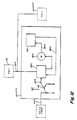
arrangement 60 included in and designated as 22 (control logic C). Control logic C provides light frequency modulated signals as output signals that are applied to thecontrol buss 22I and which are of different light frequencies each indicative of respective control signals LIA...MIN. Control logic C is different from control logic B in that it does not have any optical devices at its input stage, but rather directly accepts the electrical output signals generated by thecontrol panel 16 and routes such output signals into the various groups of control signals for the embodiment of Fig. 6. For the embodiment shown in Fig. 6, the control signals LIA...LIN are routed tologic array 62A, control signals LIIA...LIIN are routed to logic array 62B, control signals LIIIA...LIIIN are routed to logic array 62C and control signals MIA...MIN are routed tologic array 62D so that the signals are grouped to four (4) separate functions with each function corresponding to a particular light frequency modulation signals.Logic arrays modulation device 64. - Modulating
device 64 serves as a source of modulating signals that are activated or deactivated by the respective presence or absence of signals SA, SB, SC and SD, which, in turn, respectively generate signals MA, MB, MC and MD that are routed to thelight frequency transmitter 66. - The
light frequency transmitter 66 generates a frequency modulated light signal responsive to and indicative of one or more of the applied signals MA, MB, MC and MD. In a manner as discussed with regard to the output of control logic B, the different signals indicative of grouping of MA, MB, MC and MD activate or inactivate the electrical devices illustrated in Tables 2, 3 and 4. More particularly, groups MA, MB, MC and MD may be further segmented into MAIA...MAIN, MBIIA...MBIIN, MCIIIA...MCIIIN, and MDIA...MDIN so as to serve as the control signals of Table 2 of LIA...LIN, LIIA...LIIN, LIIIA...LIIIN and MIA and MIN. The light frequency modulated signals oftransmitter 66 is applied to thecontrol buss 22I which is routed to all of the control buss interface devices of Tables 3 and 4. The modulated light present incontrol buss 22I may be accomplished by acousto-optic, electro-optic, or magneto-optic methods, but it is preferred that such light be in the form of different radio frequency pulses generated by a light emitting diode or laser diode in the output stage oftransmitter 66. The control buss interface devices related to Fig. 6 have an embodiment illustrated in Fig. 7. - In a manner similar to that described with regard to Figs. 5(a) and 5(b) relative to the control signal LIA related to lighting buss device 24LIA, Fig. 7 illustrates a frequency discriminator 70 responsive to the light frequency modulating signals MAIA generated by the control logic C of Fig. 6. For the embodiment shown in Fig. 7, the frequency discriminator 70 accepts a control signal MAIA present on
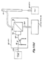
control buss 22I, which is indicative of the frequency related to control signal LIA, and in response to that particular frequency, produces an electrical signal that is routed to and controls the device 24 (LIA). The frequency discriminator 70 has a tuned amplifier to detect the particular frequency related to the respective device so as to turn-on or render conductive that respective device. The detector may be of the optoelectronics art such as being a phototransistor having a related tuned amplifier. - A further embodiment of the present invention that has features similar to the light coding and decoding networks of Figs. 4(a), 4(b), 5(a) and 5(b) is illustrated in Fig. 8 which consists of Figs. 8(a), 8(b) and 8(c). In general, Fig. 8 shows an optical switch I8I (Fig. 8(a)) which may be used in the optical multiplexed system of the present invention. The purpose of the switch 18I is to extract light from the white light within
fiber 12A which comes from thelight source 12, pass it through a filter (18IA or 18IB of Fig. 8(a)), and then introduce it into the other fiber which is routed to all of the lighting and electrically activated devices or other electrical devices which are to be controlled by the practice of the present invention. The filter (18IA or 18IB) passes light of a particular color. The electrical device which is to be controlled by the switch has a matching filter 24IB (Fig. 8(c)) corresponding to filter 18IA or 18IB and allows the light acting as, for example, control signal LIA to pass through to the phototransistor 24IA so as to activate the device 24LIA of Fig. 8(c). - Fig. 8(a) is a top view illustrating an operator control switch 18I which may be mounted on a panel convenient to the operator such as
control panel 16. The switch 18I comprises the filter member 18IA which may be of a reddish color, the filter member 18IB which may be of a bluish color, and a member 18IC which may be opaque and which separates filters 18IA and 18IB. The switch 18I further comprises an arm 18ID which pivots in a manner as shown in phantom in Fig. 8(b). The switch 18I is shown in Fig. 8(a) as encompassing at least a portion of an optical fiber serving as thelight buss 12A and another optical fiber serving as thecontrol buss 22I. - In operation, to extract light from the
first fiber 12A,fiber 12A is sharply bent as shown in the Fig. 8(a) so that light leaks fromfiber 12A at the bend. If the switch 18I is in the position so that the red light is transmitted, that is, the pivot arm is moved clockwise so as to cause thefibers fiber 12A to enter thesecond fiber 22I, again at the bend, and which light is transmitted byfiber 22I to the device 24 (LIA) shown in Fig. 8(c). At the device 24LIA, a bend infiber 22I allows some of the transmitted light to escape from the fiber, go through the red filter 24IB to the phototransistor 24IA, and thereby turn-on or activate the 24LIA device. If double activation is desired, for example, the motor which drives the window up in one case and down in the other, a second phototransistor (not shown) with a blue filter is located at the bend of the fiber so as to control the drive of the motor in the opposite direction. In this way a single switch can close the window when appropriately pressed so that the red light (18IA) is transmitted to the second filter 24IB and the window may be opened by moving the switch so that the blue light (18IC) is transmitted and responded to by an appropriate blue filter and phototransistor located within device 24 (LIA). The two sensors may be in a single device with the appropriate filter over each one. - The embodiment of Figs. 8(a), 8(b) and 8(c) allows for the advantage of only routing four "wires" to any part of the car, for example the door. One of these wires may be for the power buss 14A which acts as the hot side of the electrical system, the second is a light guide from the
light source 12 which provides whatever lighting is accomplished from the door, e.g. key hole illumination or courtesy light, the third is the light guide (fiber) from thecontrol buss 22I (white light) used in the multiplexed control system, and the fourth is the light guide (fiber) coming from the switches 18I carrying the control signals (colored light). - For the embodiments of Figs. 4(a), 4(b), 5(a) and 5(b) employing a light coding multiplexing system, colored filters may be employed to separate different channels of information. The colored filters need to be of a fairly narrow band in operation which is commonly termed "spike filters". To be able to use many channels of information for the embodiments of Figs. 4(a), 4(b), 5(a) and 5(b), it is desirable that the white light be continuous, that is, to cover all of electromagnetic spectrum related to visible light rather than one or more particular color portions of the visible light spectrum. To accomplish such, a light source is preferred in which the light is produced by an incandescent filament or perhaps by a xenon discharge source rather than a metal halide lamp in which the white light consists of a mixture of many color emission lines. Alternatively, filters might be picked to match emission lines so that a mercury or metal halide lamp would be suitable. The selection of the type of light source depends on how many channels of information are needed to control all of the vehicle electrical devices shown in Fig. 1.
- As shown in Fig. 8(c) with reference to device 24IA and as also shown in Figs. 5(a), 5(b) and 7 with reference to
circuit arrangement 60, the lighting buss interface device 24(LIA) and also the other devices 24LIN, 26LIIA...26LIIN, 28LIIIA...28LIIIN and 30MIA...30MIN all preferably have at their input stage an optical sensitive device each of which are activated by respective controlbuss interface devices 32. Thesedevices - Devices 24(LIA)...24(LIN) may have an embodiment illustrated in Fig. 9(a). The
device 24 may comprise an optical switching network 74 shown in Fig. 9(a) as having a first orupper port 74A directly coupled to the light buss 12B and a second or lower port 74B directly coupled to the lighting device IA. The optical switching network 74 hasmeans 74C that is responsive to theoutput signal 62A developed by theoptical switch 62 ofarrangement 60 of 24IA of Fig. 8 in response to a control signal LIA from the embodiments of Figs. 3, 4(a) and 4(b), 5(a) and 5(b), 6 or 8. - The optical switching network 74 may be comprised of an arrangement which is schematically illustrated in Fig. 9(b). The optical switching network 74 is responsive to the
optical switch 62 and comprises a device which moves an optical carrying member in and out of alignment with its respective light buss.The means 74C responsive to thesignal 62A may comprise a piezoelectric device having anarm 74C′ that is positioned under an optical fiber serving as the output port 74B that is routed to lighting device IA. Thedevice 74C upon receiving thesignal 62A causes thearm 74C′ to be moved upward and thereby raising fiber 74B up to alignment (shown in phantom) with light buss 12B allowing the light emitted from buss 12B to enter into fiber 74B for conduction to the lighting device IA. The removal ofsignal 62A causes the fiber 74b to return to its at-rest position which does not allow any to the light from light buss 12B to enter into fiber 74B. The movement of fiber 74B to and from its at-rest position may be accomplish by electromagnetic, pneumatic bimetal or memory metal devices in lieu of the described piezoelectric means. - The
device 24 is adapted to provide the light excitation for the lighting device IA which may have various forms, such as, a headlight or a fog light. The needs of lighting device IA are essentially that of being a device that may either be in its active or inactive state, thereby providing for the automotive needs such as high or low beam illumination.The control of the excitation, that is the active or inactive state of the lighting device IA, is determined by the presence or absence of control signal LIA. If desired, the lighting device IA may be of a flashing arrangement e.g., turn signal by allowing the periodic occurrence and removal of the control signal LIA from thedevice 24. - Devices 26(LIIA)...26(LIIN) may be of an embodiment illustrated in Fig. 10(a).
Device 26 may comprise anoptical interruption network 76 having an input port 76A, twooutput ports 76B and 76C, and means 74C described with regard to Fig. 9(b). The first port 76A is directly coupled tolight buss 12D and second port 76B andthird port 76C are respectively, directly coupled to the lighting devices IIA1 and IIA2. - The
optical switching network 76 may be comprised of an arrangement which is schematically illustrated in Fig. 10(b). Theoptical switching network 76 is responsive to saidoptical switch 62 and comprises a device which moves an optical carrying member in and out of alignment with the respective light buss. Thedevice 74C upon receiving thesignal 62A causes thearm 74C′ to be moved upward and thereby raising fiber 76A up to alignment (shown in phantom) withoptical fiber 76C so as to allow the light emitted frombuss 12D to enter intofiber 76C for conduction to the light device IIA1. The removal ofsignal 62A causes the fiber 76A to return to its at rest position which allows the light emitted frombuss 12D to enter into fiber 76B for conduction to lighting device IIA2. - The
device 26 adapts the lighting devices IIA1 and IIA2 to the needs of the automobile. For example, the lighting device IIA1 and IIA2 may provide for the turn signal means of the automobile. The turn signal light energy is existing within thelighting buss 12D and the flashing which indicates the turn signals function is accomplished by having themeans 74C alternately couple light energy from light buss 12B into the lighting device IIA1 and then into lighting device IIA2. For this type of function, the flashing control for the lights in the front and in the rear may be alternately activated. Various means can also be used for controlling the stop-turn warning lights, so that the flashing may be done by a simple rotating mirror that alternately directs light from the front of the vehicle to the rear of the vehicle. - Device 28(LIIIA)...26(LIIIN) may have an embodiment illustrated in Fig. 11(a) and adapts the lighting device III to the needs of the automobile. The
device 28 provides a light adjustment function that may find usage in the instrumentation panel of a vehicle. Thedevice 28 illustrated in Fig. 11(a) comprises a light attenuation network 78 having afirst port 78A and a second port 78B with thefirst port 78A being directly connected to lightingbuss 12C, and the second port being directly routed to lighting device IIIA. The lighting attenuation network 78 may further hasmeans 78C which is responsive to thesignals 62A generated by theoptical switch 62 so that the light conducted from thelight buss 12C to the lighting device III is reduced in a variable manner from its highest condition to its lowest or a zero condition. The highest and lowest values of this light intensity may be used as a means for adjusting the illumination of the instrumentation panel or cluster in accordance to the ambient conditions of the vehicle. - The light attenuation network 78 may be comprised of an arrangement which is schematically illustrated in Fig. 11(b). The light attenuation is primarily accomplished by
means 78C that alters its transparency from substantially clear, allowing about 100% of light to pass therethrough, to substantially cloudy, allowing about 5% of light to pass therethrough, in response to theelectrical signal 62A. The network 78 further comprises a colluminating lens 78D which gathers the light emitted fromfiber 78A and passes such light so as to impinge unto means 78C. The means 78C performs its attenuation and passes the light unto a focussing lens 78E, which, in turn, directs the light into fiber 78B for transmittal to lighting device IIIA. -
Device 30 adapts the needs of a vehicle motorized device to the control of an operator and may have an embodiment illustrated in Fig. 12. Fig. 12 generally illustrates amovable device 80 which is controlled by a motor device 80A having a gearing arrangement 80B connected to themoveable device 80. The motor device 80A is in turn controlled by a motor control 80C, which, in turn, is responsive to theoutput signal 62A generated by theoptical device 62. The motor control 80C has one end directly connected to the power buss 14A. The motor control 80C in response to theoutput signal 62A causes the movement of the moveable or maneuverable device which may be a window, seat, trunk lock, door lock or other operator controlled vehicle equipment. The motor control 80C in response to a feedback path 80D terminates such movement ofdevice 80. - It should now be appreciated that the practice of the present invention provides a means for controlling all of the lighting devices and all of the electrically activated devices operable by an occupant of a vehicle. With regard to the lighting devices, the optical energy for all of the lighting devices is developed by the
light source 12, and is routed to all of the lighting devices by means of the lighting busses 12A, 12B, 12C and 12D. To selectively activate any of these devices, various methods are used such as the use of optical light coding and decoding or light frequency modulation coding and decoding or the separate use of fiber optics for selectable control of individual functions. The multiplexed distribution system of the present invention provides various embodiments that all satisfy the needs of a vehicle while at the same time reduces the electrical wiring harnesses complexity of the vehicle.
Claims (27)
a gas discharge high intensity light source having a spherical shape and a plurality of light guides merged into its outer surface, said plurality of light guides having respectively connected thereto a plurality of optical light carrying devices serving as said light busses.
an incandescent light source having a plurality of light guides merged into its outer surface, said plurality of light guides having respectively connected thereto a plurality of optical light carrying devices serving as said light busses.
a decoding network responsive to said light signals of said coding network and decoding said different colors to correspond to and provide an electrical signal to selectively activate respective said light buss interfacing devices and said power buss interfacing devices.
a frequency discriminator responsive to said light frequency modulated signals of said coding network and decoding said light frequency modulated signals to correspond to and provide an electrical signal to selectively active respective said light buss interfacing devices and said power buss interfacing devices.
Applications Claiming Priority (2)
| Application Number | Priority Date | Filing Date | Title |
|---|---|---|---|
| US290005 | 1988-12-27 | ||
| US07/290,005 US4930049A (en) | 1988-12-27 | 1988-12-27 | Optical multiplexed electrical distribution system particularly suited for vehicles |
Publications (3)
| Publication Number | Publication Date |
|---|---|
| EP0376056A2 true EP0376056A2 (en) | 1990-07-04 |
| EP0376056A3 EP0376056A3 (en) | 1992-11-19 |
| EP0376056B1 EP0376056B1 (en) | 1995-04-05 |
Family
ID=23114122
Family Applications (1)
| Application Number | Title | Priority Date | Filing Date |
|---|---|---|---|
| EP89122994A Expired - Lifetime EP0376056B1 (en) | 1988-12-27 | 1989-12-13 | Optical multiplexed electrical distribution system particularly suited for vehicles |
Country Status (4)
| Country | Link |
|---|---|
| US (1) | US4930049A (en) |
| EP (1) | EP0376056B1 (en) |
| JP (1) | JPH074030B2 (en) |
| DE (1) | DE68922081T2 (en) |
Cited By (3)
| Publication number | Priority date | Publication date | Assignee | Title |
|---|---|---|---|---|
| EP0591701A2 (en) * | 1992-10-08 | 1994-04-13 | Robert Bosch Gmbh | Control device for electrical users, like signal lights, head lights, windscreen wipers, or the like, in a vehicle |
| EP0655367A1 (en) * | 1993-11-30 | 1995-05-31 | Manuel Martins | New multiplex communication system and vehicle protection system so obtained |
| EP0713807A1 (en) * | 1994-11-22 | 1996-05-29 | FIAT AUTO S.p.A. | A system for distributing electrical energy in motor vehicles, particularly motor cars |
Families Citing this family (30)
| Publication number | Priority date | Publication date | Assignee | Title |
|---|---|---|---|---|
| US5097395A (en) * | 1989-02-24 | 1992-03-17 | Minnesota Mining And Manufacturing Company | Multiple cavity light fixture |
| US5040168A (en) * | 1989-06-30 | 1991-08-13 | United Technologies Automotive, Inc. | Single wire, infrared, randomly reflected, vehicular multiplexing system |
| DE4038433A1 (en) * | 1990-12-01 | 1992-06-04 | Bosch Gmbh Robert | LIGHTING DEVICE FOR VEHICLES |
| DE4040020C2 (en) * | 1990-12-14 | 1999-07-15 | Bosch Gmbh Robert | Lighting device for vehicles |
| DE69230098T2 (en) * | 1992-06-02 | 2000-05-25 | Procter & Gamble | Bleaching composition for laundry |
| US5436805A (en) * | 1992-10-29 | 1995-07-25 | Hughes Aircraft Company | Thermally insulated distributed light network from a central light source |
| US5311410A (en) * | 1992-10-29 | 1994-05-10 | Hughes Aircraft Company | Distributed lighting system with fiber optic controls |
| US5390265A (en) * | 1993-12-17 | 1995-02-14 | General Motors Corporation | Fiber optic light coupler |
| US5713654A (en) * | 1994-09-28 | 1998-02-03 | Sdl, Inc. | Addressable laser vehicle lights |
| US6152588A (en) | 1994-09-28 | 2000-11-28 | Sdl, Inc. | Addressable vehicular lighting system |
| EP0807032B1 (en) * | 1995-02-02 | 2000-09-13 | Federal Signal Corporation | System and method for broadcasting colored light for emergency signalling |
| US5764010A (en) * | 1995-04-28 | 1998-06-09 | United Technologies Automotive, Inc. | Control system for an automotive vehicle multi-functional apparatus |
| US5691696A (en) * | 1995-09-08 | 1997-11-25 | Federal Signal Corporation | System and method for broadcasting colored light for emergency signals |
| DE19610138C2 (en) * | 1996-03-15 | 2000-07-13 | Daimler Chrysler Aerospace | Reading lamp system for a passenger plane |
| EP0889803A1 (en) * | 1996-03-28 | 1999-01-13 | Weldon Technologies, Inc. | Dual lamp fixture with integral control |
| US6095673A (en) * | 1998-01-20 | 2000-08-01 | The Whitaker Corporation | Co-extruded light pipe |
| DE19931838C1 (en) * | 1999-07-09 | 2001-10-31 | Daimler Chrysler Ag | Method for checking a ring-shaped optical network line for data transmission between several network participants in a motor vehicle |
| DE19944967C2 (en) * | 1999-09-14 | 2002-01-24 | Brose Fahrzeugteile | Transmission system for data and control signals in a motor vehicle |
| DE10105858A1 (en) * | 2001-02-08 | 2002-08-14 | Deere & Co | Communication system of a vehicle |
| US20060285350A1 (en) * | 2005-06-17 | 2006-12-21 | Bwt Property, Inc. | A Lighting System for Navigational Aids |
| US7362936B2 (en) * | 2006-03-01 | 2008-04-22 | Defense Photonics Group, Inc. | Optical harness assembly and method |
| US9190809B2 (en) | 2012-12-29 | 2015-11-17 | Zephyr Photonics Inc. | Method and apparatus for active voltage regulation in optical modules |
| US9468085B2 (en) | 2012-12-29 | 2016-10-11 | Zephyr Photonics Inc. | Method and apparatus for implementing optical modules in high temperatures |
| US9728936B2 (en) | 2012-12-29 | 2017-08-08 | Zephyr Photonics Inc. | Method, system and apparatus for hybrid optical and electrical pumping of semiconductor lasers and LEDs for improved reliability at high temperatures |
| US10958348B2 (en) | 2012-12-29 | 2021-03-23 | Zephyr Photonics Inc. | Method for manufacturing modular multi-function active optical cables |
| US9160452B2 (en) | 2012-12-29 | 2015-10-13 | Zephyr Photonics Inc. | Apparatus for modular implementation of multi-function active optical cables |
| US9172462B2 (en) | 2012-12-31 | 2015-10-27 | Zephyr Photonics Inc. | Optical bench apparatus having integrated monitor photodetectors and method for monitoring optical power using same |
| CN103112390A (en) * | 2013-01-19 | 2013-05-22 | 高东杰 | Novel automobile light control method |
| JP7053028B2 (en) * | 2018-08-09 | 2022-04-12 | 国立研究開発法人情報通信研究機構 | In-vehicle optical network |
| US11951905B1 (en) * | 2023-07-24 | 2024-04-09 | GM Global Technology Operations LLC | Fiber-optic with piezoelectric actuated projection display |
Citations (2)
| Publication number | Priority date | Publication date | Assignee | Title |
|---|---|---|---|---|
| DE3434536A1 (en) * | 1983-05-21 | 1986-03-20 | Joachim Dipl.-Phys. 5020 Frechen Schick | Optical waveguide system for example for the rear light groups of motor vehicles |
| US4851969A (en) * | 1988-12-27 | 1989-07-25 | General Electric Company | Optical control system particularly suited for infrequently activated devices |
Family Cites Families (22)
| Publication number | Priority date | Publication date | Assignee | Title |
|---|---|---|---|---|
| US4280062A (en) * | 1979-08-22 | 1981-07-21 | Douglas Dynamics Inc. | Auxiliary light wiring harness |
| FR2472135A1 (en) * | 1979-12-20 | 1981-06-26 | Cibie Projecteurs | PROJECTOR, IN PARTICULAR FOR MOTOR VEHICLES |
| JPS56157879A (en) * | 1980-05-08 | 1981-12-05 | Toshiba Corp | Ultrasonic video equipment |
| US4385344A (en) * | 1980-08-29 | 1983-05-24 | Dentsply Research & Development Corp. | Visible light apparatus for curing photo-curable compositions |
| CH651972A5 (en) * | 1981-03-05 | 1985-10-15 | Bbc Brown Boveri & Cie | Power distribution system. |
| JPS57208746A (en) * | 1981-06-18 | 1982-12-21 | Toyota Motor Corp | Transmission controlling system |
| US4501021A (en) * | 1982-05-03 | 1985-02-19 | General Signal Corporation | Fiber optic data highway |
| JPS5923414A (en) * | 1982-07-28 | 1984-02-06 | 日産自動車株式会社 | Switch illuminator of instrument for vehicle |
| US4616224A (en) * | 1983-03-16 | 1986-10-07 | Sheller-Globe Corporation | Multifunction steering wheel |
| DE3335932A1 (en) * | 1983-10-04 | 1985-04-18 | Wabco Westinghouse Fahrzeugbremsen GmbH, 3000 Hannover | DEVICE FOR INQUIRING AND CONTROLLING SEVERAL COMPONENTS OF A VEHICLE |
| GB2166603B (en) * | 1984-09-28 | 1988-07-20 | Yazaki Corp | Electrical harness |
| JPS61123359A (en) * | 1984-11-20 | 1986-06-11 | Brother Ind Ltd | Optical reader |
| US4704660A (en) * | 1985-03-27 | 1987-11-03 | Lumenyte Corporation | High-intensity light source for a fiber optics illumination system |
| US4613927A (en) * | 1985-06-24 | 1986-09-23 | Wilbur Brandt | Elevated signal indicator for a motor vehicle |
| US4726644A (en) * | 1985-07-08 | 1988-02-23 | General Dynamics Electronics Division | RF frequency multiplexed fiber optic data bus |
| JPS6229247A (en) * | 1985-07-29 | 1987-02-07 | Nippon Soken Inc | On-vehicle local area network |
| US4707823A (en) * | 1986-07-21 | 1987-11-17 | Chrysler Motors Corporation | Fiber optic multiplexed data acquisition system |
| US4745525A (en) * | 1987-03-02 | 1988-05-17 | Sheehy Paul M | Lighted tailgate for pickup truck |
| US4740870A (en) * | 1987-03-05 | 1988-04-26 | Moore Eric L | Fiber optic system for boats |
| US4809177A (en) * | 1987-08-14 | 1989-02-28 | Navistar International Transportation Corp. | Multiplexed electrical wiring system for a truck including driver interface and power switching |
| US4826273A (en) * | 1987-08-18 | 1989-05-02 | United Technologies Automotive, Inc. | Remote, automotive light diverting system |
| US4811172A (en) * | 1987-11-23 | 1989-03-07 | General Electric Company | Lighting systems employing optical fibers |
-
1988
- 1988-12-27 US US07/290,005 patent/US4930049A/en not_active Expired - Fee Related
-
1989
- 1989-12-13 DE DE68922081T patent/DE68922081T2/en not_active Expired - Fee Related
- 1989-12-13 EP EP89122994A patent/EP0376056B1/en not_active Expired - Lifetime
- 1989-12-27 JP JP1336764A patent/JPH074030B2/en not_active Expired - Lifetime
Patent Citations (2)
| Publication number | Priority date | Publication date | Assignee | Title |
|---|---|---|---|---|
| DE3434536A1 (en) * | 1983-05-21 | 1986-03-20 | Joachim Dipl.-Phys. 5020 Frechen Schick | Optical waveguide system for example for the rear light groups of motor vehicles |
| US4851969A (en) * | 1988-12-27 | 1989-07-25 | General Electric Company | Optical control system particularly suited for infrequently activated devices |
Non-Patent Citations (2)
| Title |
|---|
| "Simplification du cablage electrique des automobiles par multiplexage des faisceaux" S.Hiraoka, T.Sugimoto & Jnl. SAE Japan (1984) vol 38 n 2, pp. 215-221 * |
| FUNKSCHAU. vol. 58, no. 5, February 1986, MUNCHEN DE pages 34 - 35; E.W\STHOFF: 'Ringleitungen mit Licht' * |
Cited By (5)
| Publication number | Priority date | Publication date | Assignee | Title |
|---|---|---|---|---|
| EP0591701A2 (en) * | 1992-10-08 | 1994-04-13 | Robert Bosch Gmbh | Control device for electrical users, like signal lights, head lights, windscreen wipers, or the like, in a vehicle |
| EP0591701A3 (en) * | 1992-10-08 | 1994-08-03 | Bosch Gmbh Robert | |
| EP0655367A1 (en) * | 1993-11-30 | 1995-05-31 | Manuel Martins | New multiplex communication system and vehicle protection system so obtained |
| FR2713416A1 (en) * | 1993-11-30 | 1995-06-09 | Martins Manuel | New multiplex communication system and the protection system for vehicles thus realized. |
| EP0713807A1 (en) * | 1994-11-22 | 1996-05-29 | FIAT AUTO S.p.A. | A system for distributing electrical energy in motor vehicles, particularly motor cars |
Also Published As
| Publication number | Publication date |
|---|---|
| EP0376056B1 (en) | 1995-04-05 |
| JPH074030B2 (en) | 1995-01-18 |
| EP0376056A3 (en) | 1992-11-19 |
| US4930049A (en) | 1990-05-29 |
| DE68922081T2 (en) | 1995-12-07 |
| DE68922081D1 (en) | 1995-05-11 |
| JPH02224544A (en) | 1990-09-06 |
Similar Documents
| Publication | Publication Date | Title |
|---|---|---|
| US4930049A (en) | Optical multiplexed electrical distribution system particularly suited for vehicles | |
| US6280069B1 (en) | Vehicular exterior rearview mirror system with signal light assembly | |
| US5669699A (en) | Exterior vehicle security light | |
| EP0738627B1 (en) | Mirror assembly | |
| US5647657A (en) | Light system for an interior of a motor vehicle | |
| JPH0867200A (en) | Lighting system switching device of motive power unit | |
| EP0772378A2 (en) | Color/Brightness-adjustable light for automobiles and a color/brightness-adjustable method thereof | |
| CA2014910A1 (en) | Optical multiplexed electrical distribution system particularly suited for vehicles | |
| JP2608931B2 (en) | Headlight device | |
| JPH0241948A (en) | Illuminating device for vehicle | |
| US5638045A (en) | Vehicle signal light system | |
| JP3207499B2 (en) | In-vehicle electrical component control device | |
| KR200368541Y1 (en) | Electronic control system of automobile | |
| JPH10203231A (en) | Controller for vehicle | |
| CN112229610A (en) | System and method for calibrating adaptive matrix high beam position of passenger vehicle | |
| KR19980051737U (en) | Windshield Anti-Glare | |
| KR20050068408A (en) | Can system of vehicles | |
| KR19980045226U (en) | Rear Collision Avoidance Device |
Legal Events
| Date | Code | Title | Description |
|---|---|---|---|
| PUAI | Public reference made under article 153(3) epc to a published international application that has entered the european phase |
Free format text: ORIGINAL CODE: 0009012 |
|
| AK | Designated contracting states |
Kind code of ref document: A2 Designated state(s): DE FR GB NL |
|
| PUAL | Search report despatched |
Free format text: ORIGINAL CODE: 0009013 |
|
| AK | Designated contracting states |
Kind code of ref document: A3 Designated state(s): DE FR GB NL |
|
| 17P | Request for examination filed |
Effective date: 19930510 |
|
| 17Q | First examination report despatched |
Effective date: 19930819 |
|
| GRAA | (expected) grant |
Free format text: ORIGINAL CODE: 0009210 |
|
| AK | Designated contracting states |
Kind code of ref document: B1 Designated state(s): DE FR GB NL |
|
| ET | Fr: translation filed | ||
| REF | Corresponds to: |
Ref document number: 68922081 Country of ref document: DE Date of ref document: 19950511 |
|
| PLBE | No opposition filed within time limit |
Free format text: ORIGINAL CODE: 0009261 |
|
| STAA | Information on the status of an ep patent application or granted ep patent |
Free format text: STATUS: NO OPPOSITION FILED WITHIN TIME LIMIT |
|
| 26N | No opposition filed | ||
| PGFP | Annual fee paid to national office [announced via postgrant information from national office to epo] |
Ref country code: FR Payment date: 19961115 Year of fee payment: 8 |
|
| PGFP | Annual fee paid to national office [announced via postgrant information from national office to epo] |
Ref country code: NL Payment date: 19961120 Year of fee payment: 8 |
|
| PGFP | Annual fee paid to national office [announced via postgrant information from national office to epo] |
Ref country code: DE Payment date: 19961122 Year of fee payment: 8 |
|
| PGFP | Annual fee paid to national office [announced via postgrant information from national office to epo] |
Ref country code: GB Payment date: 19961128 Year of fee payment: 8 |
|
| PG25 | Lapsed in a contracting state [announced via postgrant information from national office to epo] |
Ref country code: GB Free format text: LAPSE BECAUSE OF NON-PAYMENT OF DUE FEES Effective date: 19971213 |
|
| PG25 | Lapsed in a contracting state [announced via postgrant information from national office to epo] |
Ref country code: FR Free format text: THE PATENT HAS BEEN ANNULLED BY A DECISION OF A NATIONAL AUTHORITY Effective date: 19971231 |
|
| PG25 | Lapsed in a contracting state [announced via postgrant information from national office to epo] |
Ref country code: NL Free format text: LAPSE BECAUSE OF NON-PAYMENT OF DUE FEES Effective date: 19980701 |
|
| GBPC | Gb: european patent ceased through non-payment of renewal fee |
Effective date: 19971213 |
|
| NLV4 | Nl: lapsed or anulled due to non-payment of the annual fee |
Effective date: 19980701 |
|
| PG25 | Lapsed in a contracting state [announced via postgrant information from national office to epo] |
Ref country code: DE Free format text: LAPSE BECAUSE OF NON-PAYMENT OF DUE FEES Effective date: 19980901 |
|
| REG | Reference to a national code |
Ref country code: FR Ref legal event code: ST |