EP0375845B1 - Hochsicherheitsmischer zur Verwendung in einem Mess- und Steuergerät für medizinische Flüssigkeiten - Google Patents
Hochsicherheitsmischer zur Verwendung in einem Mess- und Steuergerät für medizinische Flüssigkeiten Download PDFInfo
- Publication number
- EP0375845B1 EP0375845B1 EP89117486A EP89117486A EP0375845B1 EP 0375845 B1 EP0375845 B1 EP 0375845B1 EP 89117486 A EP89117486 A EP 89117486A EP 89117486 A EP89117486 A EP 89117486A EP 0375845 B1 EP0375845 B1 EP 0375845B1
- Authority
- EP
- European Patent Office
- Prior art keywords
- pressure
- inlet
- chamber
- membrane
- fluid
- Prior art date
- Legal status (The legal status is an assumption and is not a legal conclusion. Google has not performed a legal analysis and makes no representation as to the accuracy of the status listed.)
- Expired - Lifetime
Links
- 239000012530 fluid Substances 0.000 title claims abstract description 28
- 238000012544 monitoring process Methods 0.000 title abstract description 7
- 239000012528 membrane Substances 0.000 claims abstract description 19
- 239000007787 solid Substances 0.000 claims description 5
- QVGXLLKOCUKJST-UHFFFAOYSA-N atomic oxygen Chemical compound [O] QVGXLLKOCUKJST-UHFFFAOYSA-N 0.000 abstract description 21
- 229910052760 oxygen Inorganic materials 0.000 abstract description 21
- 239000001301 oxygen Substances 0.000 abstract description 21
- 239000007789 gas Substances 0.000 abstract description 6
- 230000003444 anaesthetic effect Effects 0.000 abstract description 4
- 238000010276 construction Methods 0.000 abstract 1
- GQPLMRYTRLFLPF-UHFFFAOYSA-N Nitrous Oxide Chemical compound [O-][N+]#N GQPLMRYTRLFLPF-UHFFFAOYSA-N 0.000 description 26
- 239000001272 nitrous oxide Substances 0.000 description 13
- 239000000203 mixture Substances 0.000 description 6
- 206010002091 Anaesthesia Diseases 0.000 description 4
- 230000037005 anaesthesia Effects 0.000 description 4
- 238000001949 anaesthesia Methods 0.000 description 4
- 238000011144 upstream manufacturing Methods 0.000 description 3
Images
Classifications
-
- A—HUMAN NECESSITIES
- A61—MEDICAL OR VETERINARY SCIENCE; HYGIENE
- A61M—DEVICES FOR INTRODUCING MEDIA INTO, OR ONTO, THE BODY; DEVICES FOR TRANSDUCING BODY MEDIA OR FOR TAKING MEDIA FROM THE BODY; DEVICES FOR PRODUCING OR ENDING SLEEP OR STUPOR
- A61M16/00—Devices for influencing the respiratory system of patients by gas treatment, e.g. ventilators; Tracheal tubes
- A61M16/10—Preparation of respiratory gases or vapours
- A61M16/104—Preparation of respiratory gases or vapours specially adapted for anaesthetics
-
- A—HUMAN NECESSITIES
- A61—MEDICAL OR VETERINARY SCIENCE; HYGIENE
- A61M—DEVICES FOR INTRODUCING MEDIA INTO, OR ONTO, THE BODY; DEVICES FOR TRANSDUCING BODY MEDIA OR FOR TAKING MEDIA FROM THE BODY; DEVICES FOR PRODUCING OR ENDING SLEEP OR STUPOR
- A61M16/00—Devices for influencing the respiratory system of patients by gas treatment, e.g. ventilators; Tracheal tubes
- A61M16/10—Preparation of respiratory gases or vapours
- A61M16/1005—Preparation of respiratory gases or vapours with O2 features or with parameter measurement
- A61M16/1015—Preparation of respiratory gases or vapours with O2 features or with parameter measurement using a gas flush valve, e.g. oxygen flush valve
Definitions
- This invention relates to a high-safety mixer device useful with an apparatus for measuring and monitoring at least two medical fluids to be mixed together which are fed into the apparatus from respective feed lines.
- the invention is particularly, but not exclusively, concerned with a safety device adapted to be incorporated to a flowmeter for anaesthesia treatment, and the ensuing description will make reference to just that field of application for convenience of illustration.
- Medical apparatus which are operative to measure and control the volumetric flow rates of a pair of fluids in a gaseous state, such as oxygen and nitrous oxide through a flowmeter for anaesthetic treatment.
- Nitrous oxide is an anaesthetic gas, and great care is to be exerted to prevent it from being administered to a patient in a pure state, and accordingly, it is always delivered admixed to oxygen in a volumetric flow rate ratio which is preset by a specialized anaesthesia operator.
- the respective oxygen and nitrous oxide streams are fed into the apparatus from respective lines equipped with control valves.
- the anaesthetist will set the flow rate of each fluid for delivery of a predetermined ratio mixture thereof.
- Such mixer device useful with an apparatus for measuring and monitoring at least two medical fluids to be mixed together, the fluids being fed into the apparatus from respective feed lines.
- Such mixer device comprises a pressure switch, having a membrane-type pressure chamber connected in the feed line of one fluid, and a pressure control valve connected in the feed line of the other fluid. The opening of the valve is controlled directly by the pressure force acting on the membrane.
- FR-A-2203481 Another similar solution is disclosed in FR-A-2203481 whereby the membrane-type pressure chamber substantially corresponds to a piston sealed by an O-ring and slidably guided in a pressure chamber.
- the technical problem that underlies this invention is to provide a mixer device useful with an apparatus for measuring and monitoring medical fluids, which has such structural and performance characteristics as to cut off in a most reliable manner the delivery of one of the fluids on a pressure outage of the other fluid, while ensuring delivery of a mixture which contains at least a predetermined amount of one of said fluids and obviating, therefore, the above-noted drawbacks with which the prior art is beset.
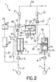
- FIG. 1 generally and schematically shown at 1 is an apparatus for measuring and monitoring medical fluid flows.
- the apparatus 1 is a flowmeter for anaesthesia treatment, that is an apparatus operative to measure and control the flow rates by volume of a pair of gaseous-state fluids.
- gaseous-state fluids are oxygen and nitrous oxide, the latter being an anaesthetic gas.
- the apparatus 1 incorporates a high-safety mixer device 2 intended, according to the invention, for setting with the utmost precision the mixture ratio of said gases.
- Such gases are fed into the apparatus 1 from respective lines 6 and 7.
- the device 2 is connected, on the one side, to an oxygen supply source 4 via the line 6, and on the other side, to a nitrous oxide supply source 5 via the line 7.
- the device 2 includes a pressure switch 3 comprising a pressure chamber 11 housing an elastic membrane 12 on its interior.
- the chamber 11 has an inlet 13 and an outlet 14, and is connected in the oxygen feed line 6.
- the device 2 further includes a pressure control valve 10 which comprises a chamber 15 having an inlet 16 and an outlet 17 and being connected in the nitrous oxide feed line 7.
- the valve 10 has a plunger 18 and respective shutter 20 which is guided, against the bias of a calibrated spring means 19, inside the chamber 15 for movement toward and away from the chamber outlet 17.
- the plunger 18 is driven by the membrane 12 and controlled directly by the membrane movements via a link schematically indicated by an arrow 22.
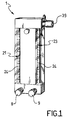
- outlets 14 and 17 of the chambers 11 and 15 are connected to the inlet ends of corresponding flowmeters 21 and 23 of the float valve type, each having a calibrated scale 24. Said outlets are each connected to their respective flowmeters by a corresponding gauged injector as indicated at 26 and 27.
- the device 2 further includes an additional pressure chamber 28 formed by a solid body 32 accomodating an elastic membrane 29 therein.
- a through-going bore 40 is formed in the solid portion of the body 32 which provides an inlet 31 for the chamber 28 connected directly to the outlet 14 of the chamber 11.
- the membrane 29 extends almost across the bottom of the chamber 28 and separates the port formed by the bore 40 from a further inlet 37 of the chamber 28. That inlet 37 is connected directly to the oxygen line 6, upstream of the knob 8, by a bypass line 30.
- an additional safety bypass connection 34 in which a storage tank 35 is connected.
- a sound warning device 36 is also provided on the connection 34, downstream from the tank 35, to warn of any outage in the oxygen pressure.
- the solid portion of the body 32 also has an additional through-going bore 33 extending substantially at right angles, which communicates the bottom of the chamber 28 with an outlet 38 connected to the inlet of the flowmeter 21 via a connection node 41 located downstream from the injector 26 to thereby bypass the injector 26.
- the respective outlets of the flowmeters 21 and 23 are connected to a single gas mixture delivery line 39.
- the oxygen from the supply source 4 is fed into the chamber 11 through the control knob 8.
- the gauged injector 26 is effective to create a load loss in the circuit, and the bore 40 is kept closed by the membrane 29 the pressure force whereof is provided by the pressure of the oxygen admitted upstream of the knob 8 via the bypass line 30.
- the pressure inside the chamber 11 may rise to apply a significant pressure force to the membrane 12.
- the oxygen pressure exerted on the membrane 12 will drive the plunger 18 of that valve 3 to allow the nitrous oxide to leak past the outlet 17 of the chamber 15 to the gauged injector 27, and hence, the flowmeter 23.
- the stroke length of the membrane 12 is limited by a stop, and the nitrous oxide highest flow rate is determined by this stroke end.
- the oxygen will begin to exert a higher pressure force on the membrane 29 in the chamber 28 through the bore 40. This causes the membrane 29 to flex upwards and allows the oxygen to flow, through the bore 33 and the outlet 38 of the chamber 28, into the flowmeter 21 until a maximum flow rate value is achieved as permitted by the passage cross-section of the valve 8.
- the device of this invention has a major advantage in that it enables a mixture to be delivered which contains at all times a proportion of oxygen, thus preventing a patient from being administered pure nitrous oxide in the event of any setting error by the anaesthetist.
- the device of this invention provides for the delivery of nitrous oxide to be automatically cut off in the event of an outage in the oxygen pressure, to thus make the anaesthesia apparatus whereto it is incorporated highly reliable and safe to use.
Landscapes
- Health & Medical Sciences (AREA)
- Emergency Medicine (AREA)
- Pulmonology (AREA)
- Engineering & Computer Science (AREA)
- Anesthesiology (AREA)
- Biomedical Technology (AREA)
- Heart & Thoracic Surgery (AREA)
- Hematology (AREA)
- Life Sciences & Earth Sciences (AREA)
- Animal Behavior & Ethology (AREA)
- General Health & Medical Sciences (AREA)
- Public Health (AREA)
- Veterinary Medicine (AREA)
- Accessories For Mixers (AREA)
- Infusion, Injection, And Reservoir Apparatuses (AREA)
- External Artificial Organs (AREA)
- Mixers With Rotating Receptacles And Mixers With Vibration Mechanisms (AREA)
Claims (5)
- Mischvorrichtung (2) für ein Durchflußmessgerät (1) zum Zusammenmischen von mindestens zwei medizinischen Fluiden, welche jeweils von Zuleitungen (6,7) eingespeist werden, mit- einem Druckschalter (3) mit einer membranartigen (12) Druckkammer (11), die in der Zuleitung (6) des einen Fluids angeschlossen ist,- einem Drucksteuerventil (10), das in der Zuleitung des anderen Fluids angeschlossen ist, mit einer Kammer (15), die einen Einlaß (16) und einen Auslaß (17), einen Plunger (18) und eine entsprechende Verschlußklappe (20) hat, die gegen die Vorspannung einer geeichten Federvorrichtung (19) in Richtung zu dem und weg von dem Auslaß (17) geführt sind, wobei der Plunger (18) mit der Membran verbunden und durch die auf die Membran (12) wirkende Druckkraft gesteuert ist,
gekennzeichnet durch- einen kalibrierten Injektor (26), der mit der Auslaßseite der Druckkammer (11) und der Einlaßseite eines Durchflußmessers (21), der das eine Fluid abgibt, verbunden ist,- eine zweite Druckkammer (28), die eine elastische Membran (29) aufweist und einen ersten Einlaß (37) hat, der mit der Zuleitung (6) des einen Fluids verbunden ist, um den Druckschalter (3) zu umgehen, und einen zweiten Einlaß (31) hat, der mit der Auslaßseite (14) des Druckschalters (3) verbunden und von dem ersten Einlaß (37) durch die Membran (29) getrennt ist,- wobei die zweite Kammer (28) auch einen Auslaß (38) hat, der auf derselben Seite wie der Zweite Einlaß (31) vorgesehen ist und mit dem Durchflußmesser (21) stromabwärts von dem Injektor (26) verbunden ist. - Mischvorrichtung nach Anspruch (1), dadurch gekennzeichnet, daß ferner eine Bypass-Verbindung (34) zwischen der Zuleitung (6) und dem ersten Einlaß (37) der zweiten Kammer (28) vorgesehen ist, wobei die Verbindung (34) einen Speichertank (35) umfaßt.
- Mischvorrichtung nach Anspruch (2), dadurch gekennzeichnet, daß eine Ton-Warnvorrichtung (36) an der Verbindung (34) stromabwärts von dem Tank (35) vorgesehen ist, um bei einem Ausfall des einen Fluiddruckes zu warnen.
- Mischvorrichtung nach Anspruch 1, dadurch gekennzeichnet, daß die Druckkammer (28) in einem Vollkörper (32) ausgebildet ist, der auch die elastische Membran (29) aufnimmt, wobei eine Durchgangsbohrung (40) in dem festen Abschnitt des Körpers (32) ausgebildet ist, um den ersten Einlaß (31) der zweiten Kammer (28) vorzusehen.
- Mischvorrichtung nach Anspruch 1, dadurch gekennzeichnet, daß das Drucksteuerventil (10) einen Auslaß (17) aufweist, der mit einem entsprechenden Einlaß eines zweiten Durchflußmessers (23) über einen zugeordneten kalibrierten Injektor (27) verbunden ist.
Priority Applications (1)
| Application Number | Priority Date | Filing Date | Title |
|---|---|---|---|
| AT89117486T ATE99554T1 (de) | 1988-12-28 | 1989-09-21 | Hochsicherheitsmischer zur verwendung in einem mess- und steuergeraet fuer medizinische fluessigkeiten. |
Applications Claiming Priority (2)
| Application Number | Priority Date | Filing Date | Title |
|---|---|---|---|
| IT2312688 | 1988-12-28 | ||
| IT8823126A IT1227740B (it) | 1988-12-28 | 1988-12-28 | Dispositivo miscelatore di massima sicurezza per una apparecchiatura di misura e controllo di fluidi medicali |
Publications (3)
| Publication Number | Publication Date |
|---|---|
| EP0375845A2 EP0375845A2 (de) | 1990-07-04 |
| EP0375845A3 EP0375845A3 (de) | 1991-02-27 |
| EP0375845B1 true EP0375845B1 (de) | 1994-01-05 |
Family
ID=11204067
Family Applications (1)
| Application Number | Title | Priority Date | Filing Date |
|---|---|---|---|
| EP89117486A Expired - Lifetime EP0375845B1 (de) | 1988-12-28 | 1989-09-21 | Hochsicherheitsmischer zur Verwendung in einem Mess- und Steuergerät für medizinische Flüssigkeiten |
Country Status (5)
| Country | Link |
|---|---|
| EP (1) | EP0375845B1 (de) |
| AT (1) | ATE99554T1 (de) |
| DE (1) | DE68912102T2 (de) |
| ES (1) | ES2047635T3 (de) |
| IT (1) | IT1227740B (de) |
Families Citing this family (1)
| Publication number | Priority date | Publication date | Assignee | Title |
|---|---|---|---|---|
| DE4105972C2 (de) * | 1991-02-26 | 1999-06-02 | Draegerwerk Ag | Narkosemitteldosiervorrichtung |
Family Cites Families (4)
| Publication number | Priority date | Publication date | Assignee | Title |
|---|---|---|---|---|
| DE2250174A1 (de) * | 1972-10-13 | 1974-04-18 | Draegerwerk Ag | Gasmischgeraet fuer druckgase, insbesondere fuer atmungs- und medizinische geraete |
| FR2203481A5 (de) * | 1972-10-16 | 1974-05-10 | Minerve Sa | |
| US4237813A (en) * | 1977-07-22 | 1980-12-09 | Howison Ronald G | Warning and protective device |
| JPS6090568A (ja) * | 1983-10-25 | 1985-05-21 | シチズン時計株式会社 | 麻酔器用流量制御装置 |
-
1988
- 1988-12-28 IT IT8823126A patent/IT1227740B/it active
-
1989
- 1989-09-21 AT AT89117486T patent/ATE99554T1/de not_active IP Right Cessation
- 1989-09-21 EP EP89117486A patent/EP0375845B1/de not_active Expired - Lifetime
- 1989-09-21 DE DE89117486T patent/DE68912102T2/de not_active Expired - Lifetime
- 1989-09-21 ES ES89117486T patent/ES2047635T3/es not_active Expired - Lifetime
Also Published As
| Publication number | Publication date |
|---|---|
| ATE99554T1 (de) | 1994-01-15 |
| DE68912102D1 (de) | 1994-02-17 |
| IT1227740B (it) | 1991-05-06 |
| EP0375845A3 (de) | 1991-02-27 |
| EP0375845A2 (de) | 1990-07-04 |
| ES2047635T3 (es) | 1994-03-01 |
| DE68912102T2 (de) | 1994-05-05 |
| IT8823126A0 (it) | 1988-12-28 |
Similar Documents
| Publication | Publication Date | Title |
|---|---|---|
| US5159924A (en) | Method and apparatus for selectively mixing gases | |
| US4702240A (en) | Demand-responsive gas blending system for medical ventilator | |
| US4142523A (en) | Flow control device for the intravenous administration of liquids | |
| US4549563A (en) | Gas mixers | |
| KR100692290B1 (ko) | 살균수의 제조장치 | |
| EP1960026B1 (de) | Gasmischer mit hilfsmischgasausgang | |
| EP2489392B1 (de) | Gasmischgerät und Verfahren zum Mischen von mindestens zwei verschiedenen Gasen | |
| EP0685238B1 (de) | Gasmischer | |
| US3853144A (en) | Flowmeter | |
| US3528418A (en) | Anesthetic vaporizing apparatus | |
| CA1138669A (en) | Flowmeter with pressure release | |
| US3693653A (en) | Fluid mixing regulator | |
| US4015617A (en) | Analgesic apparatus | |
| US6718980B2 (en) | Treatment of carbon monoxide poisoning | |
| US3848617A (en) | Means for maintaining a fixed flow through a breathing regulator in an inhalation system | |
| US4061160A (en) | Control valve | |
| US3351057A (en) | Patient safeguarding anesthesia apparatus | |
| EP0375845B1 (de) | Hochsicherheitsmischer zur Verwendung in einem Mess- und Steuergerät für medizinische Flüssigkeiten | |
| US4972831A (en) | Gas ratio controlling device for anesthetic appliances | |
| US5885532A (en) | Burette apparatus | |
| JPH02134162A (ja) | 新鮮ガス給気装置 | |
| US6230666B1 (en) | Vaporizer | |
| GB1571023A (en) | Gas mixing apparatus | |
| US3797524A (en) | Fluid metering device | |
| US4294246A (en) | Flow control device for administration of intravenous fluids |
Legal Events
| Date | Code | Title | Description |
|---|---|---|---|
| PUAI | Public reference made under article 153(3) epc to a published international application that has entered the european phase |
Free format text: ORIGINAL CODE: 0009012 |
|
| AK | Designated contracting states |
Kind code of ref document: A2 Designated state(s): AT BE CH DE ES FR GB GR IT LI LU NL SE |
|
| PUAL | Search report despatched |
Free format text: ORIGINAL CODE: 0009013 |
|
| AK | Designated contracting states |
Kind code of ref document: A3 Designated state(s): AT BE CH DE ES FR GB GR IT LI LU NL SE |
|
| 17P | Request for examination filed |
Effective date: 19910207 |
|
| 17Q | First examination report despatched |
Effective date: 19920810 |
|
| GRAA | (expected) grant |
Free format text: ORIGINAL CODE: 0009210 |
|
| AK | Designated contracting states |
Kind code of ref document: B1 Designated state(s): AT BE CH DE ES FR GB GR IT LI LU NL SE |
|
| PG25 | Lapsed in a contracting state [announced via postgrant information from national office to epo] |
Ref country code: IT Free format text: LAPSE BECAUSE OF FAILURE TO SUBMIT A TRANSLATION OF THE DESCRIPTION OR TO PAY THE FEE WITHIN THE PRESCRIBED TIME-LIMIT;WARNING: LAPSES OF ITALIAN PATENTS WITH EFFECTIVE DATE BEFORE 2007 MAY HAVE OCCURRED AT ANY TIME BEFORE 2007. THE CORRECT EFFECTIVE DATE MAY BE DIFFERENT FROM THE ONE RECORDED. Effective date: 19940105 Ref country code: GR Free format text: LAPSE BECAUSE OF FAILURE TO SUBMIT A TRANSLATION OF THE DESCRIPTION OR TO PAY THE FEE WITHIN THE PRESCRIBED TIME-LIMIT Effective date: 19940105 Ref country code: NL Effective date: 19940105 |
|
| REF | Corresponds to: |
Ref document number: 99554 Country of ref document: AT Date of ref document: 19940115 Kind code of ref document: T |
|
| REF | Corresponds to: |
Ref document number: 68912102 Country of ref document: DE Date of ref document: 19940217 |
|
| REG | Reference to a national code |
Ref country code: ES Ref legal event code: FG2A Ref document number: 2047635 Country of ref document: ES Kind code of ref document: T3 |
|
| ET | Fr: translation filed | ||
| NLV1 | Nl: lapsed or annulled due to failure to fulfill the requirements of art. 29p and 29m of the patents act | ||
| PG25 | Lapsed in a contracting state [announced via postgrant information from national office to epo] |
Ref country code: LU Free format text: LAPSE BECAUSE OF NON-PAYMENT OF DUE FEES Effective date: 19940930 |
|
| PLBE | No opposition filed within time limit |
Free format text: ORIGINAL CODE: 0009261 |
|
| STAA | Information on the status of an ep patent application or granted ep patent |
Free format text: STATUS: NO OPPOSITION FILED WITHIN TIME LIMIT |
|
| 26N | No opposition filed | ||
| EAL | Se: european patent in force in sweden |
Ref document number: 89117486.4 |
|
| REG | Reference to a national code |
Ref country code: GB Ref legal event code: IF02 |
|
| PGFP | Annual fee paid to national office [announced via postgrant information from national office to epo] |
Ref country code: ES Payment date: 20080924 Year of fee payment: 20 Ref country code: CH Payment date: 20080826 Year of fee payment: 20 |
|
| PGFP | Annual fee paid to national office [announced via postgrant information from national office to epo] |
Ref country code: AT Payment date: 20080825 Year of fee payment: 20 |
|
| PGFP | Annual fee paid to national office [announced via postgrant information from national office to epo] |
Ref country code: GB Payment date: 20080827 Year of fee payment: 20 |
|
| PGFP | Annual fee paid to national office [announced via postgrant information from national office to epo] |
Ref country code: DE Payment date: 20081002 Year of fee payment: 20 |
|
| PGFP | Annual fee paid to national office [announced via postgrant information from national office to epo] |
Ref country code: SE Payment date: 20080826 Year of fee payment: 20 Ref country code: BE Payment date: 20080829 Year of fee payment: 20 |
|
| PGFP | Annual fee paid to national office [announced via postgrant information from national office to epo] |
Ref country code: FR Payment date: 20080929 Year of fee payment: 20 |
|
| BE20 | Be: patent expired |
Owner name: *FLOW-METER S.P.A. Effective date: 20090921 |
|
| REG | Reference to a national code |
Ref country code: CH Ref legal event code: PL |
|
| REG | Reference to a national code |
Ref country code: GB Ref legal event code: PE20 Expiry date: 20090920 |
|
| EUG | Se: european patent has lapsed | ||
| REG | Reference to a national code |
Ref country code: ES Ref legal event code: FD2A Effective date: 20090922 |
|
| PG25 | Lapsed in a contracting state [announced via postgrant information from national office to epo] |
Ref country code: GB Free format text: LAPSE BECAUSE OF EXPIRATION OF PROTECTION Effective date: 20090920 |
|
| PG25 | Lapsed in a contracting state [announced via postgrant information from national office to epo] |
Ref country code: ES Free format text: LAPSE BECAUSE OF EXPIRATION OF PROTECTION Effective date: 20090922 |