EP0375813A1 - Appareil pour la fabrication d'envois postaux ou d'enveloppes similaires - Google Patents
Appareil pour la fabrication d'envois postaux ou d'enveloppes similaires Download PDFInfo
- Publication number
- EP0375813A1 EP0375813A1 EP88312411A EP88312411A EP0375813A1 EP 0375813 A1 EP0375813 A1 EP 0375813A1 EP 88312411 A EP88312411 A EP 88312411A EP 88312411 A EP88312411 A EP 88312411A EP 0375813 A1 EP0375813 A1 EP 0375813A1
- Authority
- EP
- European Patent Office
- Prior art keywords
- envelope
- intermediate element
- folding
- blank
- continuous sheet
- Prior art date
- Legal status (The legal status is an assumption and is not a legal conclusion. Google has not performed a legal analysis and makes no representation as to the accuracy of the status listed.)
- Granted
Links
- 238000004519 manufacturing process Methods 0.000 title claims abstract description 11
- 230000000712 assembly Effects 0.000 title claims abstract description 8
- 238000000429 assembly Methods 0.000 title claims abstract description 8
- 238000007789 sealing Methods 0.000 claims description 34
- 230000003313 weakening effect Effects 0.000 claims description 21
- 239000012790 adhesive layer Substances 0.000 claims description 10
- 239000010410 layer Substances 0.000 claims description 8
- 230000014759 maintenance of location Effects 0.000 claims description 5
- 239000000853 adhesive Substances 0.000 description 10
- 238000000034 method Methods 0.000 description 9
- 230000003213 activating effect Effects 0.000 description 2
- 230000002411 adverse Effects 0.000 description 2
- 230000009172 bursting Effects 0.000 description 2
- 229920002472 Starch Polymers 0.000 description 1
- 238000001514 detection method Methods 0.000 description 1
- 238000010586 diagram Methods 0.000 description 1
- 230000000694 effects Effects 0.000 description 1
- 238000010438 heat treatment Methods 0.000 description 1
- 238000003780 insertion Methods 0.000 description 1
- 230000037431 insertion Effects 0.000 description 1
- 230000003287 optical effect Effects 0.000 description 1
- 238000003825 pressing Methods 0.000 description 1
- 235000019698 starch Nutrition 0.000 description 1
- 239000008107 starch Substances 0.000 description 1
- 230000009897 systematic effect Effects 0.000 description 1
Images


Classifications
-
- B—PERFORMING OPERATIONS; TRANSPORTING
- B31—MAKING ARTICLES OF PAPER, CARDBOARD OR MATERIAL WORKED IN A MANNER ANALOGOUS TO PAPER; WORKING PAPER, CARDBOARD OR MATERIAL WORKED IN A MANNER ANALOGOUS TO PAPER
- B31B—MAKING CONTAINERS OF PAPER, CARDBOARD OR MATERIAL WORKED IN A MANNER ANALOGOUS TO PAPER
- B31B70/00—Making flexible containers, e.g. envelopes or bags
- B31B70/74—Auxiliary operations
- B31B70/88—Printing; Embossing
-
- B—PERFORMING OPERATIONS; TRANSPORTING
- B31—MAKING ARTICLES OF PAPER, CARDBOARD OR MATERIAL WORKED IN A MANNER ANALOGOUS TO PAPER; WORKING PAPER, CARDBOARD OR MATERIAL WORKED IN A MANNER ANALOGOUS TO PAPER
- B31B—MAKING CONTAINERS OF PAPER, CARDBOARD OR MATERIAL WORKED IN A MANNER ANALOGOUS TO PAPER
- B31B2150/00—Flexible containers made from sheets or blanks, e.g. from flattened tubes
-
- B—PERFORMING OPERATIONS; TRANSPORTING
- B31—MAKING ARTICLES OF PAPER, CARDBOARD OR MATERIAL WORKED IN A MANNER ANALOGOUS TO PAPER; WORKING PAPER, CARDBOARD OR MATERIAL WORKED IN A MANNER ANALOGOUS TO PAPER
- B31B—MAKING CONTAINERS OF PAPER, CARDBOARD OR MATERIAL WORKED IN A MANNER ANALOGOUS TO PAPER
- B31B2160/00—Shape of flexible containers
- B31B2160/10—Shape of flexible containers rectangular and flat, i.e. without structural provision for thickness of contents
-
- B—PERFORMING OPERATIONS; TRANSPORTING
- B31—MAKING ARTICLES OF PAPER, CARDBOARD OR MATERIAL WORKED IN A MANNER ANALOGOUS TO PAPER; WORKING PAPER, CARDBOARD OR MATERIAL WORKED IN A MANNER ANALOGOUS TO PAPER
- B31B—MAKING CONTAINERS OF PAPER, CARDBOARD OR MATERIAL WORKED IN A MANNER ANALOGOUS TO PAPER
- B31B2170/00—Construction of flexible containers
- B31B2170/20—Construction of flexible containers having multi-layered walls, e.g. laminated or lined
Definitions
- the present invention relates to an apparatus for manufacturing sealed postal mails or other sealed envelope assemblies each having a see-through window.
- the present invention relates to such an apparatus for manufacturing sealed postal mails and like envelope assemblies containing intermediate elements that remain free after completing the folding and sealing of envelopes wherein the apparatus processes such envelopes that can be cut off from a continuous sheet along the transverse folding line and folded into three parts (three parts comprising front layer, rear layer and sealing flap) at the transverse folding lines and also processes such discrete intermediate elements to be cut off from the continuous sheet or such as the one to be folded at least along a folding line.
- the present invention relates to an apparatus for manufacturing sealed postal mails and like envelope assemblies, which first bursts a continuous sheet before forming transverse. double-folded envelope blank having a sealing flap in the lengthwise direction, and in conjunction with envelope-sealing process, the apparatus groups and gathers intermediate elements and inserting elements containing preliminarily processed data to be sent to each addressee, and in addition, it also groups those intermediate elements and inserting elements which are to be added selectively before the apparatus eventually inserts these elements between the transverse double-folded blank of the envelope-forming body.
- the invention provides a novel apparatus for processing envelope blanks, intermediate elements and inserting elements, while the apparatus related to the invention properly deals with diversified information to be conveyed by inserted documents and envelopes by materialing the following: detection and designation of the amount of intermediate elements by reading and identifying encoded data preliminarily printed on those intermediate elements; collection through grouping of inserting elements according to addresses either on a random basis or on a constant-number basis; and selective collection of inserting elements which are individually and preliminarily prepared according to addresses before eventually inserting these unit papers into each envelope.
- Another object of the present invention is to provide such a processing unit for the continuous mail sealing, which is suited for the line-printer process using a computer and in addition being particularly effective for the non-impact printing process using heat wherein it comprises such means for concentrically printing information onto a continuous sheet using a computer, while the printable continuous sheet is completely free from the heat-sensitive adhesive layer, and conversely, the heat-sensitive adhesive layer is provided only on the other continuous sheet available for envelopes.
- a still further object of the present invention is to provide such a processing unit for the continuous mail sealing wherein it comprises such means for manufacturing sealed envelopes from which the inserted paper can be easily and immediately drawn out by opening at least one side of an envelope, while the sealed envelope contains the intermediate elements and inserting elements between the front and rear covers, allowing no part of the inserted elements to adhere to the interior of the sealed envelope.
- the present invention relates to such an apparatus that manufactures the sealed postal mails or the like envelope assemblies using a discrete envelope blanks split from an envelope forming continuous sheet, an intermediate element split from an intermediate element-forming continuous and having sizes adapted to be enclosed within the envelope blank.
- the envelope-forming continuous sheet having transverse weakening lines at regular intervals formed to define an envelope blank section between each adjoining two of the weakening lines, each of the envelope blank section having first and second transverse folding lines, a first area for forming the front layer of an envelope defined by first and second transverse folding lines, a sceond area for forming the rear layer of the envelope connected to the first area via the second transverse folding line, a third area for forming the sealing flap of the envelope connected to the first area via the first transverse folding line, a first adhesive layer formed on one surface of the envelope blank section along each of the opposite side edges in direction of the length of the envelope blank section, and a second adhesive layer formed on the same one surface of the envelope blank at the third area.
- the intermediate element-forming continuous sheet having transverse weakening lines at regular intervals formed to define an intermediate element section between each adjoining two of the weakening lines.
- Each of the intermediate element sections having its own specific information printed to be sent to addressee and each of the intermediate element sections further having thereon an encoded mark printed for indicating the number of sheets to be enclosed together when the intermediate element section is followed by at least one intermediate element which is to be sent to the same addressee.
- the apparatus embodied by the invention substantially consists of the following:
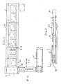
- the sealed mail manufacturing apparatus embodied by the present invention is designed to continuously make up envelope units (E.U) by individually feeding the following into the apparatus; discrete envelopes (72) split from a continuous sheet (71) available for envelopes, discrete intermediate elements (92) made from intermediate-forming continuous sheet (91) available for intermediate elements and additional inserting elements (101) selectively insertable as required.
- An example of the envelope forming continous sheet (71) is shown in Fig. 4.
- This envelope forming continuous sheet (71) is provided with marginal perforation lines (73) and (73) along opposite edges in the direction of its length and also with the marginal perforation split lines (74) and (74) so that the marginal perforation lines (73) and (73) can be cut off along the internal line of these lines (73) and (73).
- Said envelope-forming continuous sheet (71) is provided with tearable transverse weakening line (75) at regular interval in the direction of length, thus defining the area available for the discrete envelope blank (72).
- the envelope blank (72) sectioned by said transverse weakening line (75) is provided with the first folding line (76) and the second folding line (77) in parallel with said transverse weakening line (75).
- the envelope blank (72) is also provided with sealing flap (78) formed between the transverse weakening line (75) and the first holding line (76), front area (79) formed between the first folding line (76) and the second folding line (77), and the rear area (80) formed between the second folding line (77) and the transverse weakening line (75).
- Length (LA) in the lengthwise direction of the front area (79) substantially constitutes one side (a short side of the envelope of the envelope shown in Fig. 4) of the envelope itself.
- the length (LA′) in the lengthwise direction of the rear area (80) is slightly shorter than (LA).
- the dimension (LA) and (LB) of the sealed envelope unit (EU) is optionally chosen, i.e. the dimension may be LA ⁇ LB as shown in the illustrated preferred embodiment, or it may conversely be LA ⁇ LB.
- the envelope blank of the continuous sheet (71) is provided with the first and second adhesive-agent coated zones (81) and (82) for sealing the envelope itself in the direction of folding the second folding line (77) into inner surface (71a).
- the first adhesive-agent coated zones (81),(81) are respectively formed in parallel with each other along the inner edge of said marginal perforation split lines (74), (74), whereas the second adhesive-agent coated zones (82),(82) are respectively formed in the direction of traversing the sealing flap (78).
- Either thermally pressing type adhesive agent, or pressure-applied adhesive agent, or water-soluble starch may also be used for making up those adhesive-agent coated zones (81) and (82).
- an isosceles triangular diecut (83) is provided in conjunction with the transverse weakening line (75) and the marginal perforation split line (74). Ihe length of each side of isosceles forming the diecut (83) almost matches the length of the sealing flap (78).
- Portion (79) making up the front area of the envelope-forming continuous sheet (71) is provided with a see-through window (84) at an optional location.
- Such a see-through window (84) may be formed by bonding a transparent sheet (86) to the opening (85) on the front area (79) from the inner surface (71a) of the envelope-forming continuous sheet (71) using adhesive agent for example.
- the see-through window (84) may be of such a constitution which allows only limited portion of information (i.e., address and addressee) written on the inserted document to be externally visible.
- Perforated line (87) shown in Fig. 4 used for opening the sealed envelope is provided in parallel with the inner edge of either of the first adhesive-agent coated zones (81) and (81).
- Fig. 5-A, -B, -C and -D respectively denote styles of a variety of continuous sheets (91) for the intermediate elements to be inserted into envelopes. Each of those continuous sheets (91) is used for making up intermediate elements.
- Those continuous sheets (91A), (91B), (91C) and (91D) are respectively provided with marginal perforation lines (93) and (93) along both sides and in the lengthwise direction.
- these continuous sheets (91A), (91B), (91C) and (91D) are also provided with split lines (94) and (94) to cut off those marginal perforation lines (93) and (93) along the inner side of these perforation lines.
- 5-D continuously forms a cross-folding (triple folding in the transversal direction and double-folding in the longitudinal direction) intermediate element (92D) having the central folding line (97) in the lengthwise direction and a pair of transverse folding lines (96) and (96) between transverse weakening lines (95) and (95).
- side length (La) of each of these intermediate elements (92A), (92B), (92C) and (92D) is slightly shorter than the length (LA) of the sealed envelope unit (EU), and likewise, the other side length (Lb) is also slightly shorter than the inner length of the first adhesive-agent coated zones (81) and (81) of the sealed envelope unit (EU).
- Identification encoded mark (99) is preliminarily printed on each of these intermediate element-forming continuous sheets (91A), (91B), (91C) and (91D) in order that intermediate elements can properly be grouped and gathered according to addresses and addressees.
- the identification encode mark (99) is provided for each unit of intermediate element (92) and composed of 7-bit bar code for example.
- the identification encode mark (99) is read and identified by an encode-mark sensor set to the apparatus related to the invention, and based on the identified encode mark, instructions are generated to group and gather intermediate elements (92) as per addresses and addressees, selectively insert additional inserting elements (101), and divert the non-printed intermeidate elements.
- Fig. 6-A, -B and -C respectively denote examples of a variety of additional inserting elements (101). These elements (101) are not split from a continuous sheet, but each of these elements (101) consists of either a single leaf (101A) or a preliminarily folded and cut sheet (101B) or (101C) for example.
- Fig 6-A represents a single-leaf additional inserting element (101A).
- Fig. 6-B represents a transverse double-folded additional inserting element (101B) having a transversely folding line (102).
- Fig. 6-C represents a transverse triple-folded additional inserting element (101C) having a pair of transverse folding lines (102) and (102).
- the intermediate-element supplying system (1) is composed of stocker (2) which stocks the intermediate-element forming continuous sheet (91), separating means (3) which separates the continuous sheet (91) into intermediate element (92), and the feeding means (4) which feeds intermediate element, respectively.
- stocker (2) which stocks the intermediate-element forming continuous sheet (91)
- separating means (3) which separates the continuous sheet (91) into intermediate element (92)
- feeding means (4) which feeds intermediate element, respectively.
- the intermediate-element forming continuous sheet (91) shown in Fig. 5 is split into intermediate elements by the separating means (3) which is provided with marginal slitter (6) and bursting device (7).
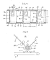
- transverse-folding means (10) which is composed of intermediate-element introducing guide member (11), insertable-intermediate-element forwarding guide member (12), the first through fourth rollers (13) through (16), and the first and second guide stoppers (17) and (18), respectively.
- Guide stoppers (17) and (18) are respectively provided with stoppers (19) and (20) which adjust their positions to stop the movement of the intermediate elements (92).
- Each of intermediate elements (92) is led between a pair of rollers (13) and (14) along the introduction guide member (11) before being led to the first guide stopper (17) by rollers (13) and (14).
- Each of intermediate elements (92) bends itself at the inlet portion of rollers (13) and (15) with its tip edge being in contact with stopper (19) and then the insertable paper itself is pressed by rollers (13) and (15) before eventually being folded transversely.
- Transverse double-folded intermediate element (92A) shown in Fig. 5-A dispenses with the secondary folding otherwise to be done in the transversal direction.
- intermediate element sertable paper (92) is then directly led by guide member (21) provided in place of the guide stopper (18) so that the intermediate element (92) can pass through rollers (13) and (16) before being discharged to the feeding line.
- Those intermediate elements (92C) and(92D ) each having a longitudinal folding line shown in Fig. 5-C and 5-D are preliminarily provided with vertical folding process by the longitudinal folding unit (not shown).
- the transverse folding means (10) turns the fed intermediate element (92) upside down using guide member (21).
- the distance between stopper (19) of the first guide stopper (17) and rollers (13) and (14) is extended in order that the distance can be longer than the length of the intermediate element (92) itself.
- the intermediate element (92) carried into the first guide stopper (17) is then delivered to a pair of rollers (13) and (15) by a pair of back rollers (B.R).
- additional inserting-element feeding means (22) is provided.
- This means (22) is provided with the first and second feeding units (23) and (24) for example, which respectively insert printed papers into envelopes.
- the apparatus related to the invention is provided with paper grouping and collecting means (25), which first reads and identifies encode marks printed on the intermediate elements, and then stores those intermediate elements by each inserting unit.
- this grouping means (25) selectively adds additional inserting elements stored in the additional inserting element feeding means (22) to the original intermediate element (92), and finally, it groups and collects those intermediate elemenets according to addresses and addressees.
- the paper grouping and collecting means (25) is provided with function for randomly collecting intermediate elements, precisely collecting intermediate elements by the predetermined number, and selectively inserting additional elements into each envelope, respectively.
- the OMR sensor reads and identifies the encode marks on the intermediate elements according to the predetermined rule, and then, acting on the instruction signal, grouping and collection of intermediate elements by random number can be executed. Grouping and collection of the intermediate elements by the predetermined number can be executed without referring to encode marks on those elements, but merely by inserting a specific number of those intermediate elements of each lot.
- a specific mechanism having two of the additional inserting element feeding means when activating function for selectively inserting additional inserting elements, a specific mechanism having two of the additional inserting element feeding means generates instructions for selecting any of four functional operations including delivery of the first and second additional inserting elements, executing independent delivery of only the first additional inserting elements and only the second additional inserting elements, and with holding delivery of both the first and second additional inserting elements, respectivey. All of these instructions are generated as a result of reading and identifying encode marks on each of intermediate elements (92).
- the apparatus related to the invention feeds additional inserting elements (101) to the original intermediate element (92). Both the grouped original intermediate elements (92) and additional inserting elements (101) are then delivered to the inserting-unit delivery means (26).
- Said intermediate element feeder (26) is predetermined to feed said intermediate element in supply velosity (V2) to said envelope folding and intermediate element inserting station (E.S.).
- the second sensor (S2) and the second gate (G2) is provided.
- Said second sensor (S2) outputs the detecting signal (e2) when detecting said intermediate elements at the intermediate element feeder (26).
- Said second gate (G2) is provided at the feed track of said intermediate element feeder (26), with the object of aligning the tip-end of said group of intermediate elements.
- Said second gate (G2) is predetermined to open in response to said detecting signal (e2) from said second sensor (S2) when said tip-end of said intermediate elements at said second gate (G2).
- the paper-forwarding roller (28) classifies and collects each of intermediate element and inserting elements, and finally, it forwards each of the grouped inserting unit in order that each of these can come into contact with the second folding line (77) of the envelope blank (72).
- the apparatus related to the invention is also provided with envelope-blank supplying system (30) which first activates separating means (29) to separate the envelope-forming continuous sheet (71) into individual envelope blanks (72) and then conveys these envelope blanks (72) to the inserting station (E.S). Discrete envelope blank (72) is then fed to the predetermined inserting station (E.S) by feeding means (31).
- the inserting station (E.S) is provided with the envelope-blank holder means (27). This holder means holds the envelope blank (72) almost at right angle against the intermediate elements (92) which are horizontally forwarded by the intermediate element delivery means (26).
- the envelope-blank holder means (27) aligns the position of the second transverse folding line (77) of the envelope blank (72) in order that the transverse folding line (77) can correctly match the paper-inserting line. This allows each envelope blank (72) to be held at standby posture at the predetermined position.
- Said envelope blank feeder (30) is predetermined to feed said envelope blank in supply velosity (V1) to said envelope folding and intermediate element inserting station (E.S.).
- Said supply velosity (V1) of said envelope blank being greater than said supply velosity (V2) of said intermediate element, so that envelope blank (72) is predetermined to wait at said envelope blank folding and intermediate element inserting station (E.S.).
- the first sensor (S1) and the first gate (G1) is provided.
- Said first sensor (S1) outputs the detecting signal (e1) when sensing in the absence of said envelope blank retention means (27).
- Said first gate (G1) is provided at the feed track of said envelope blank feeder (30), with the object of intermittently feeding one by one said envelope blank.
- Said first gate (G1) is predetermined to open in response to said detecting signal (e1) from said first sensor (S1).
- folding roller means (32) is installed to the rear stage of the envelope-blank holder means (27).
- the folding roller means (32) is composed of a pair of rollers (34) and (34) to allow the inlet aperture (33) to open itself in order that these rollers (34) and (34) correctly align the second transverse folding line (77) of the envelope blank (72) with the aperture (33).
- the envelope blank (72) is folded along the second transverse folding line (77), and then, the envelope blank (72) is led into the rear-stage rollers (34) and (34) before eventually being folded when passing through rollers (34) and (34).
- the first sealing means (35) is installed to the rear stage of the folding roller means (32).
- the first sealing means (35) is composed of a pair of heaters (36) and (36) and pressurized conveyer belt (37).
- Heaters (36) and (36) are respectively installed along the predetermined path of the first adhesive-agent coated zones (81) and (81) of the envelope-body, i.e., in the manner of facing both sides of the envelope in the forwarding direction.
- Each envelope with both sides being fused by the first sealing mechanism (35) is then led into the movement-path changing means (38) to allow either of the fused sides to precede by changing the direction of the movement of envelope by 90 degrees.
- the envelope body is delivered to the flap enveloping unit (F.E) which is provided with the flap-folding means (39) and the second sealing means (40).
- the flap-enveloping unit (F.E) folds envelope flap (78) along the first transverse folding line (76) before fully sealing the envelope body with the second sealing means (40).
- each of the completely sealed envelopes is conveyed to the following workshop via the delivery unit (41) according to purposes.
- the apparatus When automatically inserting and enveloping documents or the like into individual envelopes by operating the automatic envelope and insertable paper processing apparatus embodied by the invention featuring the novel constitution thus far described, by virtue of reading and identifying encode marks preliminarily printed on each of intermediate elements and inserting elements, the apparatus can correctly detect and instruct the amount of papers to be inserted into each envelope before effectively classifying these papers and envelopes according to addressees.
- the grouping operation of envelope-intermediate elements can be executed either randomly or on the basis of constant number, and yet, whenever necessity arises, the apparatus related to the invention selectively classifies and collects each of preliminarily prepared additional inserting elements before fully enclosing them as a unit into the designated envelopes.
- the envelope and intermediate element processing apparatus related to the invention changes the direction of feeding each envelope by 90 degrees before fully sealing envelope bodies.
- the apparatus discretely uses different heater units for thermally sealing each envelope along the vertical and lateral edges so that thermal sealing can locally be achieved. This effectively prevents the paper-inserted portion of each envelope from adversely being affected by heating and pressurized effect, thus totally eliminating adverse influence otherwise incurring to the enclosed computer-processed printed documents.
Landscapes
- Making Paper Articles (AREA)
- Supplying Of Containers To The Packaging Station (AREA)
- Jellies, Jams, And Syrups (AREA)
- Packaging Of Special Articles (AREA)
Priority Applications (4)
| Application Number | Priority Date | Filing Date | Title |
|---|---|---|---|
| AT88312411T ATE90270T1 (de) | 1988-12-29 | 1988-12-29 | Apparat fuer die fertigung verschlossener postsendungen oder aehnlicher umschlaege. |
| DE88312411T DE3881701T2 (de) | 1988-12-29 | 1988-12-29 | Apparat für die Fertigung verschlossener Postsendungen oder ähnlicher Umschläge. |
| ES88312411T ES2042777T3 (es) | 1988-12-29 | 1988-12-29 | Aparato para confeccionar valijas postales precintadas y otros conjuntos de envolturas similares. |
| EP88312411A EP0375813B1 (fr) | 1988-12-29 | 1988-12-29 | Appareil pour la fabrication d'envois postaux ou d'enveloppes similaires |
Applications Claiming Priority (1)
| Application Number | Priority Date | Filing Date | Title |
|---|---|---|---|
| EP88312411A EP0375813B1 (fr) | 1988-12-29 | 1988-12-29 | Appareil pour la fabrication d'envois postaux ou d'enveloppes similaires |
Publications (2)
| Publication Number | Publication Date |
|---|---|
| EP0375813A1 true EP0375813A1 (fr) | 1990-07-04 |
| EP0375813B1 EP0375813B1 (fr) | 1993-06-09 |
Family
ID=8200337
Family Applications (1)
| Application Number | Title | Priority Date | Filing Date |
|---|---|---|---|
| EP88312411A Expired - Lifetime EP0375813B1 (fr) | 1988-12-29 | 1988-12-29 | Appareil pour la fabrication d'envois postaux ou d'enveloppes similaires |
Country Status (4)
| Country | Link |
|---|---|
| EP (1) | EP0375813B1 (fr) |
| AT (1) | ATE90270T1 (fr) |
| DE (1) | DE3881701T2 (fr) |
| ES (1) | ES2042777T3 (fr) |
Citations (4)
| Publication number | Priority date | Publication date | Assignee | Title |
|---|---|---|---|---|
| US2427839A (en) * | 1944-02-05 | 1947-09-23 | Davidson Mfg Corp | Collator |
| DE3211791A1 (de) * | 1982-03-30 | 1983-10-13 | Leunismann Großdruckerei für Werbung und Verpackung GmbH, 3000 Hannover | Papierverarbeitungsmaschine und verfahren zu deren steuern |
| EP0185811A2 (fr) * | 1984-12-19 | 1986-07-02 | Iseto Shiko Co. Limited | Appareil pour la fabrication d'ensembles d'enveloppes scellées |
| EP0297843A1 (fr) * | 1987-06-30 | 1989-01-04 | Iseto Shiko Co. Limited | Appareil pour manufacturer des envois postaux fermés ou enveloppes similaires |
Family Cites Families (2)
| Publication number | Priority date | Publication date | Assignee | Title |
|---|---|---|---|---|
| DE3312087A1 (de) * | 1983-04-02 | 1984-10-04 | Winkler & Dünnebier, Maschinenfabrik und Eisengießerei GmbH & Co KG, 5450 Neuwied | Verfahren und vorrichtung zum einfuellen von fuellgut in eine huelle |
| EP0372140A1 (fr) * | 1988-12-09 | 1990-06-13 | Iseto Shiko Co. Limited | Appareil pour la fabrication d'envois postaux clos ou d'enveloppes similaires |
-
1988
- 1988-12-29 EP EP88312411A patent/EP0375813B1/fr not_active Expired - Lifetime
- 1988-12-29 ES ES88312411T patent/ES2042777T3/es not_active Expired - Lifetime
- 1988-12-29 DE DE88312411T patent/DE3881701T2/de not_active Expired - Fee Related
- 1988-12-29 AT AT88312411T patent/ATE90270T1/de not_active IP Right Cessation
Patent Citations (4)
| Publication number | Priority date | Publication date | Assignee | Title |
|---|---|---|---|---|
| US2427839A (en) * | 1944-02-05 | 1947-09-23 | Davidson Mfg Corp | Collator |
| DE3211791A1 (de) * | 1982-03-30 | 1983-10-13 | Leunismann Großdruckerei für Werbung und Verpackung GmbH, 3000 Hannover | Papierverarbeitungsmaschine und verfahren zu deren steuern |
| EP0185811A2 (fr) * | 1984-12-19 | 1986-07-02 | Iseto Shiko Co. Limited | Appareil pour la fabrication d'ensembles d'enveloppes scellées |
| EP0297843A1 (fr) * | 1987-06-30 | 1989-01-04 | Iseto Shiko Co. Limited | Appareil pour manufacturer des envois postaux fermés ou enveloppes similaires |
Also Published As
| Publication number | Publication date |
|---|---|
| DE3881701D1 (de) | 1993-07-15 |
| ES2042777T3 (es) | 1993-12-16 |
| EP0375813B1 (fr) | 1993-06-09 |
| ATE90270T1 (de) | 1993-06-15 |
| DE3881701T2 (de) | 1993-10-07 |
Similar Documents
| Publication | Publication Date | Title |
|---|---|---|
| US4972655A (en) | Apparatus for manufacturing sealed postal mails or the like envelope assemblies | |
| US4668211A (en) | Method for preparing a returnable self-mailer | |
| US4915287A (en) | Intelligently imaged envelopes with intelligently imaged integral tear-off flaps | |
| US4733856A (en) | Mechanism for forming personalized envelopes and inserts | |
| EP0297843B1 (fr) | Appareil pour manufacturer des envois postaux fermés ou enveloppes similaires | |
| US4668212A (en) | Process for manufacturing sealed postal envelope assemblies | |
| US5794409A (en) | Method of processing and stuffing an envelope | |
| US5288014A (en) | Two-way mailer | |
| US5049227A (en) | Apparatus having a diverter responsive to jams for preparing a self-mailer | |
| US5192389A (en) | Apparatus for preparing a self-mailer having printer, folder, and transport means | |
| EP0372140A1 (fr) | Appareil pour la fabrication d'envois postaux clos ou d'enveloppes similaires | |
| US5095682A (en) | Mailer and method and apparatus for making | |
| US5064115A (en) | Mailer and method and apparatus for making | |
| CA2005728C (fr) | Dispositif pour constituer des envois postaux cachetes | |
| EP0375813B1 (fr) | Appareil pour la fabrication d'envois postaux ou d'enveloppes similaires | |
| GB2158035A (en) | Method and equipment for automatically inserting encoded cards into a web of envelopes | |
| US5452851A (en) | Two-sheet self-mailer | |
| JP2001505143A (ja) | 枚数にむらのある通信文を自動的に封筒詰めするための機械および方法 | |
| US5573232A (en) | Parallel sheet processing apparatus | |
| KR0134891B1 (ko) | 봉입물 밀봉봉투 가공처리장치 | |
| JP3666284B2 (ja) | 封書作成装置 | |
| JPS6210179B2 (fr) | ||
| CA2025257A1 (fr) | Appareil pour la preparation d'une formule-enveloppe | |
| JPS6389338A (ja) | 窓付封筒加工処理装置 | |
| WO1992000879A1 (fr) | Systeme servant a produire un paquet individualise |
Legal Events
| Date | Code | Title | Description |
|---|---|---|---|
| PUAI | Public reference made under article 153(3) epc to a published international application that has entered the european phase |
Free format text: ORIGINAL CODE: 0009012 |
|
| AK | Designated contracting states |
Kind code of ref document: A1 Designated state(s): AT BE CH DE ES FR GB IT LI NL SE |
|
| 17P | Request for examination filed |
Effective date: 19900717 |
|
| 17Q | First examination report despatched |
Effective date: 19920316 |
|
| GRAA | (expected) grant |
Free format text: ORIGINAL CODE: 0009210 |
|
| AK | Designated contracting states |
Kind code of ref document: B1 Designated state(s): AT BE CH DE ES FR GB IT LI NL SE |
|
| REF | Corresponds to: |
Ref document number: 90270 Country of ref document: AT Date of ref document: 19930615 Kind code of ref document: T |
|
| REF | Corresponds to: |
Ref document number: 3881701 Country of ref document: DE Date of ref document: 19930715 |
|
| ITF | It: translation for a ep patent filed | ||
| ET | Fr: translation filed | ||
| REG | Reference to a national code |
Ref country code: ES Ref legal event code: FG2A Ref document number: 2042777 Country of ref document: ES Kind code of ref document: T3 |
|
| PLBE | No opposition filed within time limit |
Free format text: ORIGINAL CODE: 0009261 |
|
| STAA | Information on the status of an ep patent application or granted ep patent |
Free format text: STATUS: NO OPPOSITION FILED WITHIN TIME LIMIT |
|
| 26N | No opposition filed | ||
| EAL | Se: european patent in force in sweden |
Ref document number: 88312411.7 |
|
| PGFP | Annual fee paid to national office [announced via postgrant information from national office to epo] |
Ref country code: GB Payment date: 20001115 Year of fee payment: 13 |
|
| PGFP | Annual fee paid to national office [announced via postgrant information from national office to epo] |
Ref country code: CH Payment date: 20001120 Year of fee payment: 13 |
|
| PGFP | Annual fee paid to national office [announced via postgrant information from national office to epo] |
Ref country code: NL Payment date: 20001121 Year of fee payment: 13 |
|
| PGFP | Annual fee paid to national office [announced via postgrant information from national office to epo] |
Ref country code: AT Payment date: 20001122 Year of fee payment: 13 |
|
| PGFP | Annual fee paid to national office [announced via postgrant information from national office to epo] |
Ref country code: BE Payment date: 20001130 Year of fee payment: 13 |
|
| PGFP | Annual fee paid to national office [announced via postgrant information from national office to epo] |
Ref country code: SE Payment date: 20001204 Year of fee payment: 13 Ref country code: FR Payment date: 20001204 Year of fee payment: 13 |
|
| PGFP | Annual fee paid to national office [announced via postgrant information from national office to epo] |
Ref country code: DE Payment date: 20001213 Year of fee payment: 13 |
|
| PGFP | Annual fee paid to national office [announced via postgrant information from national office to epo] |
Ref country code: ES Payment date: 20001218 Year of fee payment: 13 |
|
| PG25 | Lapsed in a contracting state [announced via postgrant information from national office to epo] |
Ref country code: GB Free format text: LAPSE BECAUSE OF NON-PAYMENT OF DUE FEES Effective date: 20011229 Ref country code: AT Free format text: LAPSE BECAUSE OF NON-PAYMENT OF DUE FEES Effective date: 20011229 |
|
| PG25 | Lapsed in a contracting state [announced via postgrant information from national office to epo] |
Ref country code: SE Free format text: LAPSE BECAUSE OF NON-PAYMENT OF DUE FEES Effective date: 20011230 |
|
| PG25 | Lapsed in a contracting state [announced via postgrant information from national office to epo] |
Ref country code: LI Free format text: LAPSE BECAUSE OF NON-PAYMENT OF DUE FEES Effective date: 20011231 Ref country code: CH Free format text: LAPSE BECAUSE OF NON-PAYMENT OF DUE FEES Effective date: 20011231 Ref country code: BE Free format text: LAPSE BECAUSE OF NON-PAYMENT OF DUE FEES Effective date: 20011231 |
|
| REG | Reference to a national code |
Ref country code: GB Ref legal event code: IF02 |
|
| BERE | Be: lapsed |
Owner name: ISETO SHIKO CO. LTD Effective date: 20011231 |
|
| PG25 | Lapsed in a contracting state [announced via postgrant information from national office to epo] |
Ref country code: NL Free format text: LAPSE BECAUSE OF NON-PAYMENT OF DUE FEES Effective date: 20020701 |
|
| PG25 | Lapsed in a contracting state [announced via postgrant information from national office to epo] |
Ref country code: DE Free format text: LAPSE BECAUSE OF NON-PAYMENT OF DUE FEES Effective date: 20020702 |
|
| EUG | Se: european patent has lapsed |
Ref document number: 88312411.7 |
|
| REG | Reference to a national code |
Ref country code: CH Ref legal event code: PL |
|
| GBPC | Gb: european patent ceased through non-payment of renewal fee |
Effective date: 20011229 |
|
| PG25 | Lapsed in a contracting state [announced via postgrant information from national office to epo] |
Ref country code: FR Free format text: LAPSE BECAUSE OF NON-PAYMENT OF DUE FEES Effective date: 20020830 |
|
| NLV4 | Nl: lapsed or anulled due to non-payment of the annual fee |
Effective date: 20020701 |
|
| REG | Reference to a national code |
Ref country code: FR Ref legal event code: ST |
|
| PG25 | Lapsed in a contracting state [announced via postgrant information from national office to epo] |
Ref country code: ES Free format text: LAPSE BECAUSE OF NON-PAYMENT OF DUE FEES Effective date: 20021230 |
|
| REG | Reference to a national code |
Ref country code: ES Ref legal event code: FD2A Effective date: 20030113 |
|
| PG25 | Lapsed in a contracting state [announced via postgrant information from national office to epo] |
Ref country code: IT Free format text: LAPSE BECAUSE OF NON-PAYMENT OF DUE FEES;WARNING: LAPSES OF ITALIAN PATENTS WITH EFFECTIVE DATE BEFORE 2007 MAY HAVE OCCURRED AT ANY TIME BEFORE 2007. THE CORRECT EFFECTIVE DATE MAY BE DIFFERENT FROM THE ONE RECORDED. Effective date: 20051229 |