EP0375775B1 - Catheter equipped with balloon - Google Patents
Catheter equipped with balloon Download PDFInfo
- Publication number
- EP0375775B1 EP0375775B1 EP87907823A EP87907823A EP0375775B1 EP 0375775 B1 EP0375775 B1 EP 0375775B1 EP 87907823 A EP87907823 A EP 87907823A EP 87907823 A EP87907823 A EP 87907823A EP 0375775 B1 EP0375775 B1 EP 0375775B1
- Authority
- EP
- European Patent Office
- Prior art keywords
- balloon
- tube
- catheter assembly
- assembly according
- outer tube
- Prior art date
- Legal status (The legal status is an assumption and is not a legal conclusion. Google has not performed a legal analysis and makes no representation as to the accuracy of the status listed.)
- Expired - Lifetime
Links
- 239000000945 filler Substances 0.000 claims description 16
- 238000001802 infusion Methods 0.000 claims description 16
- 210000004369 blood Anatomy 0.000 claims description 10
- 239000008280 blood Substances 0.000 claims description 10
- 230000002093 peripheral effect Effects 0.000 claims description 8
- 239000000126 substance Substances 0.000 claims description 8
- 210000001124 body fluid Anatomy 0.000 claims description 7
- 239000010839 body fluid Substances 0.000 claims description 7
- 239000000463 material Substances 0.000 claims description 7
- 229920002635 polyurethane Polymers 0.000 claims description 7
- 239000004814 polyurethane Substances 0.000 claims description 7
- -1 polyethylene Polymers 0.000 claims description 6
- 229920005989 resin Polymers 0.000 claims description 6
- 239000011347 resin Substances 0.000 claims description 6
- 239000004677 Nylon Substances 0.000 claims description 4
- 239000005038 ethylene vinyl acetate Substances 0.000 claims description 4
- 229920001778 nylon Polymers 0.000 claims description 4
- 229920001200 poly(ethylene-vinyl acetate) Polymers 0.000 claims description 4
- 229920000728 polyester Polymers 0.000 claims description 4
- 229920000915 polyvinyl chloride Polymers 0.000 claims description 4
- 239000004800 polyvinyl chloride Substances 0.000 claims description 4
- 240000007741 Lagenaria siceraria Species 0.000 claims description 3
- 235000009797 Lagenaria vulgaris Nutrition 0.000 claims description 3
- 239000004698 Polyethylene Substances 0.000 claims description 3
- 239000003550 marker Substances 0.000 claims description 3
- 229920000573 polyethylene Polymers 0.000 claims description 3
- 239000004945 silicone rubber Substances 0.000 claims description 3
- 229920000126 latex Polymers 0.000 claims description 2
- 239000004816 latex Substances 0.000 claims description 2
- 239000007788 liquid Substances 0.000 claims description 2
- 229920002379 silicone rubber Polymers 0.000 claims description 2
- 239000004952 Polyamide Substances 0.000 claims 2
- 239000004743 Polypropylene Substances 0.000 claims 2
- 229920002647 polyamide Polymers 0.000 claims 2
- 229920001155 polypropylene Polymers 0.000 claims 2
- 229920000139 polyethylene terephthalate Polymers 0.000 claims 1
- 239000005020 polyethylene terephthalate Substances 0.000 claims 1
- 210000004204 blood vessel Anatomy 0.000 abstract description 13
- 230000014759 maintenance of location Effects 0.000 abstract 1
- 238000000034 method Methods 0.000 description 7
- 239000012266 salt solution Substances 0.000 description 4
- 210000001367 artery Anatomy 0.000 description 2
- TZCXTZWJZNENPQ-UHFFFAOYSA-L barium sulfate Chemical compound [Ba+2].[O-]S([O-])(=O)=O TZCXTZWJZNENPQ-UHFFFAOYSA-L 0.000 description 2
- BASFCYQUMIYNBI-UHFFFAOYSA-N platinum Chemical compound [Pt] BASFCYQUMIYNBI-UHFFFAOYSA-N 0.000 description 2
- 229920000098 polyolefin Polymers 0.000 description 2
- 238000001356 surgical procedure Methods 0.000 description 2
- 229920005992 thermoplastic resin Polymers 0.000 description 2
- 206010010356 Congenital anomaly Diseases 0.000 description 1
- 239000004372 Polyvinyl alcohol Substances 0.000 description 1
- 238000002583 angiography Methods 0.000 description 1
- 230000005540 biological transmission Effects 0.000 description 1
- 229910000416 bismuth oxide Inorganic materials 0.000 description 1
- 230000017531 blood circulation Effects 0.000 description 1
- 230000002490 cerebral effect Effects 0.000 description 1
- TYIXMATWDRGMPF-UHFFFAOYSA-N dibismuth;oxygen(2-) Chemical compound [O-2].[O-2].[O-2].[Bi+3].[Bi+3] TYIXMATWDRGMPF-UHFFFAOYSA-N 0.000 description 1
- 239000013013 elastic material Substances 0.000 description 1
- 238000002594 fluoroscopy Methods 0.000 description 1
- PCHJSUWPFVWCPO-UHFFFAOYSA-N gold Chemical compound [Au] PCHJSUWPFVWCPO-UHFFFAOYSA-N 0.000 description 1
- 229910052737 gold Inorganic materials 0.000 description 1
- 239000010931 gold Substances 0.000 description 1
- 238000012986 modification Methods 0.000 description 1
- 230000004048 modification Effects 0.000 description 1
- 210000005259 peripheral blood Anatomy 0.000 description 1
- 239000011886 peripheral blood Substances 0.000 description 1
- 229910052697 platinum Inorganic materials 0.000 description 1
- 229920001296 polysiloxane Polymers 0.000 description 1
- 229920002451 polyvinyl alcohol Polymers 0.000 description 1
- 229920002631 room-temperature vulcanizate silicone Polymers 0.000 description 1
- 239000007787 solid Substances 0.000 description 1
- KKEYFWRCBNTPAC-UHFFFAOYSA-L terephthalate(2-) Chemical compound [O-]C(=O)C1=CC=C(C([O-])=O)C=C1 KKEYFWRCBNTPAC-UHFFFAOYSA-L 0.000 description 1
- WFKWXMTUELFFGS-UHFFFAOYSA-N tungsten Chemical compound [W] WFKWXMTUELFFGS-UHFFFAOYSA-N 0.000 description 1
- 229910052721 tungsten Inorganic materials 0.000 description 1
- 239000010937 tungsten Substances 0.000 description 1
- 230000002792 vascular Effects 0.000 description 1
Images


Classifications
-
- A—HUMAN NECESSITIES
- A61—MEDICAL OR VETERINARY SCIENCE; HYGIENE
- A61B—DIAGNOSIS; SURGERY; IDENTIFICATION
- A61B17/00—Surgical instruments, devices or methods
- A61B17/12—Surgical instruments, devices or methods for ligaturing or otherwise compressing tubular parts of the body, e.g. blood vessels or umbilical cord
- A61B17/12022—Occluding by internal devices, e.g. balloons or releasable wires
- A61B17/12131—Occluding by internal devices, e.g. balloons or releasable wires characterised by the type of occluding device
- A61B17/12136—Balloons
-
- A—HUMAN NECESSITIES
- A61—MEDICAL OR VETERINARY SCIENCE; HYGIENE
- A61B—DIAGNOSIS; SURGERY; IDENTIFICATION
- A61B17/00—Surgical instruments, devices or methods
- A61B17/12—Surgical instruments, devices or methods for ligaturing or otherwise compressing tubular parts of the body, e.g. blood vessels or umbilical cord
- A61B17/12022—Occluding by internal devices, e.g. balloons or releasable wires
- A61B17/12099—Occluding by internal devices, e.g. balloons or releasable wires characterised by the location of the occluder
- A61B17/12109—Occluding by internal devices, e.g. balloons or releasable wires characterised by the location of the occluder in a blood vessel
-
- A—HUMAN NECESSITIES
- A61—MEDICAL OR VETERINARY SCIENCE; HYGIENE
- A61B—DIAGNOSIS; SURGERY; IDENTIFICATION
- A61B90/00—Instruments, implements or accessories specially adapted for surgery or diagnosis and not covered by any of the groups A61B1/00 - A61B50/00, e.g. for luxation treatment or for protecting wound edges
- A61B90/39—Markers, e.g. radio-opaque or breast lesions markers
-
- A—HUMAN NECESSITIES
- A61—MEDICAL OR VETERINARY SCIENCE; HYGIENE
- A61M—DEVICES FOR INTRODUCING MEDIA INTO, OR ONTO, THE BODY; DEVICES FOR TRANSDUCING BODY MEDIA OR FOR TAKING MEDIA FROM THE BODY; DEVICES FOR PRODUCING OR ENDING SLEEP OR STUPOR
- A61M25/00—Catheters; Hollow probes
- A61M25/01—Introducing, guiding, advancing, emplacing or holding catheters
- A61M25/09—Guide wires
- A61M2025/09175—Guide wires having specific characteristics at the distal tip
- A61M2025/09183—Guide wires having specific characteristics at the distal tip having tools at the distal tip
-
- A—HUMAN NECESSITIES
- A61—MEDICAL OR VETERINARY SCIENCE; HYGIENE
- A61M—DEVICES FOR INTRODUCING MEDIA INTO, OR ONTO, THE BODY; DEVICES FOR TRANSDUCING BODY MEDIA OR FOR TAKING MEDIA FROM THE BODY; DEVICES FOR PRODUCING OR ENDING SLEEP OR STUPOR
- A61M25/00—Catheters; Hollow probes
- A61M25/10—Balloon catheters
- A61M2025/1043—Balloon catheters with special features or adapted for special applications
- A61M2025/1054—Balloon catheters with special features or adapted for special applications having detachable or disposable balloons
-
- A—HUMAN NECESSITIES
- A61—MEDICAL OR VETERINARY SCIENCE; HYGIENE
- A61M—DEVICES FOR INTRODUCING MEDIA INTO, OR ONTO, THE BODY; DEVICES FOR TRANSDUCING BODY MEDIA OR FOR TAKING MEDIA FROM THE BODY; DEVICES FOR PRODUCING OR ENDING SLEEP OR STUPOR
- A61M25/00—Catheters; Hollow probes
- A61M25/10—Balloon catheters
- A61M2025/1043—Balloon catheters with special features or adapted for special applications
- A61M2025/1059—Balloon catheters with special features or adapted for special applications having different inflatable sections mainly depending on the response to the inflation pressure, e.g. due to different material properties
Definitions
- This invention relates to a balloon catheter assembly comprising a detachable occluding balloon for occluding a path of a body fluid such as a blood vessel and a tube having a distal end portion removably inserted in an opening of the balloon, and to a guide sheath for guiding the introduction of the catheter.
- An occluding balloon is used for mainly occluding a blood vessel such as an artery when, for example, a percutaneous surgery of congenital cardiopathy due to patent duct arteriosus is carried out.
- the PCT Patent Announcement Sho 57-500720 discloses a balloon catheter having an occluding balloon in which the balloon is separable at a required portion.
- this balloon catheter is encountered with the following problems:
- a similar balloon catheter is disclosed in the Japanese unexamined patent application publication Sho 59-34269. Since the balloon is also only fitted to a cannula, it likely fall out by accident. If the connecting strength of the fitting portion is enhanced, the balloon can be prevented from falling off. However, it becomes difficult to separate the balloon from the catheter; the balloon gives an excess stress to the blood vessel to be occluded; and such a bulky structure of the balloon may cause the breakage thereof.
- the balloon can be threadably connected to the catheter by means of screw.
- an occluding balloon As a method of introducing an occluding balloon to a dwelling portion of blood vessel, such as a peripheral blood vessel e.g. a cerebral blood vessel, the balloon is slightly expanded in advance to be carried by a blood stream.
- this method is not suitable for sending an occluding balloon to a vascular portion where a blood flow is rather weak. This method is not applicable to the transmission of the balloon to the vicinity of a heart.
- This invention provides a balloon catheter assembly in which a balloon does not easily fall off during the transmitting operation thereby ensuring the introduction of the balloon to the required portion to be occluded, and, even if the balloon is expanded by accident, it can be contracted to the original size if a filler has not yet been gelled.
- This invention further provides a balloon catheter assembly in which an operator can easily observe how a balloon occludes the required portion.
- the invention still further provides a balloon catheter which is simple in structure and in which a balloon can be rendered small and can not be easily broken.
- a balloon catheter assembly is comprising an expandable balloon having an opening at a proximal portion thereof, an inner tube having a distal portion detachably fitted in the opening of the balloon, a chuck surrounding a distal portion of the inner tube and fixed to an outer peripheral surface the inner tube, the chuck having a plurality of holding pieces whose distal ends extend outwardly and radially, and an outer tube coaxially surrounding the inner tube leaving a space therebetween, wherein the holding portions are adapted to be pressed inwardly by a distal end of the outer tube to hold the proximal portion of the balloon when the inner tube is pulled into the outer tube, and the holding portions are automatically opened and expanded to release the proximal portion of the balloon when the chuck is pushed out of the distal end of the outer tube.
- a check valve may be provided at the proximal end of the outer tube such that the inner tube is extended out through the check valve thereby preventing a body fluid such as blood from flowing reversely when the distal portion of the catheter is inserted into a body.
- an infusion port may be connected to the check valve provided at the outer tube, and another infusion port for a balloon expanding filler may be connected to the proximal end of the outer tube.
- the unexpanded balloon may be properly accommodated in the distal portion of the outer tube.
- a balloon catheter having a further fundamental structure is comprising an expandable balloon having an opening at a proximal portion thereof, an inner tube having a distal portion detachably inserted in the opening of the balloon, an intermediate tube coaxially surrounding the inner tube leaving a space therebetween and provided at a distal portion thereof with a chuck having a plurality of openable holding pieces, and an outer tube coaxially surrounding the intermediate tube leaving a space therebetween, wherein the chuck is pulled in the outer tube, and the chuck releases the proximal portion of the balloon when the chuck is pushed out of the distal end of the outer tube.
- the intermediate and outer tubes may have connectors connected to respective check valves provided at the proximal ends of the intermediate and outer tubes such that the intermediate tube is extended outwardly through the check valve of the outer tube and the inner tube is extended outwardly through the check valve of the intermediate tube thereby preventing a body fluid such as blood from flowing reversely.
- infusion ports may be connected to the check valves at the inner and outer tubes, and another infusion port for a balloon expanding filler may be connected to the proximal end of the inner tube.
- the unexpanded balloon may be suitably installed in the distal end of the outer tube.
- a circular thick portion is formed at the middle circular portion of the balloon such that the balloon takes a bottle-gourd shape when it is expanded.
- This invention further provides a balloon catheter assembly having any of the above structures and additionally a guide sheath which has a tube body having such an inner diameter that the guide sheath permits the balloon catheter to be guided and which guides the balloon to a required dwelling portion.
- a check valve be connected to the proximal end of the guide sheath and an infusion port in series.
- the guide sheath is made of material mixed with X-ray opaque substance.
- Fig. 1 shows the distal portion of the occluding balloon catheter according to this invention.
- a main catheter 1 is formed with a triple-tube unit comprising an outer tube 2, an intermediate tube 3 and an inner tube 4 arranged coaxially with each other.
- the inner tube 4 has a slightly thinner distal portion 4a and is inserted in an opening 5b formed in the center of the proximal portion 5a of a balloon 5 so as to communicate with the interior of the balloon 5.
- the intermediate tube 3 surrounding the inner tube 4 at a spacing is formed at its distal end with a chuck portion 6 having a plurality of holding portions 6a which selectively opens and closes.
- the holding portions 6a forming the chuck portion 6 are four in number and are integral with the intermediate tube 3. They normally open most widely at their distal ends, and the inner diameter defined by their distal ends is much larger than the outer diameter of the proximal portion 5a of the balloon when they are opened.
- On the distal end of each of the holding portions 6a is formed a hook 6b projecting inwardly of the chuck 6. The hooks 6b bite into the outer peripheral wall of the proximal portion 5a of the balloon 5 to hold the same, at the time of engagement as shown in Fig. 1.
- the outer tube 2 surrounding the intermediate pipe 3 at a spacing from the outer periphery of the outer tube 2 has at its distal end an inner diameter much smaller than the diameter defined by the distal end of the chuck 6 formed on the intermediate tube 3 when the chuck is expanded such that the movement of the intermediate tube 3 into and out of the outer tube 2 causes the chuck 6 to be pushed inwardly by the intermediate tube 3 and to be released therefrom, respectively, whereby the chuck 6 freely closes or opens.
- the material of the balloon 5 may be mixed with X-ray opaque substance such as platinum, gold or the like which constitutes a marker.
- the proximal ends of the intermediate tube 3 and the outer tube 2 are connected to check valves 8a and 8b, respectively, via connectors 7a and 7b.
- the connectors 7a and 7b are not always necessary, but the proximal ends of the intermediate tube 3 and the outer tube 2 may be directly connected to the respective check valves 8a and 8b.
- the intermediate tube 3 is led out from the outer tube 2 through the check valve 8b connected to the outer tube 2, and likewise the inner tube 4 is led out from the intermediate tube 3 through the check valve 8a connected to the intermediate tube 3, thereby preventing a body fluid such as blood from flowing reversely.
- the check valves 8a and 8b are connected to infusion ports 10a and 10b comprising two-way valves, three way valves or the like, respectively, via connecting tubes 9a and 9b.
- Physiological salt solution for example, is infused continuously or intermittently in the tubes 3 and 4 through the infusion ports 10a and 10b, so that blood or other body fluid which would otherwise enter the outer tube 2 and the intermediate tube 3 during the operation of the catheter, is excluded. This process is intended to prevent blood or the like entering the catheter from being coagulated so as to operate the catheter normally.
- An infusion port 10c (preferably, a two-way valve or a three-way valve) is connected to the proximal end of the inner tube 4 via a connector 7c so as to infuse a balloon expanding filler.
- the inner tube 4, the intermediate tube 3 and the outer tube 2 are made of such thermoplastic resin as polyethylene, polyolefin, ethylene-vinylacetate copolymer, polyester, polyvinylchloride, polyurethane, fluoric resin and nylon.
- the material of the balloon 5 can be selected from elastic material such as silicone rubber, polyurethane and latex.
- a mesh made of nylon, polyethelene terephthalate, polyurethane or the like is embedded in the thick portion of the balloon 5 such that the balloon 5 is not expanded beyond a required size.
- a guide sheath 11 comprises a tube body having an inner diameter permitting the catheter 1 as well as the balloon 5 to be inserted into the sheath 11.
- a connector 12 accommodating a check valve is preferably connected to the proximal end of the guide sheath 11.
- the guide sheath 11 is generally made of thermoplastic resin such as polyolefin, ethylene-vinylacetate copolymer, polyester, polyvinylchloride, polyurethane, fluoric resin or nylon.
- thermoplastic resin such as polyolefin, ethylene-vinylacetate copolymer, polyester, polyvinylchloride, polyurethane, fluoric resin or nylon.
- a guide wire (not shown) is moved to a balloon dwelling portion by the similar method of angiography.
- the guide wire may be further advanced beyond the dwelling portion.
- the guide sheath 11 set with a dilator (not shown) is inserted into the blood vessel along the guide wire until it reaches the balloon dwelling portion.
- the dilator is required when the guide sheath 11 begins to be inserted into the blood vessel, but it may be removed when the guide sheath 11 is moved to the balloon dwelling portion.
- the guide wire is removed when the guide sheath 11 has been moved to the balloon dwelling portion.
- the catheter 1 is introduced to the dwelling portion through the guide sheath 11 with the balloon 5 held at the distal end of the catheter 1 as shown in Fig. 1.
- the balloon 5 does not fall off because its distal portion 5a is firmly held by the chuck 6 formed on the distal end of the intermediate tube 3.
- the balloon expanding filler is introduced in the balloon 5 through the infusion port 10c at the proximal end of the inner tube 4 to expand the balloon 5 to a required size as shown in Fig. 3.
- the filler is made of gelable liquid such as silicone RTV (Silicone Rubber KE12 RTV - a trade name of Shin-etsu Kagaku Kogyo Kabushiki Kaisha), cross-linked type modified polyvinyl alcohol or the like (with which X-ray opaque substance such as tungsten, bismuth oxide, barium sulfate or the like may be mixed).
- the catheter assembly can be used in X-ray fluoroscopy.
- the outer tube 2 is retracted towards the proximal ends of the intermediate tube 3 and the inner tube 4, whereby the chuck 6 opens automatically and is disengaged from the proximal portion 5a of the balloon 5. Then, the distal end of the inner tube 4 is released from the proximal portion 5a of the balloon 5 by pulling the inner tube 4 towards its proximal end with the balloon 5 left in the required dwelling portion. If necessary, physiological salt solution is continuously or intermittently infused into the catheter through the infusion ports 10a and 10b.
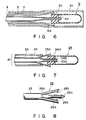
- the outer tube 2 has the same diameter over its entire length. As shown in Fig. 6, however, the distal portion 2a may be expanded to have such a large inner diameter that the portion 2a admits the unexpanded balloon 5 with the proximal portion 5a of the balloon 5 held by the chuck 6 formed on the intermediate tube 3. This structure is preferably used to hinder the balloon 5 from being damaged while the balloon 5 is being moved to the dwelling portion.
- a catheter 21 has a double-tube unit comprising an outer tube 22 and an inner tube 23 coaxial therewith.
- the distal portion 23a of the inner tube 23 is formed slightly thinner than its remaining part and is inserted in an central opening 24b formed in the center of the proximal portion 24a of a balloon 24 so as to communicate with its interior.
- a chuck 25 comprising three holding pieces 25a arranged equidistantly in the circumferential direction so as to surround the distal portion 23a of the inner tube 23.
- the holding portions 25a are normally opened most widely at their distal ends in such a manner that they can hold the outer peripheral surface of the proximal portion 24a of the balloon 24.
- each of the holding pieces 25a is formed with an inwardly projecting hook 25b.
- the hooks 25b bite in the outer peripheral surface of the proximal portion 24a of the balloon 24 to hold the same when the balloon 24 is connected to the catheter 21 as shown in Fig. 7.
- the distal portion of the outer tube 22, which surrounds the inner tube 23 at a spacing from its outer peripheral surface, has an inner diameter much smaller than the diameter of the distal end of the chuck 25 formed on the inner tube 23 when the chuck 25 is opened.
- the movement of the inner tube 23 into and out of the outer tube 22 causes the chuck 25 to be pushed inwardly by the outer tube 22 and released therefrom, respectively, whereby the chuck 25 freely closes or opens.
- This embodiment can be modified as shown in Fig. 10, in which the distal portion 22a may be expanded to have such a large diameter that the portion 22a admits the unexpanded balloon 24 with the proximal portion 24a of the balloon 24 held by the chuck 25 formed on the inner tube 22.
- This structure is preferably used to hinder the balloon 24 from being damaged while the balloon 24 is being moved to the dwelling portion.
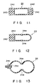
- the shape of the balloon is not limited to that of the balloon 24 of the second embodiment, but, as shown in Fig. 11, the distal portion 24c of the balloon 24 may be made solid, and a belt-type marker 24d made of X-ray opaque substance as described above may be fixed to or embedded in the outer peripheral surface of the portion 24c. Further, as shown in Fig. 12, the intermediate portion of the part, to be expanded, of the balloon 24 may be formed with a thick portion 24e so as to take a bottle-gourd shape when the balloon 24 is expanded as shown in Fig. 13. It is preferred that the opening 24b of the balloon 24 should be closed except when the inner tube is inserted in a blood vessel or the like such that the filler in the balloon is prevented from being discharged from the opening 24b.
- the balloon catheter assembly according to this invention has such a structure that the catheter comprises a double-tube unit or a triple-tube unit in which the inner tube or the outer tube of the structures is provided at the distal end thereof with a freely openable and closable chuck thereby to hold or release the balloon. Therefore, the catheter assembly according to this invention provides the following technical features: The balloon does not fall out during the operation of the catheter assembly and it becomes easy to collect the balloon again.
- the balloon when the balloon is expanded by accident, it can be contracted if the filler has not yet been gelled therein.
- the breakage of the balloon can be prevented by installing the balloon in the outer tube.
- the simple structure of the balloon enables the whole catheter assembly to be small-sized.
- the balloon catheter assembly according to this invention is useful to occlude a blood vessel such as a patient's artery during percutaneous surgery.
Landscapes
- Health & Medical Sciences (AREA)
- Surgery (AREA)
- Life Sciences & Earth Sciences (AREA)
- Heart & Thoracic Surgery (AREA)
- Nuclear Medicine, Radiotherapy & Molecular Imaging (AREA)
- Vascular Medicine (AREA)
- Engineering & Computer Science (AREA)
- Biomedical Technology (AREA)
- Reproductive Health (AREA)
- Medical Informatics (AREA)
- Molecular Biology (AREA)
- Animal Behavior & Ethology (AREA)
- General Health & Medical Sciences (AREA)
- Public Health (AREA)
- Veterinary Medicine (AREA)
- Media Introduction/Drainage Providing Device (AREA)
Abstract
Description
- This invention relates to a balloon catheter assembly comprising a detachable occluding balloon for occluding a path of a body fluid such as a blood vessel and a tube having a distal end portion removably inserted in an opening of the balloon, and to a guide sheath for guiding the introduction of the catheter.
- An occluding balloon is used for mainly occluding a blood vessel such as an artery when, for example, a percutaneous surgery of congenital cardiopathy due to patent duct arteriosus is carried out.
- The PCT Patent Announcement Sho 57-500720, for example, discloses a balloon catheter having an occluding balloon in which the balloon is separable at a required portion. However, this balloon catheter is encountered with the following problems:
- Since the balloon has a complicated structure, it cannot be rendered small.
- Further after the balloon has been expanded by accident, it cannot be contracted again.
- Still further, it is feared that since the balloon is fitted only to the distal portion of the catheter, it falls off by accident during its operation.
- A similar balloon catheter is disclosed in the Japanese unexamined patent application publication Sho 59-34269. Since the balloon is also only fitted to a cannula, it likely fall out by accident. If the connecting strength of the fitting portion is enhanced, the balloon can be prevented from falling off. However, it becomes difficult to separate the balloon from the catheter; the balloon gives an excess stress to the blood vessel to be occluded; and such a bulky structure of the balloon may cause the breakage thereof.
- The balloon can be threadably connected to the catheter by means of screw. When the balloon is to be separated from the distal portion of the catheter assembly, however, the torque is not easily transmitted to the connecting portion of the balloon with the result that this may cause such trouble that the balloon would not be easily separated from the catheter, and the balloon would be twisted to be broken as well.
- As a method of introducing an occluding balloon to a dwelling portion of blood vessel, such as a peripheral blood vessel e.g. a cerebral blood vessel, the balloon is slightly expanded in advance to be carried by a blood stream. However, this method is not suitable for sending an occluding balloon to a vascular portion where a blood flow is rather weak. This method is not applicable to the transmission of the balloon to the vicinity of a heart.
- The method of transmitting an occluding balloon in a blood vessel while exposing the balloon as disclosed in the PCT Patent Announcement Sho 57-500720, will not only lead to the breakage of the balloon but makes it difficult to easily and accurately transmit the balloon to the required dwelling portion.
- Another prior art balloon catheter assembly disclosing the features of the preamble of the independent claims is known from US-A-4,545,367. In this known catheter a distal end portion of a cannula is inserted into an opening of an expandable balloon. However, in this device no further means is provided in order to secure and additionally hold the balloon on the tip end of the cannula during handling of the catheter.
- This invention provides a balloon catheter assembly in which a balloon does not easily fall off during the transmitting operation thereby ensuring the introduction of the balloon to the required portion to be occluded, and, even if the balloon is expanded by accident, it can be contracted to the original size if a filler has not yet been gelled.
- This invention further provides a balloon catheter assembly in which an operator can easily observe how a balloon occludes the required portion.
- The invention still further provides a balloon catheter which is simple in structure and in which a balloon can be rendered small and can not be easily broken.
- According to an embodiment of this invention, a balloon catheter assembly is comprising an expandable balloon having an opening at a proximal portion thereof, an inner tube having a distal portion detachably fitted in the opening of the balloon, a chuck surrounding a distal portion of the inner tube and fixed to an outer peripheral surface the inner tube, the chuck having a plurality of holding pieces whose distal ends extend outwardly and radially, and an outer tube coaxially surrounding the inner tube leaving a space therebetween, wherein the holding portions are adapted to be pressed inwardly by a distal end of the outer tube to hold the proximal portion of the balloon when the inner tube is pulled into the outer tube, and the holding portions are automatically opened and expanded to release the proximal portion of the balloon when the chuck is pushed out of the distal end of the outer tube.
- With the catheter assembly having the fundamental structure as described above, a check valve may be provided at the proximal end of the outer tube such that the inner tube is extended out through the check valve thereby preventing a body fluid such as blood from flowing reversely when the distal portion of the catheter is inserted into a body.
- Further, an infusion port may be connected to the check valve provided at the outer tube, and another infusion port for a balloon expanding filler may be connected to the proximal end of the outer tube.
- Still further, the unexpanded balloon may be properly accommodated in the distal portion of the outer tube.
- According to another embodiment, a balloon catheter having a further fundamental structure is comprising an expandable balloon having an opening at a proximal portion thereof, an inner tube having a distal portion detachably inserted in the opening of the balloon, an intermediate tube coaxially surrounding the inner tube leaving a space therebetween and provided at a distal portion thereof with a chuck having a plurality of openable holding pieces, and an outer tube coaxially surrounding the intermediate tube leaving a space therebetween, wherein the chuck is pulled in the outer tube, and the chuck releases the proximal portion of the balloon when the chuck is pushed out of the distal end of the outer tube.
- With the catheter assembly having the second fundamental structure, the intermediate and outer tubes may have connectors connected to respective check valves provided at the proximal ends of the intermediate and outer tubes such that the intermediate tube is extended outwardly through the check valve of the outer tube and the inner tube is extended outwardly through the check valve of the intermediate tube thereby preventing a body fluid such as blood from flowing reversely.
- Further, infusion ports may be connected to the check valves at the inner and outer tubes, and another infusion port for a balloon expanding filler may be connected to the proximal end of the inner tube.
- Still further, the unexpanded balloon may be suitably installed in the distal end of the outer tube.
- More further, a circular thick portion is formed at the middle circular portion of the balloon such that the balloon takes a bottle-gourd shape when it is expanded.
- This invention further provides a balloon catheter assembly having any of the above structures and additionally a guide sheath which has a tube body having such an inner diameter that the guide sheath permits the balloon catheter to be guided and which guides the balloon to a required dwelling portion.
- It is preferred that a check valve be connected to the proximal end of the guide sheath and an infusion port in series.
- It is also preferred that the guide sheath is made of material mixed with X-ray opaque substance.
-
- Fig. 1 is an enlarged cross-sectional view of the distal portion of an occluding balloon catheter according to this invention;
- Fig. 2 is a perspective view of an intermediate tube of the catheter in Fig. 1;
- Fig. 3 is a cross-sectional view of the same embodiment as that in Fig. 1, with the balloon expanded;
- Fig. 4 is a plan view of an embodiment of the overall occluding balloon catheter assembly according to this invention;
- Fig. 5 is a plan view of an embodiment of the guide sheath;
- Figs. 6 and 7 are cross-sectional views of other embodiments of the occluding balloon catheter assembly according to this invention;
- Fig. 8 is a perspective view of the inner tube of the catheter in Fig. 7;
- Fig. 9 is a cross-sectional view of the same embodiment as that in Fig. 7, with the balloon expanded;
- Fig. 10 is a cross-sectional view of another embodiment of the occluding balloon catheter; and
- Figs. 11 to 13 are cross-sectional views of modifications of the balloon.
- This invention will be explained with reference to embodiments shown in the drawings.
- Fig. 1 shows the distal portion of the occluding balloon catheter according to this invention. As seen from this figure, a
main catheter 1 is formed with a triple-tube unit comprising anouter tube 2, anintermediate tube 3 and aninner tube 4 arranged coaxially with each other. Theinner tube 4 has a slightly thinner distal portion 4a and is inserted in an opening 5b formed in the center of theproximal portion 5a of aballoon 5 so as to communicate with the interior of theballoon 5. - The
intermediate tube 3 surrounding theinner tube 4 at a spacing is formed at its distal end with achuck portion 6 having a plurality of holdingportions 6a which selectively opens and closes. As shown in Fig. 2, theholding portions 6a forming thechuck portion 6 are four in number and are integral with theintermediate tube 3. They normally open most widely at their distal ends, and the inner diameter defined by their distal ends is much larger than the outer diameter of theproximal portion 5a of the balloon when they are opened. On the distal end of each of theholding portions 6a is formed ahook 6b projecting inwardly of thechuck 6. Thehooks 6b bite into the outer peripheral wall of theproximal portion 5a of theballoon 5 to hold the same, at the time of engagement as shown in Fig. 1. - The
outer tube 2 surrounding theintermediate pipe 3 at a spacing from the outer periphery of theouter tube 2 has at its distal end an inner diameter much smaller than the diameter defined by the distal end of thechuck 6 formed on theintermediate tube 3 when the chuck is expanded such that the movement of theintermediate tube 3 into and out of theouter tube 2 causes thechuck 6 to be pushed inwardly by theintermediate tube 3 and to be released therefrom, respectively, whereby thechuck 6 freely closes or opens. - When a filler is introduced into the
balloon 5 through theinner tube 4, theballoon 5 is expanded as shown in Fig. 3. The material of theballoon 5 may be mixed with X-ray opaque substance such as platinum, gold or the like which constitutes a marker. - The total structure of this occluding catheter assembly will be explained.
- As shown in Fig. 4, the proximal ends of the
intermediate tube 3 and theouter tube 2 are connected tocheck valves 8a and 8b, respectively, viaconnectors 7a and 7b. However, theconnectors 7a and 7b are not always necessary, but the proximal ends of theintermediate tube 3 and theouter tube 2 may be directly connected to therespective check valves 8a and 8b. Further, theintermediate tube 3 is led out from theouter tube 2 through thecheck valve 8b connected to theouter tube 2, and likewise theinner tube 4 is led out from theintermediate tube 3 through the check valve 8a connected to theintermediate tube 3, thereby preventing a body fluid such as blood from flowing reversely. - As shown in Fig. 4, the
check valves 8a and 8b are connected toinfusion ports 10a and 10b comprising two-way valves, three way valves or the like, respectively, via connectingtubes 9a and 9b. Physiological salt solution, for example, is infused continuously or intermittently in thetubes infusion ports 10a and 10b, so that blood or other body fluid which would otherwise enter theouter tube 2 and theintermediate tube 3 during the operation of the catheter, is excluded. This process is intended to prevent blood or the like entering the catheter from being coagulated so as to operate the catheter normally. - An infusion port 10c (preferably, a two-way valve or a three-way valve) is connected to the proximal end of the
inner tube 4 via a connector 7c so as to infuse a balloon expanding filler. - In general, the
inner tube 4, theintermediate tube 3 and theouter tube 2 are made of such thermoplastic resin as polyethylene, polyolefin, ethylene-vinylacetate copolymer, polyester, polyvinylchloride, polyurethane, fluoric resin and nylon. - The material of the
balloon 5 can be selected from elastic material such as silicone rubber, polyurethane and latex. A mesh made of nylon, polyethelene terephthalate, polyurethane or the like is embedded in the thick portion of theballoon 5 such that theballoon 5 is not expanded beyond a required size. - A guide sheath 11 comprises a tube body having an inner diameter permitting the
catheter 1 as well as theballoon 5 to be inserted into the sheath 11. As shown in Fig. 5, aconnector 12 accommodating a check valve is preferably connected to the proximal end of the guide sheath 11. Aninfusion port 13 for infusing physiological salt solution into the guide sheath 11 connected to theconnector 12 via atube 14. This arrangement hinders the reverse flow of blood or the like when the guide sheath 11 is inserted in the body and excludes the blood or the like which has entered the guide sheath 11 by means of physiological salt solution or the like. - Like the
catheter 1, the guide sheath 11 is generally made of thermoplastic resin such as polyolefin, ethylene-vinylacetate copolymer, polyester, polyvinylchloride, polyurethane, fluoric resin or nylon. - There will be explained the process how to dwell the balloon in a blood vessel by using the balloon catheter assembly.
- First, a guide wire (not shown) is moved to a balloon dwelling portion by the similar method of angiography. The guide wire may be further advanced beyond the dwelling portion. Secondly, the guide sheath 11 set with a dilator (not shown) is inserted into the blood vessel along the guide wire until it reaches the balloon dwelling portion. The dilator is required when the guide sheath 11 begins to be inserted into the blood vessel, but it may be removed when the guide sheath 11 is moved to the balloon dwelling portion. Thirdly, the guide wire is removed when the guide sheath 11 has been moved to the balloon dwelling portion.
- Thereafter, the
catheter 1 is introduced to the dwelling portion through the guide sheath 11 with theballoon 5 held at the distal end of thecatheter 1 as shown in Fig. 1. During the introduction of thecatheter 1, theballoon 5 does not fall off because itsdistal portion 5a is firmly held by thechuck 6 formed on the distal end of theintermediate tube 3. - After the
balloon 5 has been positioned in the dwelling portion as described above, the balloon expanding filler is introduced in theballoon 5 through the infusion port 10c at the proximal end of theinner tube 4 to expand theballoon 5 to a required size as shown in Fig. 3. The filler is made of gelable liquid such as silicone RTV (Silicone Rubber KE12 RTV - a trade name of Shin-etsu Kagaku Kogyo Kabushiki Kaisha), cross-linked type modified polyvinyl alcohol or the like (with which X-ray opaque substance such as tungsten, bismuth oxide, barium sulfate or the like may be mixed). When the filler is mixed with the X-ray opaque substance, the catheter assembly can be used in X-ray fluoroscopy. - After the filler has been cured in the
balloon 5, theouter tube 2 is retracted towards the proximal ends of theintermediate tube 3 and theinner tube 4, whereby thechuck 6 opens automatically and is disengaged from theproximal portion 5a of theballoon 5. Then, the distal end of theinner tube 4 is released from theproximal portion 5a of theballoon 5 by pulling theinner tube 4 towards its proximal end with theballoon 5 left in the required dwelling portion. If necessary, physiological salt solution is continuously or intermittently infused into the catheter through theinfusion ports 10a and 10b. - In the above embodiment, the
outer tube 2 has the same diameter over its entire length. As shown in Fig. 6, however, the distal portion 2a may be expanded to have such a large inner diameter that the portion 2a admits theunexpanded balloon 5 with theproximal portion 5a of theballoon 5 held by thechuck 6 formed on theintermediate tube 3. This structure is preferably used to hinder theballoon 5 from being damaged while theballoon 5 is being moved to the dwelling portion. - In Fig. 7 is shown another embodiment of the distal portion of the occluding balloon catheter according to this invention. As clearly understood from this figure, a
catheter 21 has a double-tube unit comprising anouter tube 22 and aninner tube 23 coaxial therewith. Thedistal portion 23a of theinner tube 23 is formed slightly thinner than its remaining part and is inserted in ancentral opening 24b formed in the center of theproximal portion 24a of aballoon 24 so as to communicate with its interior. - On the distal end of the
inner tube 23 is formed achuck 25 comprising three holdingpieces 25a arranged equidistantly in the circumferential direction so as to surround thedistal portion 23a of theinner tube 23. As shown in Fig. 8, the holdingportions 25a are normally opened most widely at their distal ends in such a manner that they can hold the outer peripheral surface of theproximal portion 24a of theballoon 24. - The distal end of each of the holding
pieces 25a is formed with an inwardly projectinghook 25b. Thehooks 25b bite in the outer peripheral surface of theproximal portion 24a of theballoon 24 to hold the same when theballoon 24 is connected to thecatheter 21 as shown in Fig. 7. - The distal portion of the
outer tube 22, which surrounds theinner tube 23 at a spacing from its outer peripheral surface, has an inner diameter much smaller than the diameter of the distal end of thechuck 25 formed on theinner tube 23 when thechuck 25 is opened. The movement of theinner tube 23 into and out of theouter tube 22 causes thechuck 25 to be pushed inwardly by theouter tube 22 and released therefrom, respectively, whereby thechuck 25 freely closes or opens. - The structure, functions and usage of this embodiment other than those as described above are the same as those of the embodiment shown in Fig. 1. As shown in Fig. 9, after the
balloon 24 has been expanded to a required size, theouter tube 22 is moved towards the proximal end of theinner tube 23 to open thechuck 25a, and then theinner tube 23 is also pulled towards it proximal end, whereby thedistal portion 23a of theinner tube 23 is released from theproximal portion 24 of theballoon 24 with only theballoon 24 left in the required dwelling portion. - This embodiment can be modified as shown in Fig. 10, in which the distal portion 22a may be expanded to have such a large diameter that the portion 22a admits the
unexpanded balloon 24 with theproximal portion 24a of theballoon 24 held by thechuck 25 formed on theinner tube 22. This structure is preferably used to hinder theballoon 24 from being damaged while theballoon 24 is being moved to the dwelling portion. - The shape of the balloon is not limited to that of the
balloon 24 of the second embodiment, but, as shown in Fig. 11, the distal portion 24c of theballoon 24 may be made solid, and a belt-type marker 24d made of X-ray opaque substance as described above may be fixed to or embedded in the outer peripheral surface of the portion 24c. Further, as shown in Fig. 12, the intermediate portion of the part, to be expanded, of theballoon 24 may be formed with athick portion 24e so as to take a bottle-gourd shape when theballoon 24 is expanded as shown in Fig. 13. It is preferred that theopening 24b of theballoon 24 should be closed except when the inner tube is inserted in a blood vessel or the like such that the filler in the balloon is prevented from being discharged from theopening 24b. - The balloon catheter assembly according to this invention has such a structure that the catheter comprises a double-tube unit or a triple-tube unit in which the inner tube or the outer tube of the structures is provided at the distal end thereof with a freely openable and closable chuck thereby to hold or release the balloon. Therefore, the catheter assembly according to this invention provides the following technical features:
The balloon does not fall out during the operation of the catheter assembly and it becomes easy to collect the balloon again. - Further, when the balloon is expanded by accident, it can be contracted if the filler has not yet been gelled therein.
- Still further, the breakage of the balloon can be prevented by installing the balloon in the outer tube.
- In addition, the simple structure of the balloon enables the whole catheter assembly to be small-sized.
- The balloon catheter assembly according to this invention is useful to occlude a blood vessel such as a patient's artery during percutaneous surgery.
Claims (20)
- A balloon catheter assembly with an expandable balloon (5, 24) having an opening (5b, 24b) in a proximal end portion (5a, 24a) thereof; an inner tube (4) having a distal portion (4a) removably inserted in said opening (5b, 24b) of said balloon (5, 24);
characterized by
an intermediate tube (3) coaxially surrounding said inner tube (4), leaving a space therebetween and provided at a distal end thereof with a chuck (6) comprising a plurality of expandable and contractible holding portions (6a);
and an outer tube (2) surrounding said intermediate tube (3), leaving a space therebetween;
said chuck (6) being adapted to be closed when pulled in said outer tube (2) and pressed by said distal end of said outer tube (2) thereby to hold said proximal portion (5a, 24a) of said balloon (5, 24), and adapted to be opened when pushed out of said distal end of said outer tube (2), thereby to release said proximal portion (5a, 24a) of said balloon (5, 24). - The balloon catheter assembly according to claim 1, characterized in that said intermediate tube (3) and said outer tube (2) have proximal ends connected to respective check valves (8a, 8b), said intermediate tube (3) extends outward from said outer tube (2) via said check valve (8b) connected to said outer tube (2), and said inner tube (4) extends outward from said intermediate tube (3) via said check valve (8a) connected to said intermediate tube (3), such that body fluid such as blood is prevented from flowing reversely when said distal portion of said catheter is inserted in a body.
- The balloon catheter assembly according to claim 2, characterized in that there are further provided infusion ports (10a, 10b) connected to said check valves (8a, 8b) connected to said intermediate tube (3) and said outer tube (2), respectively.
- The balloon catheter assembly according to claim 1, characterized in that said inner tube (4) has a proximal end connected to a balloon expanding infusion port (10c).
- The balloon catheter assembly according to claim 1, characterized in that said inner tube (4), said intermediate tube (3) and said outer tube (2) are molded from a resin selected from the group consisting of polyethylene, polypropylene, ethylene-vinylacetate copolymer, polyester, polyvinylchloride, polyurethane, fluoric resin and polyamide.
- A balloon catheter assembly with an expandable balloon (24) having an opening (24b) formed in a proximal end portion (24a), said proximal end portion (24a) having an outer peripheral surface;
an inner tube (23) having a distal portion (23a) removably inserted in said opening (24b) of said balloon (24);
characterized by
a chuck (25) formed on or fixed to said distal portion (23a) of said inner tube (23), surrounding said distal portion (23a) of said inner tube (23), and having a plurality of holding portions (25a) radially outwardly extending at distal ends thereof; and
an outer tube (22) coaxially surrounding said inner tube (23), leaving a space therebetween and having a distal end, said chuck (25) being adapted to be closed when said inner tube (23) is pulled in said outer tube (22) by pushing said holding portions (25a) inwardly by said distal end of said outer tube (22) to hold said proximal portion (24a) of said balloon (24) on said outer peripheral surface thereof, and adapted to release said proximal portion (24a) of said balloon (24) when projected from said distal end of said outer tube (22) to be disengaged therefrom. - The balloon catheter assembly according to claim 6, characterized in that said outer tube (22) has a proximal end connected to a check valve, and said inner tube (23) extends outward from said outer tube (22) through said check valve (25), such that body fluid such as blood is prevented from flowing reversely when said distal portion of said catheter is inserted in a body.
- The balloon catheter assembly according to claim 6, characterized in that there is further provided an infusion port (10b) connected to said outer tube (22).
- The balloon catheter assembly according to claim 6, characterized in that said inner tube (23) has a proximal end connected to an infusion port (10c) for injecting into said balloon (24) a filler for expanding said balloon (24).
- The balloon catheter assembly according to claim 6, characterized in that said inner tube (23) and said outer tube (22) are molded from a resin selected from the group consisting of polyethylene, polypropylene, ethylene-vinylacetate copolymer, polyester, polyvinylchloride, fluoric resin and polyamide.
- The balloon catheter assembly according to claim 1 or claim 6, characterized in that there is further provided a balloon expanding filler made of material which assumes a liquid state when said filler is infused into said balloon (5, 24) and a gelled state at a predetermined time after said filler has been infused into said balloon (5, 24).
- The balloon catheter assembly according to claim 11, characterized in that said filler is mixed with X-ray opaque substance.
- The balloon catheter assembly according to claim 1 or claim 6, characterized in that said balloon (5, 24) is molded from at least one material selected from the group consisting of silicone rubber, polyurethane and latex.
- The balloon catheter assembly according to claim 1 or claim 6, characterized in that said balloon (24) has a circular middle portion (24e) which is thick such that said balloon (24) takes a bottle-gourd shape when expanded.
- The balloon catheter assembly according to claim 14, characterized in that said circular middle portion (24e) of said balloon (24) includes a mesh molded from at least one material selected from the group consisting of nylon, polyethylene terephthalate and polyurethane.
- The balloon catheter assembly according to claim 13, characterized in that said balloon (24) has a marker (24d) made of X-ray opaque substance.
- A balloon catheter assembly according to one or more of the preceding claims 1 to 16, characterized by further comprising:
a guide sheath (11) comprising a tube body having an inner diameter large enough to permit said outer tube (2, 22) to be moved within said tube body and to permit said balloon (5, 24) to be introduced into a predetermined dwelling portion. - The balloon catheter assembly according to claim 17, characterized in that said guide sheath (11) has a proximal end connected to a check valve (12).
- The balloon catheter assembly according to claim 18, characterized in that there is further provided an infusion port (13) connected to said check valve (12).
- The balloon catheter assembly according to claim 17, characterized in that said guide sheath (11) is made of material mixed with X-ray opaque substance.
Applications Claiming Priority (7)
| Application Number | Priority Date | Filing Date | Title |
|---|---|---|---|
| JP61284606A JPS63139565A (en) | 1986-11-29 | 1986-11-29 | Balloon catheter apparatus |
| JP284607/86 | 1986-11-29 | ||
| JP284608/86 | 1986-11-29 | ||
| JP61284608A JPS63139567A (en) | 1986-11-29 | 1986-11-29 | Balloon catheter |
| JP284606/86 | 1986-11-29 | ||
| JP61284607A JPS63139566A (en) | 1986-11-29 | 1986-11-29 | Balloon catheter |
| PCT/JP1987/000922 WO1988003817A1 (en) | 1986-11-29 | 1987-11-27 | Catheter equipped with balloon |
Publications (3)
| Publication Number | Publication Date |
|---|---|
| EP0375775A4 EP0375775A4 (en) | 1990-04-10 |
| EP0375775A1 EP0375775A1 (en) | 1990-07-04 |
| EP0375775B1 true EP0375775B1 (en) | 1994-08-31 |
Family
ID=27337105
Family Applications (1)
| Application Number | Title | Priority Date | Filing Date |
|---|---|---|---|
| EP87907823A Expired - Lifetime EP0375775B1 (en) | 1986-11-29 | 1987-11-27 | Catheter equipped with balloon |
Country Status (5)
| Country | Link |
|---|---|
| US (1) | US5002556A (en) |
| EP (1) | EP0375775B1 (en) |
| AU (1) | AU613886B2 (en) |
| DE (1) | DE3750480T2 (en) |
| WO (1) | WO1988003817A1 (en) |
Cited By (5)
| Publication number | Priority date | Publication date | Assignee | Title |
|---|---|---|---|---|
| US7976527B2 (en) | 1997-10-17 | 2011-07-12 | Micro Therapeutics, Inc. | Device and method for controlling injection of liquid embolic composition |
| USRE42625E1 (en) | 1990-03-13 | 2011-08-16 | The Regents Of The University Of California | Endovascular electrolytically detachable wire and tip for the formation of thrombus in arteries, veins, aneurysms, vascular malformations and arteriovenous fistulas |
| USRE42662E1 (en) | 1990-03-13 | 2011-08-30 | The Regents Of The University Of California | Endovascular electrolytically detachable wire and tip for the formation of thrombus in arteries, veins, aneurysms, vascular malformations and arteriovenous fistulas |
| USRE42756E1 (en) | 1990-03-13 | 2011-09-27 | The Regents Of The University Of California | Endovascular electrolytically detachable wire and tip for the formation of thrombus in arteries, veins, aneurysms, vascular malformations and arteriovenous fistulas |
| US9468739B2 (en) | 2008-08-19 | 2016-10-18 | Covidien Lp | Detachable tip microcatheter |
Families Citing this family (222)
| Publication number | Priority date | Publication date | Assignee | Title |
|---|---|---|---|---|
| EP0347458B1 (en) * | 1987-01-13 | 1994-03-30 | Terumo Kabushiki Kaisha | Balloon catheter and production thereof |
| US5044369A (en) * | 1989-01-23 | 1991-09-03 | Harvinder Sahota | Bent topless catheters |
| EP0420488B1 (en) | 1989-09-25 | 1993-07-21 | Schneider (Usa) Inc. | Multilayer extrusion as process for making angioplasty balloons |
| US5843017A (en) * | 1990-07-24 | 1998-12-01 | Yoon; Inbae | Multifunctional tissue dissecting instrument |
| US5379759A (en) * | 1991-02-04 | 1995-01-10 | Sewell, Jr.; Frank K. | Retractor for endoscopic surgery |
| US5359995A (en) * | 1991-02-04 | 1994-11-01 | Sewell Jr Frank | Method of using an inflatable laparoscopic retractor |
| US5188630A (en) * | 1991-03-25 | 1993-02-23 | Christoudias George C | Christoudias endospongestick probe |
| US5195969A (en) * | 1991-04-26 | 1993-03-23 | Boston Scientific Corporation | Co-extruded medical balloons and catheter using such balloons |
| US5217484A (en) * | 1991-06-07 | 1993-06-08 | Marks Michael P | Retractable-wire catheter device and method |
| FR2677873B1 (en) * | 1991-06-20 | 1997-12-26 | Celsa Lg | IMPROVED INTRODUCER FOR CELLAR VEIN FILTER. |
| US5222970A (en) * | 1991-09-06 | 1993-06-29 | William A. Cook Australia Pty. Ltd. | Method of and system for mounting a vascular occlusion balloon on a delivery catheter |
| ES2109969T3 (en) * | 1991-10-11 | 1998-02-01 | Angiomed Ag | PROCEDURE FOR THE DILATION OF A STENOSIS. |
| US5290310A (en) * | 1991-10-30 | 1994-03-01 | Howmedica, Inc. | Hemostatic implant introducer |
| USRE37117E1 (en) | 1992-09-22 | 2001-03-27 | Target Therapeutics, Inc. | Detachable embolic coil assembly using interlocking clasps and method of use |
| US5925059A (en) * | 1993-04-19 | 1999-07-20 | Target Therapeutics, Inc. | Detachable embolic coil assembly |
| US5800453A (en) * | 1993-04-19 | 1998-09-01 | Target Therapeutics, Inc. | Detachable embolic coil assembly using interlocking hooks and slots |
| US5370617A (en) * | 1993-09-17 | 1994-12-06 | Sahota; Harvinder | Blood perfusion balloon catheter |
| JP3577082B2 (en) | 1993-10-01 | 2004-10-13 | ボストン・サイエンティフィック・コーポレーション | Medical device balloon made of thermoplastic elastomer |
| US6896842B1 (en) * | 1993-10-01 | 2005-05-24 | Boston Scientific Corporation | Medical device balloons containing thermoplastic elastomers |
| US5411016A (en) * | 1994-02-22 | 1995-05-02 | Scimed Life Systems, Inc. | Intravascular balloon catheter for use in combination with an angioscope |
| US5499995C1 (en) * | 1994-05-25 | 2002-03-12 | Paul S Teirstein | Body passageway closure apparatus and method of use |
| US5578009A (en) * | 1994-07-20 | 1996-11-26 | Danforth Biomedical Incorporated | Catheter system with push rod for advancement of balloon along guidewire |
| EP0794811B1 (en) * | 1994-11-23 | 2002-07-31 | Micro Interventional Systems, Inc. | High torque balloon catheter |
| US5814062A (en) * | 1994-12-22 | 1998-09-29 | Target Therapeutics, Inc. | Implant delivery assembly with expandable coupling/decoupling mechanism |
| US6027518A (en) * | 1995-05-30 | 2000-02-22 | Gaber; Benny | Seizing instrument |
| IL113922A (en) * | 1995-05-30 | 1999-03-12 | Gaber Benny | Seizing instrument |
| FR2735967B1 (en) * | 1995-06-27 | 1998-03-06 | Perouse Implant Lab | VASCULAR SURGERY TOOL AND ITS USE |
| US6027460A (en) * | 1995-09-14 | 2000-02-22 | Shturman Cardiology Systems, Inc. | Rotatable intravascular apparatus |
| US5833658A (en) * | 1996-04-29 | 1998-11-10 | Levy; Robert J. | Catheters for the delivery of solutions and suspensions |
| US6186978B1 (en) | 1996-08-07 | 2001-02-13 | Target Therapeutics, Inc. | Braid reinforced infusion catheter with inflatable membrane |
| NO973633L (en) * | 1996-08-07 | 1998-02-09 | Target Therapeutics Inc | Seal-enhanced infusion catheter with inflatable membrane |
| US5951514A (en) * | 1997-03-07 | 1999-09-14 | Sahota; Harvinder | Multi-lobe perfusion balloon |
| US5800393A (en) * | 1997-03-07 | 1998-09-01 | Sahota; Harvinder | Wire perfusion catheter |
| US6146373A (en) | 1997-10-17 | 2000-11-14 | Micro Therapeutics, Inc. | Catheter system and method for injection of a liquid embolic composition and a solidification agent |
| JPH11244386A (en) * | 1998-01-01 | 1999-09-14 | Ge Yokogawa Medical Systems Ltd | Method for stopping blood circulation and heater |
| US6293960B1 (en) * | 1998-05-22 | 2001-09-25 | Micrus Corporation | Catheter with shape memory polymer distal tip for deployment of therapeutic devices |
| AU4073099A (en) * | 1998-07-21 | 2000-02-14 | Heartport, Inc. | Multi-lumen catheters and methods of use and manufacture |
| US6500149B2 (en) | 1998-08-31 | 2002-12-31 | Deepak Gandhi | Apparatus for deployment of micro-coil using a catheter |
| US6478773B1 (en) * | 1998-12-21 | 2002-11-12 | Micrus Corporation | Apparatus for deployment of micro-coil using a catheter |
| US6296622B1 (en) | 1998-12-21 | 2001-10-02 | Micrus Corporation | Endoluminal device delivery system using axially recovering shape memory material |
| US6102932A (en) * | 1998-12-15 | 2000-08-15 | Micrus Corporation | Intravascular device push wire delivery system |
| US6835185B2 (en) * | 1998-12-21 | 2004-12-28 | Micrus Corporation | Intravascular device deployment mechanism incorporating mechanical detachment |
| US6165140A (en) * | 1998-12-28 | 2000-12-26 | Micrus Corporation | Composite guidewire |
| US6352531B1 (en) | 1999-03-24 | 2002-03-05 | Micrus Corporation | Variable stiffness optical fiber shaft |
| US6887235B2 (en) * | 1999-03-24 | 2005-05-03 | Micrus Corporation | Variable stiffness heating catheter |
| US7740637B2 (en) * | 2000-02-09 | 2010-06-22 | Micrus Endovascular Corporation | Apparatus and method for deployment of a therapeutic device using a catheter |
| US6964667B2 (en) * | 2000-06-23 | 2005-11-15 | Sdgi Holdings, Inc. | Formed in place fixation system with thermal acceleration |
| CA2692387C (en) * | 2000-06-23 | 2011-02-22 | University Of Southern California | Percutaneous vertebral fusion system |
| US6899713B2 (en) | 2000-06-23 | 2005-05-31 | Vertelink Corporation | Formable orthopedic fixation system |
| US6875212B2 (en) * | 2000-06-23 | 2005-04-05 | Vertelink Corporation | Curable media for implantable medical device |
| CA2419811A1 (en) | 2000-08-18 | 2002-02-28 | Atritech, Inc. | Expandable implant devices for filtering blood flow from atrial appendages |
| US6663646B1 (en) * | 2000-10-24 | 2003-12-16 | Tilak M. Shah | Isotropically expansible balloon articles useful in in vivo lumenal procedures, and method of making such balloon articles |
| DE20103653U1 (en) * | 2001-03-02 | 2001-05-17 | B. Braun Melsungen Ag, 34212 Melsungen | Ureter drainage device |
| US6837901B2 (en) * | 2001-04-27 | 2005-01-04 | Intek Technology L.L.C. | Methods for delivering, repositioning and/or retrieving self-expanding stents |
| US7160325B2 (en) * | 2001-05-15 | 2007-01-09 | Ams Research Corporation | Implantable medical balloon and valve |
| US7338511B2 (en) * | 2002-05-24 | 2008-03-04 | Boston Scientific-Scimed, Inc. | Solid embolic material with variable expansion |
| US20040059403A1 (en) * | 2002-09-24 | 2004-03-25 | Geriche, Inc. | Suture sleeve |
| US7455660B2 (en) * | 2002-12-18 | 2008-11-25 | Medical Components, Inc. | Locking guidewire straightener |
| US20050043585A1 (en) * | 2003-01-03 | 2005-02-24 | Arindam Datta | Reticulated elastomeric matrices, their manufacture and use in implantable devices |
| JP2007521843A (en) | 2003-05-15 | 2007-08-09 | バイオメリクス コーポレーション | Reticulated elastomeric matrix, its manufacture and use in implantable devices |
| US7632291B2 (en) * | 2003-06-13 | 2009-12-15 | Trivascular2, Inc. | Inflatable implant |
| US8343213B2 (en) | 2003-12-23 | 2013-01-01 | Sadra Medical, Inc. | Leaflet engagement elements and methods for use thereof |
| US7445631B2 (en) | 2003-12-23 | 2008-11-04 | Sadra Medical, Inc. | Methods and apparatus for endovascularly replacing a patient's heart valve |
| US8603160B2 (en) | 2003-12-23 | 2013-12-10 | Sadra Medical, Inc. | Method of using a retrievable heart valve anchor with a sheath |
| US8828078B2 (en) | 2003-12-23 | 2014-09-09 | Sadra Medical, Inc. | Methods and apparatus for endovascular heart valve replacement comprising tissue grasping elements |
| US9005273B2 (en) | 2003-12-23 | 2015-04-14 | Sadra Medical, Inc. | Assessing the location and performance of replacement heart valves |
| US8840663B2 (en) | 2003-12-23 | 2014-09-23 | Sadra Medical, Inc. | Repositionable heart valve method |
| US20050137694A1 (en) | 2003-12-23 | 2005-06-23 | Haug Ulrich R. | Methods and apparatus for endovascularly replacing a patient's heart valve |
| US8287584B2 (en) * | 2005-11-14 | 2012-10-16 | Sadra Medical, Inc. | Medical implant deployment tool |
| US7329279B2 (en) * | 2003-12-23 | 2008-02-12 | Sadra Medical, Inc. | Methods and apparatus for endovascularly replacing a patient's heart valve |
| EP1702247B8 (en) | 2003-12-23 | 2015-09-09 | Boston Scientific Scimed, Inc. | Repositionable heart valve |
| US7780725B2 (en) | 2004-06-16 | 2010-08-24 | Sadra Medical, Inc. | Everting heart valve |
| US8328868B2 (en) | 2004-11-05 | 2012-12-11 | Sadra Medical, Inc. | Medical devices and delivery systems for delivering medical devices |
| US7824442B2 (en) * | 2003-12-23 | 2010-11-02 | Sadra Medical, Inc. | Methods and apparatus for endovascularly replacing a heart valve |
| US9526609B2 (en) | 2003-12-23 | 2016-12-27 | Boston Scientific Scimed, Inc. | Methods and apparatus for endovascularly replacing a patient's heart valve |
| US7824443B2 (en) * | 2003-12-23 | 2010-11-02 | Sadra Medical, Inc. | Medical implant delivery and deployment tool |
| US7381219B2 (en) | 2003-12-23 | 2008-06-03 | Sadra Medical, Inc. | Low profile heart valve and delivery system |
| US20120041550A1 (en) | 2003-12-23 | 2012-02-16 | Sadra Medical, Inc. | Methods and Apparatus for Endovascular Heart Valve Replacement Comprising Tissue Grasping Elements |
| US20050137687A1 (en) | 2003-12-23 | 2005-06-23 | Sadra Medical | Heart valve anchor and method |
| US11278398B2 (en) | 2003-12-23 | 2022-03-22 | Boston Scientific Scimed, Inc. | Methods and apparatus for endovascular heart valve replacement comprising tissue grasping elements |
| US8579962B2 (en) * | 2003-12-23 | 2013-11-12 | Sadra Medical, Inc. | Methods and apparatus for performing valvuloplasty |
| US7959666B2 (en) * | 2003-12-23 | 2011-06-14 | Sadra Medical, Inc. | Methods and apparatus for endovascularly replacing a heart valve |
| US8182528B2 (en) | 2003-12-23 | 2012-05-22 | Sadra Medical, Inc. | Locking heart valve anchor |
| US7763077B2 (en) | 2003-12-24 | 2010-07-27 | Biomerix Corporation | Repair of spinal annular defects and annulo-nucleoplasty regeneration |
| US20070190108A1 (en) * | 2004-05-17 | 2007-08-16 | Arindam Datta | High performance reticulated elastomeric matrix preparation, properties, reinforcement, and use in surgical devices, tissue augmentation and/or tissue repair |
| DE502004008712D1 (en) | 2004-09-22 | 2009-01-29 | Dendron Gmbh | MEDICAL IMPLANT |
| ATE448737T1 (en) | 2004-09-22 | 2009-12-15 | Dendron Gmbh | DEVICE FOR IMPLANTING MICROWL COILS |
| US20090131866A1 (en) | 2004-11-12 | 2009-05-21 | Regents Of The University Of Minnesota | Veinous Occlusion Device and Methods of Using |
| US20060116714A1 (en) * | 2004-11-26 | 2006-06-01 | Ivan Sepetka | Coupling and release devices and methods for their assembly and use |
| WO2014082044A1 (en) | 2012-11-26 | 2014-05-30 | Spatz Fgia, Inc. | System and methods for internalization of components of an adjustable intragastric balloon |
| US7989157B2 (en) * | 2005-01-11 | 2011-08-02 | Medtronic, Inc. | Solution for storing bioprosthetic tissue used in a biological prosthesis |
| DE102005003632A1 (en) | 2005-01-20 | 2006-08-17 | Fraunhofer-Gesellschaft zur Förderung der angewandten Forschung e.V. | Catheter for the transvascular implantation of heart valve prostheses |
| US7962208B2 (en) | 2005-04-25 | 2011-06-14 | Cardiac Pacemakers, Inc. | Method and apparatus for pacing during revascularization |
| US7357809B2 (en) * | 2005-06-30 | 2008-04-15 | Cordis Neurovascular, Inc. | Chemically based vascular occlusion device deployment with gripping feature |
| US7712606B2 (en) | 2005-09-13 | 2010-05-11 | Sadra Medical, Inc. | Two-part package for medical implant |
| EP1945134A2 (en) * | 2005-11-10 | 2008-07-23 | Sentinel Group, LLC | Intragastric and transgastric device and method of visualization and therapeutic intervention |
| US20070213813A1 (en) | 2005-12-22 | 2007-09-13 | Symetis Sa | Stent-valves for valve replacement and associated methods and systems for surgery |
| EP1988851A2 (en) | 2006-02-14 | 2008-11-12 | Sadra Medical, Inc. | Systems and methods for delivering a medical implant |
| US7553321B2 (en) * | 2006-03-31 | 2009-06-30 | Cordis Development Corporation | Chemically based vascular occlusion device deployment |
| JP5230602B2 (en) | 2006-04-17 | 2013-07-10 | タイコ ヘルスケア グループ リミテッド パートナーシップ | System and method for mechanically positioning an endovascular implant |
| US8777979B2 (en) | 2006-04-17 | 2014-07-15 | Covidien Lp | System and method for mechanically positioning intravascular implants |
| KR20090010090A (en) * | 2006-05-11 | 2009-01-28 | 코럼나 피티와이 리미티드 | Implanting a tissue prosthesis |
| US8372114B2 (en) * | 2006-11-13 | 2013-02-12 | Electroformed Stents, Inc. | Over-the-wire exclusion device and system for delivery |
| US20080281350A1 (en) * | 2006-12-13 | 2008-11-13 | Biomerix Corporation | Aneurysm Occlusion Devices |
| US8758407B2 (en) * | 2006-12-21 | 2014-06-24 | Warsaw Orthopedic, Inc. | Methods for positioning a load-bearing orthopedic implant device in vivo |
| US7771476B2 (en) | 2006-12-21 | 2010-08-10 | Warsaw Orthopedic Inc. | Curable orthopedic implant devices configured to harden after placement in vivo by application of a cure-initiating energy before insertion |
| US8663328B2 (en) * | 2006-12-21 | 2014-03-04 | Warsaw Orthopedic, Inc. | Methods for positioning a load-bearing component of an orthopedic implant device by inserting a malleable device that hardens in vivo |
| US8480718B2 (en) * | 2006-12-21 | 2013-07-09 | Warsaw Orthopedic, Inc. | Curable orthopedic implant devices configured to be hardened after placement in vivo |
| KR20100015520A (en) | 2007-03-13 | 2010-02-12 | 마이크로 테라퓨틱스 인코포레이티드 | An implant including a coil and a stretch-resistant member |
| KR20100015521A (en) | 2007-03-13 | 2010-02-12 | 마이크로 테라퓨틱스 인코포레이티드 | An implant, a mandrel, and a method of forming an implant |
| ES2593085T3 (en) | 2007-03-15 | 2016-12-05 | Ortho-Space Ltd. | Prosthetic devices |
| US7896915B2 (en) | 2007-04-13 | 2011-03-01 | Jenavalve Technology, Inc. | Medical device for treating a heart valve insufficiency |
| US20090275971A1 (en) * | 2007-10-30 | 2009-11-05 | Boston Scientific Scimed, Inc. | Energy activated preloaded detachment mechanisms for implantable devices |
| ES2903231T3 (en) | 2008-02-26 | 2022-03-31 | Jenavalve Tech Inc | Stent for positioning and anchoring a valve prosthesis at an implantation site in a patient's heart |
| US9044318B2 (en) | 2008-02-26 | 2015-06-02 | Jenavalve Technology Gmbh | Stent for the positioning and anchoring of a valvular prosthesis |
| WO2010028310A2 (en) * | 2008-09-05 | 2010-03-11 | Cardiopolymers, Inc | Apparatus and method for capsule formation in tissue |
| JP5752137B2 (en) | 2009-10-15 | 2015-07-22 | インベンティオ エルエルシーInventio Llc | Disposable and reusable complex shape transparent endscope |
| US8440090B2 (en) | 2010-04-29 | 2013-05-14 | Abbott Cardiovascular Systems Inc. | Apparatus and method of making a variable stiffness multilayer catheter tubing |
| BR112012029896A2 (en) | 2010-05-25 | 2017-06-20 | Jenavalve Tech Inc | prosthetic heart valve for stent graft and stent graft |
| AU2011300644B2 (en) | 2010-09-10 | 2015-08-20 | Symetis Sa | Valve replacement devices and a system comprising the valve replacement device and a delivery device therefor |
| WO2012127309A1 (en) | 2011-03-21 | 2012-09-27 | Ontorfano Matteo | Disk-based valve apparatus and method for the treatment of valve dysfunction |
| CN103533983A (en) * | 2011-03-30 | 2014-01-22 | 康奈尔大学 | Intra-luminal access apparatus and methods of using the same |
| US9833126B2 (en) | 2011-04-05 | 2017-12-05 | Visualization Balloons, Llc | Balloon access device with features for engaging an endoscope |
| WO2012138815A1 (en) * | 2011-04-05 | 2012-10-11 | United States Endoscopy Group, Inc. | Balloon access device for endoscope |
| EP2520251A1 (en) | 2011-05-05 | 2012-11-07 | Symetis SA | Method and Apparatus for Compressing Stent-Valves |
| EP2731550B1 (en) | 2011-07-12 | 2016-02-24 | Boston Scientific Scimed, Inc. | Coupling system for a replacement valve |
| US10010437B2 (en) | 2011-10-17 | 2018-07-03 | W. L. Gore & Associates, Inc. | Endoluminal device retrieval devices and related systems and methods |
| US9289307B2 (en) | 2011-10-18 | 2016-03-22 | Ortho-Space Ltd. | Prosthetic devices and methods for using same |
| US9131926B2 (en) | 2011-11-10 | 2015-09-15 | Boston Scientific Scimed, Inc. | Direct connect flush system |
| US8940014B2 (en) | 2011-11-15 | 2015-01-27 | Boston Scientific Scimed, Inc. | Bond between components of a medical device |
| US9579104B2 (en) | 2011-11-30 | 2017-02-28 | Covidien Lp | Positioning and detaching implants |
| US8951243B2 (en) | 2011-12-03 | 2015-02-10 | Boston Scientific Scimed, Inc. | Medical device handle |
| US9277993B2 (en) | 2011-12-20 | 2016-03-08 | Boston Scientific Scimed, Inc. | Medical device delivery systems |
| US9510945B2 (en) | 2011-12-20 | 2016-12-06 | Boston Scientific Scimed Inc. | Medical device handle |
| US9011480B2 (en) | 2012-01-20 | 2015-04-21 | Covidien Lp | Aneurysm treatment coils |
| US10172708B2 (en) | 2012-01-25 | 2019-01-08 | Boston Scientific Scimed, Inc. | Valve assembly with a bioabsorbable gasket and a replaceable valve implant |
| US8882798B2 (en) * | 2012-02-13 | 2014-11-11 | Apollo Endosurgery, Inc. | Endoscopic tools for the removal of balloon-like intragastric devices |
| US9687245B2 (en) | 2012-03-23 | 2017-06-27 | Covidien Lp | Occlusive devices and methods of use |
| US9084857B2 (en) * | 2012-04-16 | 2015-07-21 | W. L. Gore & Associates, Inc. | Single access flow-reversal catheter devices and methods |
| US10124087B2 (en) | 2012-06-19 | 2018-11-13 | Covidien Lp | Detachable coupling for catheter |
| US9883941B2 (en) | 2012-06-19 | 2018-02-06 | Boston Scientific Scimed, Inc. | Replacement heart valve |
| US8894563B2 (en) * | 2012-08-10 | 2014-11-25 | Attenuex Technologies, Inc. | Methods and systems for performing a medical procedure |
| US9463106B2 (en) | 2012-09-10 | 2016-10-11 | Boston Scientific Scimed, Inc. | Catheter with releasable balloon and related methods |
| US9445818B2 (en) * | 2013-03-15 | 2016-09-20 | Prabhat K Ahluwalia | Content inflation and delivery system |
| US8870948B1 (en) | 2013-07-17 | 2014-10-28 | Cephea Valve Technologies, Inc. | System and method for cardiac valve repair and replacement |
| CN105491978A (en) | 2013-08-30 | 2016-04-13 | 耶拿阀门科技股份有限公司 | Radially collapsible frame for a prosthetic valve and method for manufacturing such a frame |
| CN103637842B (en) * | 2013-12-12 | 2017-05-10 | 宁波华科润生物科技有限公司 | Implantation system for bone implants |
| EP3110304A4 (en) | 2014-02-24 | 2017-10-18 | Visualization Balloons, LLC | Gastrointestinal endoscopy with attachable intestine pleating structures |
| US11154302B2 (en) * | 2014-03-31 | 2021-10-26 | DePuy Synthes Products, Inc. | Aneurysm occlusion device |
| US11076860B2 (en) * | 2014-03-31 | 2021-08-03 | DePuy Synthes Products, Inc. | Aneurysm occlusion device |
| US9713475B2 (en) | 2014-04-18 | 2017-07-25 | Covidien Lp | Embolic medical devices |
| JP6571760B2 (en) | 2014-04-30 | 2019-09-04 | シーラス エンドバスキュラー リミテッド | Occlusion device |
| US9901445B2 (en) | 2014-11-21 | 2018-02-27 | Boston Scientific Scimed, Inc. | Valve locking mechanism |
| EP3229736B1 (en) | 2014-12-09 | 2024-01-10 | Cephea Valve Technologies, Inc. | Replacement cardiac valves and method of manufacture |
| WO2016115375A1 (en) | 2015-01-16 | 2016-07-21 | Boston Scientific Scimed, Inc. | Displacement based lock and release mechanism |
| US9861477B2 (en) | 2015-01-26 | 2018-01-09 | Boston Scientific Scimed Inc. | Prosthetic heart valve square leaflet-leaflet stitch |
| US10201417B2 (en) | 2015-02-03 | 2019-02-12 | Boston Scientific Scimed Inc. | Prosthetic heart valve having tubular seal |
| US9788942B2 (en) | 2015-02-03 | 2017-10-17 | Boston Scientific Scimed Inc. | Prosthetic heart valve having tubular seal |
| US10426617B2 (en) | 2015-03-06 | 2019-10-01 | Boston Scientific Scimed, Inc. | Low profile valve locking mechanism and commissure assembly |
| US10285809B2 (en) | 2015-03-06 | 2019-05-14 | Boston Scientific Scimed Inc. | TAVI anchoring assist device |
| US10080652B2 (en) | 2015-03-13 | 2018-09-25 | Boston Scientific Scimed, Inc. | Prosthetic heart valve having an improved tubular seal |
| US12121461B2 (en) | 2015-03-20 | 2024-10-22 | Jenavalve Technology, Inc. | Heart valve prosthesis delivery system and method for delivery of heart valve prosthesis with introducer sheath |
| US10709555B2 (en) | 2015-05-01 | 2020-07-14 | Jenavalve Technology, Inc. | Device and method with reduced pacemaker rate in heart valve replacement |
| WO2016183526A1 (en) | 2015-05-14 | 2016-11-17 | Cephea Valve Technologies, Inc. | Replacement mitral valves |
| WO2018136959A1 (en) | 2017-01-23 | 2018-07-26 | Cephea Valve Technologies, Inc. | Replacement mitral valves |
| US10849746B2 (en) | 2015-05-14 | 2020-12-01 | Cephea Valve Technologies, Inc. | Cardiac valve delivery devices and systems |
| US10195392B2 (en) | 2015-07-02 | 2019-02-05 | Boston Scientific Scimed, Inc. | Clip-on catheter |
| US10335277B2 (en) | 2015-07-02 | 2019-07-02 | Boston Scientific Scimed Inc. | Adjustable nosecone |
| US10179041B2 (en) | 2015-08-12 | 2019-01-15 | Boston Scientific Scimed Icn. | Pinless release mechanism |
| US10136991B2 (en) | 2015-08-12 | 2018-11-27 | Boston Scientific Scimed Inc. | Replacement heart valve implant |
| US10779940B2 (en) | 2015-09-03 | 2020-09-22 | Boston Scientific Scimed, Inc. | Medical device handle |
| US10959761B2 (en) | 2015-09-18 | 2021-03-30 | Ortho-Space Ltd. | Intramedullary fixated subacromial spacers |
| EP4011303B1 (en) | 2015-12-07 | 2024-06-12 | Cerus Endovascular Limited | Occlusion device |
| US10342660B2 (en) | 2016-02-02 | 2019-07-09 | Boston Scientific Inc. | Tensioned sheathing aids |
| CN109069220B (en) | 2016-03-11 | 2021-05-25 | Cerus血管内设备有限公司 | Plugging device |
| AU2017248823B2 (en) * | 2016-04-14 | 2022-05-12 | Hologic, Inc. | Tissue localization device and method of use thereof |
| US10583005B2 (en) | 2016-05-13 | 2020-03-10 | Boston Scientific Scimed, Inc. | Medical device handle |
| US10245136B2 (en) | 2016-05-13 | 2019-04-02 | Boston Scientific Scimed Inc. | Containment vessel with implant sheathing guide |
| JP7081749B2 (en) | 2016-05-13 | 2022-06-07 | イエナバルブ テクノロジー インク | Heart valve prosthesis delivery system |
| US10201416B2 (en) | 2016-05-16 | 2019-02-12 | Boston Scientific Scimed, Inc. | Replacement heart valve implant with invertible leaflets |
| EP3471665B1 (en) | 2016-06-17 | 2023-10-11 | Cephea Valve Technologies, Inc. | Cardiac valve delivery devices |
| EP4209196A1 (en) | 2017-01-23 | 2023-07-12 | Cephea Valve Technologies, Inc. | Replacement mitral valves |
| CN110392557A (en) | 2017-01-27 | 2019-10-29 | 耶拿阀门科技股份有限公司 | Heart valve simulation |
| WO2018138561A1 (en) | 2017-01-30 | 2018-08-02 | Ortho-Space Ltd. | Processing machine and methods for processing dip-molded articles |
| MX2019009497A (en) * | 2017-02-09 | 2020-01-30 | Spatz FGIA Ltd | Check valve with docking station for gastrointestinal balloon. |
| US10743884B2 (en) | 2017-02-23 | 2020-08-18 | DePuy Synthes Products, Inc. | Aneurysm device and delivery system |
| BR112019019873A2 (en) * | 2017-03-24 | 2020-04-22 | Metactive Medical Inc | medical devices comprising detachable balloons and methods of manufacture and use |
| WO2018226915A1 (en) | 2017-06-08 | 2018-12-13 | Boston Scientific Scimed, Inc. | Heart valve implant commissure support structure |
| WO2019028161A1 (en) | 2017-08-01 | 2019-02-07 | Boston Scientific Scimed, Inc. | Medical implant locking mechanism |
| WO2019035966A1 (en) | 2017-08-16 | 2019-02-21 | Boston Scientific Scimed, Inc. | Replacement heart valve commissure assembly |
| US11812971B2 (en) | 2017-08-21 | 2023-11-14 | Cerus Endovascular Limited | Occlusion device |
| EP3740160A2 (en) | 2018-01-19 | 2020-11-25 | Boston Scientific Scimed Inc. | Inductance mode deployment sensors for transcatheter valve system |
| WO2019144072A1 (en) * | 2018-01-19 | 2019-07-25 | Boston Scientific Scimed, Inc. | Occlusive medical device with delivery system |
| WO2019144071A1 (en) | 2018-01-19 | 2019-07-25 | Boston Scientific Scimed, Inc. | Medical device delivery system with feedback loop |
| US10905430B2 (en) | 2018-01-24 | 2021-02-02 | DePuy Synthes Products, Inc. | Aneurysm device and delivery system |
| WO2019157156A1 (en) | 2018-02-07 | 2019-08-15 | Boston Scientific Scimed, Inc. | Medical device delivery system with alignment feature |
| EP3758651B1 (en) | 2018-02-26 | 2022-12-07 | Boston Scientific Scimed, Inc. | Embedded radiopaque marker in adaptive seal |
| US11229517B2 (en) | 2018-05-15 | 2022-01-25 | Boston Scientific Scimed, Inc. | Replacement heart valve commissure assembly |
| US11058430B2 (en) | 2018-05-25 | 2021-07-13 | DePuy Synthes Products, Inc. | Aneurysm device and delivery system |
| US11596412B2 (en) | 2018-05-25 | 2023-03-07 | DePuy Synthes Products, Inc. | Aneurysm device and delivery system |
| US10939915B2 (en) | 2018-05-31 | 2021-03-09 | DePuy Synthes Products, Inc. | Aneurysm device and delivery system |
| WO2019241477A1 (en) | 2018-06-13 | 2019-12-19 | Boston Scientific Scimed, Inc. | Replacement heart valve delivery device |
| US11051825B2 (en) | 2018-08-08 | 2021-07-06 | DePuy Synthes Products, Inc. | Delivery system for embolic braid |
| US11123077B2 (en) | 2018-09-25 | 2021-09-21 | DePuy Synthes Products, Inc. | Intrasaccular device positioning and deployment system |
| US11076861B2 (en) | 2018-10-12 | 2021-08-03 | DePuy Synthes Products, Inc. | Folded aneurysm treatment device and delivery method |
| WO2020123486A1 (en) | 2018-12-10 | 2020-06-18 | Boston Scientific Scimed, Inc. | Medical device delivery system including a resistance member |
| US11406392B2 (en) | 2018-12-12 | 2022-08-09 | DePuy Synthes Products, Inc. | Aneurysm occluding device for use with coagulating agents |
| FI130702B1 (en) * | 2018-12-18 | 2024-01-26 | Miikka Frant | A device applicable to insertion into a vein of a human patient |
| US11272939B2 (en) | 2018-12-18 | 2022-03-15 | DePuy Synthes Products, Inc. | Intrasaccular flow diverter for treating cerebral aneurysms |
| US11134953B2 (en) | 2019-02-06 | 2021-10-05 | DePuy Synthes Products, Inc. | Adhesive cover occluding device for aneurysm treatment |
| EP3920771A4 (en) | 2019-02-07 | 2022-11-02 | Solace Therapeutics, Inc. | Pressure attenuation device |
| US11337706B2 (en) | 2019-03-27 | 2022-05-24 | DePuy Synthes Products, Inc. | Aneurysm treatment device |
| US11439504B2 (en) | 2019-05-10 | 2022-09-13 | Boston Scientific Scimed, Inc. | Replacement heart valve with improved cusp washout and reduced loading |
| US11497504B2 (en) | 2019-05-21 | 2022-11-15 | DePuy Synthes Products, Inc. | Aneurysm treatment with pushable implanted braid |
| US11607226B2 (en) | 2019-05-21 | 2023-03-21 | DePuy Synthes Products, Inc. | Layered braided aneurysm treatment device with corrugations |
| US11413046B2 (en) | 2019-05-21 | 2022-08-16 | DePuy Synthes Products, Inc. | Layered braided aneurysm treatment device |
| US11672542B2 (en) | 2019-05-21 | 2023-06-13 | DePuy Synthes Products, Inc. | Aneurysm treatment with pushable ball segment |
| US11602350B2 (en) | 2019-12-05 | 2023-03-14 | DePuy Synthes Products, Inc. | Intrasaccular inverting braid with highly flexible fill material |
| US11278292B2 (en) | 2019-05-21 | 2022-03-22 | DePuy Synthes Products, Inc. | Inverting braided aneurysm treatment system and method |
| US10653425B1 (en) | 2019-05-21 | 2020-05-19 | DePuy Synthes Products, Inc. | Layered braided aneurysm treatment device |
| US11457926B2 (en) | 2019-12-18 | 2022-10-04 | DePuy Synthes Products, Inc. | Implant having an intrasaccular section and intravascular section |
| US11406404B2 (en) | 2020-02-20 | 2022-08-09 | Cerus Endovascular Limited | Clot removal distal protection methods |
Family Cites Families (9)
| Publication number | Priority date | Publication date | Assignee | Title |
|---|---|---|---|---|
| US4085757A (en) * | 1976-04-29 | 1978-04-25 | P Pevsner | Miniature balloon catheter method and apparatus |
| US4213461A (en) * | 1977-09-15 | 1980-07-22 | Pevsner Paul H | Miniature balloon catheter |
| US4346712A (en) * | 1979-04-06 | 1982-08-31 | Kuraray Company, Ltd. | Releasable balloon catheter |
| DE3100545C2 (en) * | 1981-01-10 | 1983-12-29 | B. Braun Melsungen Ag, 3508 Melsungen | "Catheter set" |
| US4520823A (en) * | 1981-04-03 | 1985-06-04 | Leveen Harry H | Catheter with separable balloons |
| DE3222795A1 (en) * | 1982-06-16 | 1983-12-22 | Schering AG, 1000 Berlin und 4709 Bergkamen | Extractor |
| US4545367A (en) * | 1982-07-16 | 1985-10-08 | Cordis Corporation | Detachable balloon catheter and method of use |
| US4802479A (en) * | 1986-10-31 | 1989-02-07 | C. R. Bard, Inc. | Hand-held instrument for implanting, dispensing, and inflating an inflatable membrane |
| JPS63158064A (en) * | 1986-12-23 | 1988-07-01 | テルモ株式会社 | Blood vessel dilating catheter |
-
1987
- 1987-11-27 DE DE3750480T patent/DE3750480T2/en not_active Expired - Lifetime
- 1987-11-27 EP EP87907823A patent/EP0375775B1/en not_active Expired - Lifetime
- 1987-11-27 AU AU83208/87A patent/AU613886B2/en not_active Ceased
- 1987-11-27 US US07/363,889 patent/US5002556A/en not_active Expired - Fee Related
- 1987-11-27 WO PCT/JP1987/000922 patent/WO1988003817A1/en active IP Right Grant
Cited By (8)
| Publication number | Priority date | Publication date | Assignee | Title |
|---|---|---|---|---|
| USRE42625E1 (en) | 1990-03-13 | 2011-08-16 | The Regents Of The University Of California | Endovascular electrolytically detachable wire and tip for the formation of thrombus in arteries, veins, aneurysms, vascular malformations and arteriovenous fistulas |
| USRE42662E1 (en) | 1990-03-13 | 2011-08-30 | The Regents Of The University Of California | Endovascular electrolytically detachable wire and tip for the formation of thrombus in arteries, veins, aneurysms, vascular malformations and arteriovenous fistulas |
| USRE42756E1 (en) | 1990-03-13 | 2011-09-27 | The Regents Of The University Of California | Endovascular electrolytically detachable wire and tip for the formation of thrombus in arteries, veins, aneurysms, vascular malformations and arteriovenous fistulas |
| US7976527B2 (en) | 1997-10-17 | 2011-07-12 | Micro Therapeutics, Inc. | Device and method for controlling injection of liquid embolic composition |
| US8454649B2 (en) | 1997-10-17 | 2013-06-04 | Covidien Lp | Device and method for controlling injection of liquid embolic composition |
| US9358014B2 (en) | 1997-10-17 | 2016-06-07 | Covidien Lp | Device and method for controlling injection of liquid embolic composition |
| US9468739B2 (en) | 2008-08-19 | 2016-10-18 | Covidien Lp | Detachable tip microcatheter |
| US9486608B2 (en) | 2008-08-19 | 2016-11-08 | Covidien Lp | Detachable tip microcatheter |
Also Published As
| Publication number | Publication date |
|---|---|
| DE3750480D1 (en) | 1994-10-06 |
| EP0375775A1 (en) | 1990-07-04 |
| AU613886B2 (en) | 1991-08-15 |
| AU8320887A (en) | 1988-06-16 |
| US5002556A (en) | 1991-03-26 |
| DE3750480T2 (en) | 1995-03-02 |
| WO1988003817A1 (en) | 1988-06-02 |
| EP0375775A4 (en) | 1990-04-10 |
Similar Documents
| Publication | Publication Date | Title |
|---|---|---|
| EP0375775B1 (en) | Catheter equipped with balloon | |
| JP3324108B2 (en) | Catheter assembly | |
| US5304136A (en) | Needle sheath | |
| US4613329A (en) | Catheter placement device | |
| EP0440479B1 (en) | Catheter with controlled valve | |
| US4840613A (en) | Protective sheath for catheter assembly | |
| EP0042425B1 (en) | A catheter introducer device | |
| EP0609742B1 (en) | Apparatus for vascular guide wire insertion with blood flashback containment features | |
| EP0570530B1 (en) | Catheter with changeable number of lumens | |
| US4369790A (en) | Catheter | |
| EP1048311B1 (en) | Winged injection needle device | |
| US4457749A (en) | Shield for connectors | |
| JP2579308B2 (en) | Caterpillar assembly and use thereof | |
| US3913565A (en) | Guide tube for a treating instrument to be inserted into body cavity | |
| US20040181192A1 (en) | Vascular access device and method of using same | |
| US20030032922A1 (en) | Trapping of intravenous needle associated with a long catheter, and related methods | |
| US4909796A (en) | Medical guiding microtubes | |
| US4243033A (en) | Catheter delivery system | |
| EP1949862A1 (en) | Grasping tool | |
| JPS588251B2 (en) | Intravenous catheter assembly | |
| JPH10272182A (en) | Indwelling needle assembly | |
| CN212213937U (en) | Implant system and operating handle thereof | |
| JPS63139565A (en) | Balloon catheter apparatus | |
| CN111228006B (en) | Implant system and operating handle thereof | |
| JPS63139567A (en) | Balloon catheter |
Legal Events
| Date | Code | Title | Description |
|---|---|---|---|
| PUAI | Public reference made under article 153(3) epc to a published international application that has entered the european phase |
Free format text: ORIGINAL CODE: 0009012 |
|
| 17P | Request for examination filed |
Effective date: 19890529 |
|
| AK | Designated contracting states |
Kind code of ref document: A1 Designated state(s): BE DE FR GB IT SE |
|
| 17Q | First examination report despatched |
Effective date: 19930319 |
|
| RBV | Designated contracting states (corrected) |
Designated state(s): DE FR IT SE |
|
| GRAA | (expected) grant |
Free format text: ORIGINAL CODE: 0009210 |
|
| AK | Designated contracting states |
Kind code of ref document: B1 Designated state(s): DE FR IT SE |
|
| REF | Corresponds to: |
Ref document number: 3750480 Country of ref document: DE Date of ref document: 19941006 |
|
| ITF | It: translation for a ep patent filed | ||
| ET | Fr: translation filed | ||
| EAL | Se: european patent in force in sweden |
Ref document number: 87907823.6 |
|
| PLBI | Opposition filed |
Free format text: ORIGINAL CODE: 0009260 |
|
| 26 | Opposition filed |
Opponent name: BIOTRONIK MESS- UND THERAPIEGERAETE GMBH & CO INGE Effective date: 19950531 |
|
| PLBO | Opposition rejected |
Free format text: ORIGINAL CODE: EPIDOS REJO |
|
| APAC | Appeal dossier modified |
Free format text: ORIGINAL CODE: EPIDOS NOAPO |
|
| APAE | Appeal reference modified |
Free format text: ORIGINAL CODE: EPIDOS REFNO |
|
| APAC | Appeal dossier modified |
Free format text: ORIGINAL CODE: EPIDOS NOAPO |
|
| APAC | Appeal dossier modified |
Free format text: ORIGINAL CODE: EPIDOS NOAPO |
|
| PLBN | Opposition rejected |
Free format text: ORIGINAL CODE: 0009273 |
|
| STAA | Information on the status of an ep patent application or granted ep patent |
Free format text: STATUS: OPPOSITION REJECTED |
|
| 27O | Opposition rejected |
Effective date: 19980623 |
|
| APAH | Appeal reference modified |
Free format text: ORIGINAL CODE: EPIDOSCREFNO |
|
| PGFP | Annual fee paid to national office [announced via postgrant information from national office to epo] |
Ref country code: SE Payment date: 20061106 Year of fee payment: 20 |
|
| PGFP | Annual fee paid to national office [announced via postgrant information from national office to epo] |
Ref country code: FR Payment date: 20061108 Year of fee payment: 20 |
|
| PGFP | Annual fee paid to national office [announced via postgrant information from national office to epo] |
Ref country code: DE Payment date: 20061123 Year of fee payment: 20 |
|
| PGFP | Annual fee paid to national office [announced via postgrant information from national office to epo] |
Ref country code: IT Payment date: 20061130 Year of fee payment: 20 |
|
| EUG | Se: european patent has lapsed |