EP0375162B1 - Vehicle clutch control system - Google Patents
Vehicle clutch control system Download PDFInfo
- Publication number
- EP0375162B1 EP0375162B1 EP89312121A EP89312121A EP0375162B1 EP 0375162 B1 EP0375162 B1 EP 0375162B1 EP 89312121 A EP89312121 A EP 89312121A EP 89312121 A EP89312121 A EP 89312121A EP 0375162 B1 EP0375162 B1 EP 0375162B1
- Authority
- EP
- European Patent Office
- Prior art keywords
- clutch
- clutch engagement
- amount
- vehicle
- braking force
- Prior art date
- Legal status (The legal status is an assumption and is not a legal conclusion. Google has not performed a legal analysis and makes no representation as to the accuracy of the status listed.)
- Expired - Lifetime
Links
Images


Classifications
-
- B—PERFORMING OPERATIONS; TRANSPORTING
- B60—VEHICLES IN GENERAL
- B60W—CONJOINT CONTROL OF VEHICLE SUB-UNITS OF DIFFERENT TYPE OR DIFFERENT FUNCTION; CONTROL SYSTEMS SPECIALLY ADAPTED FOR HYBRID VEHICLES; ROAD VEHICLE DRIVE CONTROL SYSTEMS FOR PURPOSES NOT RELATED TO THE CONTROL OF A PARTICULAR SUB-UNIT
- B60W30/00—Purposes of road vehicle drive control systems not related to the control of a particular sub-unit, e.g. of systems using conjoint control of vehicle sub-units, or advanced driver assistance systems for ensuring comfort, stability and safety or drive control systems for propelling or retarding the vehicle
- B60W30/18—Propelling the vehicle
- B60W30/18009—Propelling the vehicle related to particular drive situations
- B60W30/18063—Creeping
-
- B—PERFORMING OPERATIONS; TRANSPORTING
- B60—VEHICLES IN GENERAL
- B60W—CONJOINT CONTROL OF VEHICLE SUB-UNITS OF DIFFERENT TYPE OR DIFFERENT FUNCTION; CONTROL SYSTEMS SPECIALLY ADAPTED FOR HYBRID VEHICLES; ROAD VEHICLE DRIVE CONTROL SYSTEMS FOR PURPOSES NOT RELATED TO THE CONTROL OF A PARTICULAR SUB-UNIT
- B60W10/00—Conjoint control of vehicle sub-units of different type or different function
- B60W10/02—Conjoint control of vehicle sub-units of different type or different function including control of driveline clutches
-
- B—PERFORMING OPERATIONS; TRANSPORTING
- B60—VEHICLES IN GENERAL
- B60W—CONJOINT CONTROL OF VEHICLE SUB-UNITS OF DIFFERENT TYPE OR DIFFERENT FUNCTION; CONTROL SYSTEMS SPECIALLY ADAPTED FOR HYBRID VEHICLES; ROAD VEHICLE DRIVE CONTROL SYSTEMS FOR PURPOSES NOT RELATED TO THE CONTROL OF A PARTICULAR SUB-UNIT
- B60W10/00—Conjoint control of vehicle sub-units of different type or different function
- B60W10/18—Conjoint control of vehicle sub-units of different type or different function including control of braking systems
-
- B—PERFORMING OPERATIONS; TRANSPORTING
- B60—VEHICLES IN GENERAL
- B60W—CONJOINT CONTROL OF VEHICLE SUB-UNITS OF DIFFERENT TYPE OR DIFFERENT FUNCTION; CONTROL SYSTEMS SPECIALLY ADAPTED FOR HYBRID VEHICLES; ROAD VEHICLE DRIVE CONTROL SYSTEMS FOR PURPOSES NOT RELATED TO THE CONTROL OF A PARTICULAR SUB-UNIT
- B60W30/00—Purposes of road vehicle drive control systems not related to the control of a particular sub-unit, e.g. of systems using conjoint control of vehicle sub-units, or advanced driver assistance systems for ensuring comfort, stability and safety or drive control systems for propelling or retarding the vehicle
- B60W30/18—Propelling the vehicle
- B60W30/1819—Propulsion control with control means using analogue circuits, relays or mechanical links
-
- F—MECHANICAL ENGINEERING; LIGHTING; HEATING; WEAPONS; BLASTING
- F16—ENGINEERING ELEMENTS AND UNITS; GENERAL MEASURES FOR PRODUCING AND MAINTAINING EFFECTIVE FUNCTIONING OF MACHINES OR INSTALLATIONS; THERMAL INSULATION IN GENERAL
- F16D—COUPLINGS FOR TRANSMITTING ROTATION; CLUTCHES; BRAKES
- F16D48/00—External control of clutches
- F16D48/06—Control by electric or electronic means, e.g. of fluid pressure
-
- B—PERFORMING OPERATIONS; TRANSPORTING
- B60—VEHICLES IN GENERAL
- B60W—CONJOINT CONTROL OF VEHICLE SUB-UNITS OF DIFFERENT TYPE OR DIFFERENT FUNCTION; CONTROL SYSTEMS SPECIALLY ADAPTED FOR HYBRID VEHICLES; ROAD VEHICLE DRIVE CONTROL SYSTEMS FOR PURPOSES NOT RELATED TO THE CONTROL OF A PARTICULAR SUB-UNIT
- B60W2510/00—Input parameters relating to a particular sub-units
- B60W2510/10—Change speed gearings
- B60W2510/1005—Transmission ratio engaged
-
- B—PERFORMING OPERATIONS; TRANSPORTING
- B60—VEHICLES IN GENERAL
- B60W—CONJOINT CONTROL OF VEHICLE SUB-UNITS OF DIFFERENT TYPE OR DIFFERENT FUNCTION; CONTROL SYSTEMS SPECIALLY ADAPTED FOR HYBRID VEHICLES; ROAD VEHICLE DRIVE CONTROL SYSTEMS FOR PURPOSES NOT RELATED TO THE CONTROL OF A PARTICULAR SUB-UNIT
- B60W2540/00—Input parameters relating to occupants
- B60W2540/12—Brake pedal position
-
- B—PERFORMING OPERATIONS; TRANSPORTING
- B60—VEHICLES IN GENERAL
- B60W—CONJOINT CONTROL OF VEHICLE SUB-UNITS OF DIFFERENT TYPE OR DIFFERENT FUNCTION; CONTROL SYSTEMS SPECIALLY ADAPTED FOR HYBRID VEHICLES; ROAD VEHICLE DRIVE CONTROL SYSTEMS FOR PURPOSES NOT RELATED TO THE CONTROL OF A PARTICULAR SUB-UNIT
- B60W2552/00—Input parameters relating to infrastructure
- B60W2552/15—Road slope
-
- B—PERFORMING OPERATIONS; TRANSPORTING
- B60—VEHICLES IN GENERAL
- B60W—CONJOINT CONTROL OF VEHICLE SUB-UNITS OF DIFFERENT TYPE OR DIFFERENT FUNCTION; CONTROL SYSTEMS SPECIALLY ADAPTED FOR HYBRID VEHICLES; ROAD VEHICLE DRIVE CONTROL SYSTEMS FOR PURPOSES NOT RELATED TO THE CONTROL OF A PARTICULAR SUB-UNIT
- B60W2710/00—Output or target parameters relating to a particular sub-units
- B60W2710/02—Clutches
- B60W2710/021—Clutch engagement state
- B60W2710/022—Clutch actuator position
-
- F—MECHANICAL ENGINEERING; LIGHTING; HEATING; WEAPONS; BLASTING
- F16—ENGINEERING ELEMENTS AND UNITS; GENERAL MEASURES FOR PRODUCING AND MAINTAINING EFFECTIVE FUNCTIONING OF MACHINES OR INSTALLATIONS; THERMAL INSULATION IN GENERAL
- F16D—COUPLINGS FOR TRANSMITTING ROTATION; CLUTCHES; BRAKES
- F16D2500/00—External control of clutches by electric or electronic means
- F16D2500/10—System to be controlled
- F16D2500/104—Clutch
- F16D2500/10406—Clutch position
- F16D2500/10412—Transmission line of a vehicle
-
- F—MECHANICAL ENGINEERING; LIGHTING; HEATING; WEAPONS; BLASTING
- F16—ENGINEERING ELEMENTS AND UNITS; GENERAL MEASURES FOR PRODUCING AND MAINTAINING EFFECTIVE FUNCTIONING OF MACHINES OR INSTALLATIONS; THERMAL INSULATION IN GENERAL
- F16D—COUPLINGS FOR TRANSMITTING ROTATION; CLUTCHES; BRAKES
- F16D2500/00—External control of clutches by electric or electronic means
- F16D2500/30—Signal inputs
- F16D2500/302—Signal inputs from the actuator
- F16D2500/3023—Force
-
- F—MECHANICAL ENGINEERING; LIGHTING; HEATING; WEAPONS; BLASTING
- F16—ENGINEERING ELEMENTS AND UNITS; GENERAL MEASURES FOR PRODUCING AND MAINTAINING EFFECTIVE FUNCTIONING OF MACHINES OR INSTALLATIONS; THERMAL INSULATION IN GENERAL
- F16D—COUPLINGS FOR TRANSMITTING ROTATION; CLUTCHES; BRAKES
- F16D2500/00—External control of clutches by electric or electronic means
- F16D2500/30—Signal inputs
- F16D2500/302—Signal inputs from the actuator
- F16D2500/3026—Stroke
-
- F—MECHANICAL ENGINEERING; LIGHTING; HEATING; WEAPONS; BLASTING
- F16—ENGINEERING ELEMENTS AND UNITS; GENERAL MEASURES FOR PRODUCING AND MAINTAINING EFFECTIVE FUNCTIONING OF MACHINES OR INSTALLATIONS; THERMAL INSULATION IN GENERAL
- F16D—COUPLINGS FOR TRANSMITTING ROTATION; CLUTCHES; BRAKES
- F16D2500/00—External control of clutches by electric or electronic means
- F16D2500/30—Signal inputs
- F16D2500/306—Signal inputs from the engine
- F16D2500/3067—Speed of the engine
-
- F—MECHANICAL ENGINEERING; LIGHTING; HEATING; WEAPONS; BLASTING
- F16—ENGINEERING ELEMENTS AND UNITS; GENERAL MEASURES FOR PRODUCING AND MAINTAINING EFFECTIVE FUNCTIONING OF MACHINES OR INSTALLATIONS; THERMAL INSULATION IN GENERAL
- F16D—COUPLINGS FOR TRANSMITTING ROTATION; CLUTCHES; BRAKES
- F16D2500/00—External control of clutches by electric or electronic means
- F16D2500/30—Signal inputs
- F16D2500/308—Signal inputs from the transmission
- F16D2500/30806—Engaged transmission ratio
-
- F—MECHANICAL ENGINEERING; LIGHTING; HEATING; WEAPONS; BLASTING
- F16—ENGINEERING ELEMENTS AND UNITS; GENERAL MEASURES FOR PRODUCING AND MAINTAINING EFFECTIVE FUNCTIONING OF MACHINES OR INSTALLATIONS; THERMAL INSULATION IN GENERAL
- F16D—COUPLINGS FOR TRANSMITTING ROTATION; CLUTCHES; BRAKES
- F16D2500/00—External control of clutches by electric or electronic means
- F16D2500/30—Signal inputs
- F16D2500/308—Signal inputs from the transmission
- F16D2500/3081—Signal inputs from the transmission from the input shaft
- F16D2500/30816—Speed of the input shaft
-
- F—MECHANICAL ENGINEERING; LIGHTING; HEATING; WEAPONS; BLASTING
- F16—ENGINEERING ELEMENTS AND UNITS; GENERAL MEASURES FOR PRODUCING AND MAINTAINING EFFECTIVE FUNCTIONING OF MACHINES OR INSTALLATIONS; THERMAL INSULATION IN GENERAL
- F16D—COUPLINGS FOR TRANSMITTING ROTATION; CLUTCHES; BRAKES
- F16D2500/00—External control of clutches by electric or electronic means
- F16D2500/30—Signal inputs
- F16D2500/31—Signal inputs from the vehicle
- F16D2500/3101—Detection of a brake actuation by a sensor on the brake
-
- F—MECHANICAL ENGINEERING; LIGHTING; HEATING; WEAPONS; BLASTING
- F16—ENGINEERING ELEMENTS AND UNITS; GENERAL MEASURES FOR PRODUCING AND MAINTAINING EFFECTIVE FUNCTIONING OF MACHINES OR INSTALLATIONS; THERMAL INSULATION IN GENERAL
- F16D—COUPLINGS FOR TRANSMITTING ROTATION; CLUTCHES; BRAKES
- F16D2500/00—External control of clutches by electric or electronic means
- F16D2500/30—Signal inputs
- F16D2500/312—External to the vehicle
- F16D2500/3125—Driving resistance, i.e. external factors having an influence in the traction force, e.g. road friction, air resistance, road slope
- F16D2500/3127—Road slope
-
- F—MECHANICAL ENGINEERING; LIGHTING; HEATING; WEAPONS; BLASTING
- F16—ENGINEERING ELEMENTS AND UNITS; GENERAL MEASURES FOR PRODUCING AND MAINTAINING EFFECTIVE FUNCTIONING OF MACHINES OR INSTALLATIONS; THERMAL INSULATION IN GENERAL
- F16D—COUPLINGS FOR TRANSMITTING ROTATION; CLUTCHES; BRAKES
- F16D2500/00—External control of clutches by electric or electronic means
- F16D2500/30—Signal inputs
- F16D2500/314—Signal inputs from the user
- F16D2500/31406—Signal inputs from the user input from pedals
- F16D2500/31426—Brake pedal position
-
- F—MECHANICAL ENGINEERING; LIGHTING; HEATING; WEAPONS; BLASTING
- F16—ENGINEERING ELEMENTS AND UNITS; GENERAL MEASURES FOR PRODUCING AND MAINTAINING EFFECTIVE FUNCTIONING OF MACHINES OR INSTALLATIONS; THERMAL INSULATION IN GENERAL
- F16D—COUPLINGS FOR TRANSMITTING ROTATION; CLUTCHES; BRAKES
- F16D2500/00—External control of clutches by electric or electronic means
- F16D2500/30—Signal inputs
- F16D2500/314—Signal inputs from the user
- F16D2500/31406—Signal inputs from the user input from pedals
- F16D2500/3144—Accelerator pedal position
-
- F—MECHANICAL ENGINEERING; LIGHTING; HEATING; WEAPONS; BLASTING
- F16—ENGINEERING ELEMENTS AND UNITS; GENERAL MEASURES FOR PRODUCING AND MAINTAINING EFFECTIVE FUNCTIONING OF MACHINES OR INSTALLATIONS; THERMAL INSULATION IN GENERAL
- F16D—COUPLINGS FOR TRANSMITTING ROTATION; CLUTCHES; BRAKES
- F16D2500/00—External control of clutches by electric or electronic means
- F16D2500/30—Signal inputs
- F16D2500/314—Signal inputs from the user
- F16D2500/3146—Signal inputs from the user input from levers
- F16D2500/31466—Gear lever
-
- F—MECHANICAL ENGINEERING; LIGHTING; HEATING; WEAPONS; BLASTING
- F16—ENGINEERING ELEMENTS AND UNITS; GENERAL MEASURES FOR PRODUCING AND MAINTAINING EFFECTIVE FUNCTIONING OF MACHINES OR INSTALLATIONS; THERMAL INSULATION IN GENERAL
- F16D—COUPLINGS FOR TRANSMITTING ROTATION; CLUTCHES; BRAKES
- F16D2500/00—External control of clutches by electric or electronic means
- F16D2500/30—Signal inputs
- F16D2500/314—Signal inputs from the user
- F16D2500/3146—Signal inputs from the user input from levers
- F16D2500/31473—Parking brake lever
-
- F—MECHANICAL ENGINEERING; LIGHTING; HEATING; WEAPONS; BLASTING
- F16—ENGINEERING ELEMENTS AND UNITS; GENERAL MEASURES FOR PRODUCING AND MAINTAINING EFFECTIVE FUNCTIONING OF MACHINES OR INSTALLATIONS; THERMAL INSULATION IN GENERAL
- F16D—COUPLINGS FOR TRANSMITTING ROTATION; CLUTCHES; BRAKES
- F16D2500/00—External control of clutches by electric or electronic means
- F16D2500/30—Signal inputs
- F16D2500/314—Signal inputs from the user
- F16D2500/31493—Switches on the dashboard
-
- F—MECHANICAL ENGINEERING; LIGHTING; HEATING; WEAPONS; BLASTING
- F16—ENGINEERING ELEMENTS AND UNITS; GENERAL MEASURES FOR PRODUCING AND MAINTAINING EFFECTIVE FUNCTIONING OF MACHINES OR INSTALLATIONS; THERMAL INSULATION IN GENERAL
- F16D—COUPLINGS FOR TRANSMITTING ROTATION; CLUTCHES; BRAKES
- F16D2500/00—External control of clutches by electric or electronic means
- F16D2500/50—Problem to be solved by the control system
- F16D2500/502—Relating the clutch
- F16D2500/50206—Creep control
-
- F—MECHANICAL ENGINEERING; LIGHTING; HEATING; WEAPONS; BLASTING
- F16—ENGINEERING ELEMENTS AND UNITS; GENERAL MEASURES FOR PRODUCING AND MAINTAINING EFFECTIVE FUNCTIONING OF MACHINES OR INSTALLATIONS; THERMAL INSULATION IN GENERAL
- F16D—COUPLINGS FOR TRANSMITTING ROTATION; CLUTCHES; BRAKES
- F16D2500/00—External control of clutches by electric or electronic means
- F16D2500/70—Details about the implementation of the control system
- F16D2500/702—Look-up tables
- F16D2500/70205—Clutch actuator
- F16D2500/70211—Force
-
- F—MECHANICAL ENGINEERING; LIGHTING; HEATING; WEAPONS; BLASTING
- F16—ENGINEERING ELEMENTS AND UNITS; GENERAL MEASURES FOR PRODUCING AND MAINTAINING EFFECTIVE FUNCTIONING OF MACHINES OR INSTALLATIONS; THERMAL INSULATION IN GENERAL
- F16D—COUPLINGS FOR TRANSMITTING ROTATION; CLUTCHES; BRAKES
- F16D2500/00—External control of clutches by electric or electronic means
- F16D2500/70—Details about the implementation of the control system
- F16D2500/702—Look-up tables
- F16D2500/70205—Clutch actuator
- F16D2500/70241—Angle
-
- F—MECHANICAL ENGINEERING; LIGHTING; HEATING; WEAPONS; BLASTING
- F16—ENGINEERING ELEMENTS AND UNITS; GENERAL MEASURES FOR PRODUCING AND MAINTAINING EFFECTIVE FUNCTIONING OF MACHINES OR INSTALLATIONS; THERMAL INSULATION IN GENERAL
- F16D—COUPLINGS FOR TRANSMITTING ROTATION; CLUTCHES; BRAKES
- F16D2500/00—External control of clutches by electric or electronic means
- F16D2500/70—Details about the implementation of the control system
- F16D2500/702—Look-up tables
- F16D2500/70252—Clutch torque
- F16D2500/7027—Engine speed
-
- F—MECHANICAL ENGINEERING; LIGHTING; HEATING; WEAPONS; BLASTING
- F16—ENGINEERING ELEMENTS AND UNITS; GENERAL MEASURES FOR PRODUCING AND MAINTAINING EFFECTIVE FUNCTIONING OF MACHINES OR INSTALLATIONS; THERMAL INSULATION IN GENERAL
- F16D—COUPLINGS FOR TRANSMITTING ROTATION; CLUTCHES; BRAKES
- F16D2500/00—External control of clutches by electric or electronic means
- F16D2500/70—Details about the implementation of the control system
- F16D2500/704—Output parameters from the control unit; Target parameters to be controlled
- F16D2500/70402—Actuator parameters
- F16D2500/7041—Position
Definitions
- This invention relates to a control system for a clutch disposed between an engine and a transmission mounted on an automotive vehicle.
- a control system which decides a target position of an amount of clutch engagement in an automatic transmission using such an electronic control unit has been disclosed in the specification of Japanese Patent Application Laid-Open (KOKAI) No. 63-61644 and includes a load sensor for sensing engine throttle opening, an engine rotation sensor for sensing the rotational speed (rpm) of the engine, an input shaft rotation sensor for sensing the rotational speed of the input shaft of a transmission, and a clutch actuator which controls the engagement of a friction clutch, wherein maps associated with these three sensors are retrieved based on signals from the sensors serving as information indicative of the vehicle load, the corresponding amount of clutch engagement is obtained and the clutch actuator is driven accordingly.
- KOKAI Japanese Patent Application Laid-Open
- EP-A-0 239 416 discloses a system for controlling an automatic clutch in which the clutch is disengaged during braking when the vehicle engine speed falls below a minimum threshold.
- An object of the present invention is to provide a vehicle clutch control system with which an automotive vehicle can be made to travel easily and smoothly at very low velocity by manipulating solely a brake pedal.
- a vehicle clutch control system for an automotive vehicle having an engine, a transmission, a clutch disposed between the engine and the transmission, a brake device for causing a braking force to act upon wheels of the vehicle, and an accelerator pedal
- the system comprising: a clutch actuator for engaging and disengaging the clutch; means for controlling the clutch actuator; means for detecting the braking force applied by the braking device; and, an accelerator pedal sensor for sensing the amount of depression of the accelerator pedal; characterised by: clutch engagement deciding means for deciding an amount of clutch engagement based on the braking force applied by the brake device when the accelerator pedal sensor senses that the accelerator pedal is not depressed whereby fine control of movement of the vehicle at low speed is obtained solely by depression and release of the brake pedal.
- valve control system is an internal combustion engine in accordance with the present invention.
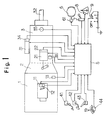
- Fig. 1 is a block diagram showing an embodiment of a vehicle clutch control system according to the present invention.
- numeral 1 denotes an internal combustion engine mounted in an automotive vehicle for burning fuel to produce a driving force by the combustion energy.
- Numeral 11 denotes an engine actuator for actuating a fuel injection pump or throttle valve serving as means for supplying fuel to the engine 1.
- Numeral 12 denotes a throttle opening sensor for sensing the actuation position of the engine actuator 11, and 13 an engine rotation sensor for sensing the rotational speed of the engine 1.
- Numeral 2 denotes a friction clutch, such as a dry-type, single-disk clutch, which transmits the driving torque of the engine to a transmission 3. Engagement/disengagement of the clutch for transmitting and interrupting the driving torque is controlled by a clutch actuator 21.
- Numeral 22 denotes a clutch stroke sensor for sensing the engaging state of the clutch 2 by sensing the actuation position of the clutch actuator 21. The output of the clutch stroke sensor 22 is delivered to the controller 5.
- the transmission 3 is constituted by a counter-shaft gear-type transmission and is adapted to apply shift control to each gear stage by a shift actuator 31.
- Numeral 33 denotes an input shaft rotation sensor for sensing the rotational speed of the input shaft of the transmission 3, 35 a vehicle velocity sensor for sensing the rotational speed of an output shaft 32 of the transmission 3, and 34 a gear stage sensor attached to the shift actuator 31 for sensing the gear stage of the transmission 3. The outputs of these sensors are delivered to the controller 5.
- Numeral 41 denotes an accelerator sensor for sensing the amount of depression of the accelerator pedal, 42 a brake sensor for sensing the amount of depression of the foot brake, 43 a parking brake switch for sensing operation of the parking brake, and 44 a selection switch for sensing the selection position (e.g., the D range, I, II, III ranges and Reverse range) of a select lever.
- the outputs of these sensors and switches are applied to the controller 5.
- Numeral 6 denotes a brake device for applying braking force to a wheel of the vehicle
- numeral 61 designates a braking force maintaining device (for example, see USP 4,618,040) arranged in the hydraulic circuit of the brake device 6.
- the braking force maintaining device 61 responds to a command from the controller 5 by actuating an electromagnetic check valve arranged in the brake hydraulic circuit.
- the braking force maintaining device 61 responds to a command from the controller 5 by deactuating the electromagnetic check valve to release the braking force.
- the device 61 is used as means for aiding forward propulsion of the vehicle on an upgrade.
- Numeral 7 denotes a load status switch for setting the status of a load carried by the vehicle.
- the switch 7 is provided at the driver's seat and is changed over by the driver depending upon whether the vehicled is loaded or empty.
- the switch 7 is connected to an input port on the controller 5.
- Numeral 8 denotes a gradient sensor mounted on the vehicle body to detect the slope of the road surface on which the vehicle is traveling.
- Numeral 9 designates a creep adjusting device mounted at the driver's seat. This device is adjusted by the driver to set a desired creep strength when the vehicle creeps in the half-clutch state. The device can be used also to turn off the creep function.
- the outputs of the gradient sensor 8 and creep adjusting device 9 are applied to the controller 5.
- the creep adjusting device 9 can employ a poteniometer-type variable resistor and need not be the multiple-stage switch shown in Fig. 1.
- the controller 5 is constituted by a microcomputer and has a central controller for performing processing, various memories for storing processing procedures, control procedures and control maps, described below, and an input/output port.
- the controller 5 sends commands to the associated actuators and the like in accordance with results obtained from the stored procedures, thereby controlling the clutch 2, transmission 3, brake device, etc.
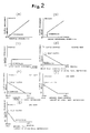
- Figs. 2(a) through (g) show various maps stored in the memory of the controller 5.
- Figs. 2(a) through (c) are maps for setting the amount of clutch engagement during ordinary travel of the vehicle, in which (a) is for setting the relation between throttle opening and clutch engagement amount A, (b) is for setting the relation between engine rpm and clutch engagement amount B, and (c) is for setting the relation between input shaft rpm and clutch engagement amount C.
- Figs. 2(d) through (g) are maps for vehicle travel at very low velocity. These are for setting the relation between braking force, namely the amount of brake pedal depression, and clutch engagement amount D at each gear speed of the transmission.
- FIG. 2(d) is for setting clutch engagement amount D in reverse gear, (e) in first gear, (f) in second gear, and (g) in third gear.
- the map for first gear in Fig. 2(e) is used when the vehicle is in the loaded state or traveling on an upgrade. Clutch engagement starts when the braking force of the brake is high, namely when the brake pedal is returned slightly from the full-stroke position. Driving force also is large owing to the low-speed gear, and the amount of clutch engagement is large in comparison with the second and third gears.
- the map for reverse gear in Fig. 2(d) similar to that described above, also is used in a state where the driving force is large and the vehicle is carring a load. Accordingly, the clutch starts to be engaged when the brake pedal is returned slightly from the full-stroke position.
- Fig. 3 is a processing flowchart illustrating an example of operation according to the present embodiment. The operation of this embodiment will now be described based on Fig. 3.
- step S1 the controller 5 determines, in accordance with a signal from the accelerator sensor 41, whether the accelerator pedal is being depressed. When it is determined that the accelerator pedal is being depressed, this means that the vehicle is traveling in the ordinary manner, and processing proceeds to step S2.
- the controller reads in the throttle opening signal from the throttle opening sensor 12 provided on the engine actuator 11 and determines, by retrieving the map (a) stored in memory, the clutch engagement amount A corresponding to the throttle opening. The program then proceeds to step S3.
- step S3 the controller reads in the rpm signal signal from the engine rotation sensor 13 and determines, by retrieving the map (b), the clutch engagement amount B corresponding to this rotational speed.
- step S4 the controller reads in the rpm signal signal from the input shaft rotation sensor 33 and determines, by retrieving the map (c), the clutch engagement amount C corresponding to this rotational speed. The program then proceeds to step S5.
- the controller 5 proceeds to step S18 to control the clutch actuator 21 in such a manner that the clutch engagement amount X decided at step S5 will be achieved.
- step S6 is the beginning of flow for controlling travel finely at very low velocity.
- the controller 5 determines at step S6, based on the signal from the braking force maintaining device 61, whether maintenance of braking force is in effect. If braking is being maintained, the clutch engagement amount D is made zero at step S17. If it is found at step S6 that braking force is not being maintained, then the signal from the parking brake switch 43 is checked at step S7. The program proceeds to step S17 if the parking brake is in operation. If the parking brake is found not to be in operation at step S7, the program proceeds to step S8. Since the setting of the clutch engagement amount D versus braking force differs with each gear speed of the transmission, the gear speed signals from the gear speed sensors 34 are read in.
- step S8 If the gear speed signal is indicative of reverse (Rev.), the program proceeds from step S8 to step S12, where the map (d) for reverse is retrieved to obtain the clutch engagement amount D corresponding to the braking force from the brake sensor 42. If the gear speed signal is indicative of first gear (1st), then the program proceeds from step S9 to step S13, where the map (e) for first gear is retrieved to obtain the clutch engagement amount D corresponding to the braking force. If the gear speed signal is indicative of second gear (2nd), then the program proceeds from step S10 to step S14, where the map (f) for second gear is retrieved to obtain the clutch engagement amount D corresponding to the braking force.
- step S11 If the gear speed signal is indicative of third gear (3rd), then the program proceeds from step S11 to step S15, where the map (g) for third gear is retrieved to obtain the clutch engagement amount D corresponding to the braking force.
- the clutch engagement amount D which differs depending upon the transmission speed, is obtained.
- step S16 the clutch engagment amount D obtained through steps S12 - S15 is decided as the clutch engagement amount X, after which the program proceeds to step S18, where the clutch actuator is controlled in such a manner that the clutch engagement amount S is achieved.
- the arrangement is such that when the vehicle travels at very low velocity, ultra-low velocity control is performed merely be controlling the amount by which the brake pedal is depressed.
- the clutch engagement amount with respect to braking force is set for each and every gear speed. Therefore, since the amount of clutch engagement corresponds to driving force, smooth travel at very low velocity can be achieved and abnormal wear of the clutch-driven plate can be prevented.
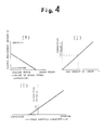
- Fig. 4 illustrates maps (h) - (j) used in another embodiment of the present invention, in which (h) is for setting the relation between driving force and a clutch engagement amount D′ and applies to maps (d) through (g) described earlier, (i) is for setting a corrective value of clutch engagement amount to take road surface gradient into account, and (j) is for setting a corrective value of clutch engagement amount with regard to a creep adjusting device, which is for adjusting creep strength.
- These maps are stored in the memory of the controller 5.
- Fig. 5 is a processing flowchart illustrating another example of operation according to the present embodiment. The operation of this embodiment will now be described based on Fig. 5.
- step P6 a flag is cleared if the flag has been set, and the program proceeds to step P24.
- the clutch actuator controlled in such a manner that the clutch engagement amount X′ decided at step P5 is achieved.
- step P7 is the beginning of flow for controlling travel finely at very low velocity.
- the controller 5 determines at step P7, based on the status of the braking force maintaining device 61, whether maintenance of braking force is in effect. If braking force is not being maintained, the parking brake is found not to be in operation at step P8 and the creep adjusting device 9 is found at step P9 not to be set in the off position, then parking brake switch is checked at step P10. When YES answer is received at step P7, P8 or P9, the program proceeds to step P23, where the clutch engagement amount D′ is made zero.
- step P12 when the parking brake is found to be released at step P10 based on a signal from the parking brake switch 43, or when it is found at step P11, based on a signal from the selection switch 44, that the transmission gear speed is changed from neutral (a gear at which no travel takes place) to a travel gear.
- a flag for prohibiting creep (half clutch) at the time of brake release is controlled and set (to inhibit creep). The reason for this is that when the parking brake is suddenly released or the select lever operated, the controller cannot determine whether the driver wishes to begin traveling immediately or is preparing to do so. Thus, this step prevents the vehicle from lurching forward unexpectedly.
- step P13 the controller checks the amount of brake pedal depression based on the signal from the brake sensor 42. If the braking force (the amount of brake pedal depression) does not exceed a set value (i.e., if the braking force is insufficient), the program proceeds to step P15. If the brake pedal is found to be pressed sufficiently at step P13, the flag is cleared at step P14 (creep is allowed) and the program proceeds to step P15.
- step P23 it is determined at this step whether the flag has been set. If the flag has been set, the program proceeds to step P23 to make the clutch engagement amount D′ zero. If the flag has not been set, the program proceeds to the flow from step P16 onward.
- step P16 The signal from the brake sensor 42 is read in and the map of Fig. 4(h) is retrieved at step P16 to obtain the clutch engagement amount D′.
- step P17 at which the signal from the gradient sensor 8 is read in and the map (i) retrieved to obtain a corrective value E of clutch engagement amount with respect to road surface slope.
- step P18 the signal from the creep adjusting device 9 is read in and the map (j) is retrieved to obtain a corrective value F of clutch engagement amount with respect to the set amount of creep.
- step P19 the signal from the load status switch 7 is checked. If the vehicle is not carrying a load, a corrective value G of the clutch engagement amount is made a preset value I. If the vehicle is carrying a load, the corrective value G is made a set value II (steps P20, P21).
- the clutch actuator 21 is controlled so as to achieve the obtained clutch engagement amount X', and the vehicle is make to travel at very low velocity in the half-clutch state.
- travel at very low velocity can be achieved with ease merely by controlling the amount of brake pedal depression, and the amount of clutch engagment can be corrected in dependence upon the state of the road surface on which the vehicle is situated, the desired amount of adjustment set by the creep adjusting device, and the state of the vehicle load. This makes smooth travel at very low velocities possible.
Description
- This invention relates to a control system for a clutch disposed between an engine and a transmission mounted on an automotive vehicle.
- In order to facilitate the driving of automotive vehicles, automatic transmissions have been developed and put into use in which a conventional friction clutch or counter-shaft gear-type transmission is utilized and engagement/disengagement of the friction clutch or a speed change in the transmission is controlled by an electronic control unit using a microcomputer.
- A control system which decides a target position of an amount of clutch engagement in an automatic transmission using such an electronic control unit has been disclosed in the specification of Japanese Patent Application Laid-Open (KOKAI) No. 63-61644 and includes a load sensor for sensing engine throttle opening, an engine rotation sensor for sensing the rotational speed (rpm) of the engine, an input shaft rotation sensor for sensing the rotational speed of the input shaft of a transmission, and a clutch actuator which controls the engagement of a friction clutch, wherein maps associated with these three sensors are retrieved based on signals from the sensors serving as information indicative of the vehicle load, the corresponding amount of clutch engagement is obtained and the clutch actuator is driven accordingly.
- When a vehicle equipped with an automatic transmission for controlling a disk clutch in accordance with the foregoing proposal is parked in a lot or at a curb, the friction clutch will not grip. For this reason, the vehicle is controlled at very low velocity by stepping down on the accelerator pedal and foot brake in very small amounts. When a load is carried in and out by a truck or the like, it is necessary for the truck to make small movements on the order of several centimetres relative to a loading platform. In such case the driver must quickly alternate between the accelerator pedal and brake pedal. If there is a delay in switching from one pedal to the other, the vehicle may contact the platform or some obstruction and sustain damage.
- EP-A-0 239 416 (corresponding to the preamble of claim 1) discloses a system for controlling an automatic clutch in which the clutch is disengaged during braking when the vehicle engine speed falls below a minimum threshold.
- An object of the present invention is to provide a vehicle clutch control system with which an automotive vehicle can be made to travel easily and smoothly at very low velocity by manipulating solely a brake pedal.
- According to the present invention, there is provided a vehicle clutch control system for an automotive vehicle having an engine, a transmission, a clutch disposed between the engine and the transmission, a brake device for causing a braking force to act upon wheels of the vehicle, and an accelerator pedal, the system comprising:
a clutch actuator for engaging and disengaging the clutch;
means for controlling the clutch actuator;
means for detecting the braking force applied by the braking device; and,
an accelerator pedal sensor for sensing the amount of depression of the accelerator pedal; characterised by:
clutch engagement deciding means for deciding an amount of clutch engagement based on the braking force applied by the brake device when the accelerator pedal sensor senses that the accelerator pedal is not depressed whereby fine control of movement of the vehicle at low speed is obtained solely by depression and release of the brake pedal. - Other features and advantages of the present invention will be apparent from the following description taken in conjunction with the accompanying drawings, in which like reference characters designate the same or similar parts throughout the figures thereof.
- In the drawings:
- Fig. 1 is a block diagram showing an embodiment of a vehicle clutch control system according to the present invention;
- Figs. 2(a), (b) and (c) are diagrams for describing control maps for setting the amount of engagement of a clutch when an automotive vehicle is travelling in an ordinary manner;
- Figs. 2(d), (e), (f) and (g) are diagrams for describing control maps, which are used in the present invention, for setting the amount of engagement of a clutch when an automotive vehicle is travelling at very low velocity;
- Fig. 3 is a processing flowchart illustrating an example of control performed by the vehicle clutch control system of the present invention;
- Fig. 4(h) is a diagram for describing another example of a control map, used in the present invention, for setting an amount of clutch engagement when an automotive vehicle is traveling at very low velocity;
- Figs. 4(i), (j) are diagrams for describing control maps for setting corrective values of the amount of clutch engagement; and
- Fig 5 is a processing flowchart illustrating another example of control performed by the vehicle clutch control system of the present invention.
- An embodiment of a valve control system is an internal combustion engine in accordance with the present invention will now be described in detail with reference to the drawings.
- Fig. 1 is a block diagram showing an embodiment of a vehicle clutch control system according to the present invention.
- In Fig. 1,
numeral 1 denotes an internal combustion engine mounted in an automotive vehicle for burning fuel to produce a driving force by the combustion energy. Numeral 11 denotes an engine actuator for actuating a fuel injection pump or throttle valve serving as means for supplying fuel to theengine 1. Numeral 12 denotes a throttle opening sensor for sensing the actuation position of theengine actuator engine 1. These sensors supply their output signals to acontroller 5, described below. - Numeral 2 denotes a friction clutch, such as a dry-type, single-disk clutch, which transmits the driving torque of the engine to a
transmission 3. Engagement/disengagement of the clutch for transmitting and interrupting the driving torque is controlled by aclutch actuator 21. Numeral 22 denotes a clutch stroke sensor for sensing the engaging state of theclutch 2 by sensing the actuation position of theclutch actuator 21. The output of theclutch stroke sensor 22 is delivered to thecontroller 5. - The
transmission 3 is constituted by a counter-shaft gear-type transmission and is adapted to apply shift control to each gear stage by ashift actuator 31. Numeral 33 denotes an input shaft rotation sensor for sensing the rotational speed of the input shaft of thetransmission 3, 35 a vehicle velocity sensor for sensing the rotational speed of anoutput shaft 32 of thetransmission 3, and 34 a gear stage sensor attached to theshift actuator 31 for sensing the gear stage of thetransmission 3. The outputs of these sensors are delivered to thecontroller 5. - Numeral 41 denotes an accelerator sensor for sensing the amount of depression of the accelerator pedal, 42 a brake sensor for sensing the amount of depression of the foot brake, 43 a parking brake switch for sensing operation of the parking brake, and 44 a selection switch for sensing the selection position (e.g., the D range, I, II, III ranges and Reverse range) of a select lever. The outputs of these sensors and switches are applied to the
controller 5. - Numeral 6 denotes a brake device for applying braking force to a wheel of the vehicle, and
numeral 61 designates a braking force maintaining device (for example, see USP 4,618,040) arranged in the hydraulic circuit of the brake device 6. In order for braking force to be maintained when the brake pedal is depressed to actuate the brake device and stop the vehicle, the brakingforce maintaining device 61 responds to a command from thecontroller 5 by actuating an electromagnetic check valve arranged in the brake hydraulic circuit. When the accelerator pedal is depressed to propel the vehicle forward and the clutch attains a prescribed state of engagement, the brakingforce maintaining device 61 responds to a command from thecontroller 5 by deactuating the electromagnetic check valve to release the braking force. Thus thedevice 61 is used as means for aiding forward propulsion of the vehicle on an upgrade. - Numeral 7 denotes a load status switch for setting the status of a load carried by the vehicle. The switch 7 is provided at the driver's seat and is changed over by the driver depending upon whether the vehicled is loaded or empty. The switch 7 is connected to an input port on the
controller 5. - Numeral 8 denotes a gradient sensor mounted on the vehicle body to detect the slope of the road surface on which the vehicle is traveling. Numeral 9 designates a creep adjusting device mounted at the driver's seat. This device is adjusted by the driver to set a desired creep strength when the vehicle creeps in the half-clutch state. The device can be used also to turn off the creep function. The outputs of the
gradient sensor 8 and creep adjusting device 9 are applied to thecontroller 5. The creep adjusting device 9 can employ a poteniometer-type variable resistor and need not be the multiple-stage switch shown in Fig. 1. - The
controller 5 is constituted by a microcomputer and has a central controller for performing processing, various memories for storing processing procedures, control procedures and control maps, described below, and an input/output port. When signals arrive from the aforementioned sensors and switches, thecontroller 5 sends commands to the associated actuators and the like in accordance with results obtained from the stored procedures, thereby controlling theclutch 2,transmission 3, brake device, etc. - Figs. 2(a) through (g) show various maps stored in the memory of the
controller 5. Figs. 2(a) through (c) are maps for setting the amount of clutch engagement during ordinary travel of the vehicle, in which (a) is for setting the relation between throttle opening and clutch engagement amount A, (b) is for setting the relation between engine rpm and clutch engagement amount B, and (c) is for setting the relation between input shaft rpm and clutch engagement amount C. Figs. 2(d) through (g) are maps for vehicle travel at very low velocity. These are for setting the relation between braking force, namely the amount of brake pedal depression, and clutch engagement amount D at each gear speed of the transmission. Fig. 2(d) is for setting clutch engagement amount D in reverse gear, (e) in first gear, (f) in second gear, and (g) in third gear. The map for first gear in Fig. 2(e) is used when the vehicle is in the loaded state or traveling on an upgrade. Clutch engagement starts when the braking force of the brake is high, namely when the brake pedal is returned slightly from the full-stroke position. Driving force also is large owing to the low-speed gear, and the amount of clutch engagement is large in comparison with the second and third gears. There are cases where the map for reverse gear in Fig. 2(d), similar to that described above, also is used in a state where the driving force is large and the vehicle is carring a load. Accordingly, the clutch starts to be engaged when the brake pedal is returned slightly from the full-stroke position. - (f) The map for second speed shown in Fig. 2(f) is used on level road surfaces regardless of whether the vehicle is or is not carrying a load. Since a large driving force is unnecessary, the clutch starts to be engaged after the brake pedal is returned a considerable amount. The vehicle creeps forward even when the amount of clutch engagement becomes small. The map for third gear shown in Fig. 2(g) is hardly ever used for parking since speed develops owing to the gear ratio. This map can be employed when the vehicle is traveling unloaded or on a downgrade.
- The maps for each of these gear speeds shown in Figs. 2(d) through (g) are such that driving force differs depending upon each gear ratio. Therefore, since the driving force is smaller for third gear than for first gear, by way of example, the engine will stall or the time for slip between the engine flywheel (drive-shaft side) and clutch-driven plate (driven-side) will be prolonged if the amount of clutch engagement is made large. Consequently, the clutch-driven plate tends to sustain abnormal wear or thermal deformation, and velocity during creep rises in the half-clutch state. In a gear speed where driving force is small, therefore, the amount of clutch engagement is made small.
- Fig. 3 is a processing flowchart illustrating an example of operation according to the present embodiment. The operation of this embodiment will now be described based on Fig. 3.
- First, as step S1, the
controller 5 determines, in accordance with a signal from theaccelerator sensor 41, whether the accelerator pedal is being depressed. When it is determined that the accelerator pedal is being depressed, this means that the vehicle is traveling in the ordinary manner, and processing proceeds to step S2. Here the controller reads in the throttle opening signal from thethrottle opening sensor 12 provided on theengine actuator 11 and determines, by retrieving the map (a) stored in memory, the clutch engagement amount A corresponding to the throttle opening. The program then proceeds to step S3. - At step S3 the controller reads in the rpm signal signal from the
engine rotation sensor 13 and determines, by retrieving the map (b), the clutch engagement amount B corresponding to this rotational speed. At step S4 the controller reads in the rpm signal signal from the inputshaft rotation sensor 33 and determines, by retrieving the map (c), the clutch engagement amount C corresponding to this rotational speed. The program then proceeds to step S5. - The clutch engagement amounts A, B, C obtained respectively at the steps S2, S3, S4 are added at step S5 to compute and decide a clutch engagement amount

controller 5 proceeds to step S18 to control theclutch actuator 21 in such a manner that the clutch engagement amount X decided at step S5 will be achieved. - If it is decided at step S1 that the accelerator pedal is not being depressed, then the program proceeds to step S6, which is the beginning of flow for controlling travel finely at very low velocity. The
controller 5 determines at step S6, based on the signal from the brakingforce maintaining device 61, whether maintenance of braking force is in effect. If braking is being maintained, the clutch engagement amount D is made zero at step S17. If it is found at step S6 that braking force is not being maintained, then the signal from theparking brake switch 43 is checked at step S7. The program proceeds to step S17 if the parking brake is in operation. If the parking brake is found not to be in operation at step S7, the program proceeds to step S8. Since the setting of the clutch engagement amount D versus braking force differs with each gear speed of the transmission, the gear speed signals from thegear speed sensors 34 are read in. - If the gear speed signal is indicative of reverse (Rev.), the program proceeds from step S8 to step S12, where the map (d) for reverse is retrieved to obtain the clutch engagement amount D corresponding to the braking force from the
brake sensor 42. If the gear speed signal is indicative of first gear (1st), then the program proceeds from step S9 to step S13, where the map (e) for first gear is retrieved to obtain the clutch engagement amount D corresponding to the braking force. If the gear speed signal is indicative of second gear (2nd), then the program proceeds from step S10 to step S14, where the map (f) for second gear is retrieved to obtain the clutch engagement amount D corresponding to the braking force. If the gear speed signal is indicative of third gear (3rd), then the program proceeds from step S11 to step S15, where the map (g) for third gear is retrieved to obtain the clutch engagement amount D corresponding to the braking force. Thus, the clutch engagement amount D, which differs depending upon the transmission speed, is obtained. - At step S16, the clutch engagment amount D obtained through steps S12 - S15 is decided as the clutch engagement amount X, after which the program proceeds to step S18, where the clutch actuator is controlled in such a manner that the clutch engagement amount S is achieved.
- In accordance with this embodiment as set forth above, the arrangement is such that when the vehicle travels at very low velocity, ultra-low velocity control is performed merely be controlling the amount by which the brake pedal is depressed. As a result, driving along a very narrow road, parking and approaching a loading platform can readily be performed through a simple operation.
- Further, in accordance with the embodiment, the clutch engagement amount with respect to braking force is set for each and every gear speed. Therefore, since the amount of clutch engagement corresponds to driving force, smooth travel at very low velocity can be achieved and abnormal wear of the clutch-driven plate can be prevented.
- Fig. 4 illustrates maps (h) - (j) used in another embodiment of the present invention, in which (h) is for setting the relation between driving force and a clutch engagement amount D′ and applies to maps (d) through (g) described earlier, (i) is for setting a corrective value of clutch engagement amount to take road surface gradient into account, and (j) is for setting a corrective value of clutch engagement amount with regard to a creep adjusting device, which is for adjusting creep strength. These maps are stored in the memory of the
controller 5. - Fig. 5 is a processing flowchart illustrating another example of operation according to the present embodiment. The operation of this embodiment will now be described based on Fig. 5.
- Steps P1 through p5 are for when the vehicle is traveling in an ordinary manner, just as in steps S1 through S5 of Fig. 3. Therefore, in accordance with the signals from the
throttle opening sensor 12,engine rotation sensor 13 and inputshaft rotation sensor 33, the maps (a) through (c) are retrieved to obtain the clutch engagement amounts A, B, C, and the clutch engagement amount is computed and decided.
- Next, at step P6, a flag is cleared if the flag has been set, and the program proceeds to step P24. The clutch actuator controlled in such a manner that the clutch engagement amount X′ decided at step P5 is achieved.
- If it is determined at step P1 that the accelerator pedal is not being depressed, then the program proceeds to step P7, which is the beginning of flow for controlling travel finely at very low velocity. The
controller 5 determines at step P7, based on the status of the brakingforce maintaining device 61, whether maintenance of braking force is in effect. If braking force is not being maintained, the parking brake is found not to be in operation at step P8 and the creep adjusting device 9 is found at step P9 not to be set in the off position, then parking brake switch is checked at step P10. When YES answer is received at step P7, P8 or P9, the program proceeds to step P23, where the clutch engagement amount D′ is made zero. - The program proceeds to step P12 when the parking brake is found to be released at step P10 based on a signal from the
parking brake switch 43, or when it is found at step P11, based on a signal from theselection switch 44, that the transmission gear speed is changed from neutral (a gear at which no travel takes place) to a travel gear. At step P12, a flag for prohibiting creep (half clutch) at the time of brake release is controlled and set (to inhibit creep). The reason for this is that when the parking brake is suddenly released or the select lever operated, the controller cannot determine whether the driver wishes to begin traveling immediately or is preparing to do so. Thus, this step prevents the vehicle from lurching forward unexpectedly. - If NO answers are obtained at both steps P10 and P11, or after the flag has been set at step P12, the program proceeds to step P13, at which the controller checks the amount of brake pedal depression based on the signal from the
brake sensor 42. If the braking force (the amount of brake pedal depression) does not exceed a set value (i.e., if the braking force is insufficient), the program proceeds to step P15. If the brake pedal is found to be pressed sufficiently at step P13, the flag is cleared at step P14 (creep is allowed) and the program proceeds to step P15. - It is determined at this step whether the flag has been set, If the flag has been set, the program proceeds to step P23 to make the clutch engagement amount D′ zero. If the flag has not been set, the program proceeds to the flow from step P16 onward.
- The signal from the
brake sensor 42 is read in and the map of Fig. 4(h) is retrieved at step P16 to obtain the clutch engagement amount D′. This is followed by step P17, at which the signal from thegradient sensor 8 is read in and the map (i) retrieved to obtain a corrective value E of clutch engagement amount with respect to road surface slope. Then, at step P18, the signal from the creep adjusting device 9 is read in and the map (j) is retrieved to obtain a corrective value F of clutch engagement amount with respect to the set amount of creep. - Next, at step P19, the signal from the load status switch 7 is checked. If the vehicle is not carrying a load, a corrective value G of the clutch engagement amount is made a preset value I. If the vehicle is carrying a load, the corrective value G is made a set value II (steps P20, P21).
- This is followed by step P22, at which a clutch engagement amount

- The
clutch actuator 21 is controlled so as to achieve the obtained clutch engagement amount X', and the vehicle is make to travel at very low velocity in the half-clutch state. - In accordance with the present embodiment as set forth above, travel at very low velocity can be achieved with ease merely by controlling the amount of brake pedal depression, and the amount of clutch engagment can be corrected in dependence upon the state of the road surface on which the vehicle is situated, the desired amount of adjustment set by the creep adjusting device, and the state of the vehicle load. This makes smooth travel at very low velocities possible.
- As many apparently widely different embodiments of the present invention can be made without departing from the spirit and scope thereof, it is to be understood that the invention is not limited to the specific embodiments thereof except as defined in the appended claims.
Claims (5)
- A vehicle clutch control system for an automotive vehicle having an engine (1), a transmission (3), a clutch (2) disposed between the engine and the transmission, a brake device (6) for causing a braking force to act upon wheels of the vehicle, and an accelerator pedal, the system comprising:
a clutch actuator (21) for engaging and disengaging the clutch (2);
means (5) for controlling the clutch actuator (21);
means (61) for detecting the braking force applied by the braking device (6); and,
an accelerator pedal sensor (41) for sensing the amount of depression of the accelerator pedal;
characterised by:
clutch engagement deciding means (5) for deciding an amount of clutch engagement based on the braking force applied by the brake device when the accelerator pedal sensor (41) senses that the accelerator pedal is not depressed whereby fine control of movement of the vehicle at low speed is obtained solely by depression and release of the brake pedal. - A system according to claim 1, further comprising gear speed detecting means (34) for detecting an operating gear speed of the transmission, wherein the clutch engagement amount deciding means has control maps for setting a clutch engagement amount corresponding to a braking force for each gear speed, with the clutch engagement amount being set based on a control map of a gear speed detected by the gear speed detecting means.
- A system according to claim 1 or claim 2, further comprising road gradient detecting means (8) for detecting the gradient of a road surface on which the vehicle is situated, wherein the clutch engagement amount deciding means has means for setting a corrective value corresponding to the gradient of the road surface, with a clutch engagement amount set based on braking force being corrected by a corrective value corresponding to the road surface gradient detected by the road gradient detecting means.
- A system according to any of claims 1 to 3, further comprising creep adjusting means (9) for adjusting an amount of creep, wherein the clutch engagement amount deciding means has means for setting a corrective value corresponding to a set creep amount, with a clutch engagement amount set based on braking force being corrected by a corrective value corresponding to a signal from the creep adjusting means.
- A system according to any of claims 1 to 4, further comprising load status setting means (7) for setting the status of a load on the vehicle, wherein the clutch engagement amount deciding means has means for setting a corrective value corresponding to the status of a load, with a clutch engagement amount set based on braking force being corrected by a corrective value corresponding to a signal from the load status setting means.
Applications Claiming Priority (2)
| Application Number | Priority Date | Filing Date | Title |
|---|---|---|---|
| JP32153288A JP2748470B2 (en) | 1988-12-20 | 1988-12-20 | Automatic transmission for vehicles |
| JP321532/88 | 1988-12-20 |
Publications (3)
| Publication Number | Publication Date |
|---|---|
| EP0375162A2 EP0375162A2 (en) | 1990-06-27 |
| EP0375162A3 EP0375162A3 (en) | 1991-07-31 |
| EP0375162B1 true EP0375162B1 (en) | 1995-01-25 |
Family
ID=18133618
Family Applications (1)
| Application Number | Title | Priority Date | Filing Date |
|---|---|---|---|
| EP89312121A Expired - Lifetime EP0375162B1 (en) | 1988-12-20 | 1989-11-22 | Vehicle clutch control system |
Country Status (4)
| Country | Link |
|---|---|
| US (1) | US5020645A (en) |
| EP (1) | EP0375162B1 (en) |
| JP (1) | JP2748470B2 (en) |
| DE (1) | DE68920850T2 (en) |
Cited By (4)
| Publication number | Priority date | Publication date | Assignee | Title |
|---|---|---|---|---|
| DE19639293C1 (en) * | 1996-09-25 | 1998-04-02 | Daimler Benz Ag | Automatic control of a clutch |
| DE10105749A1 (en) * | 2001-02-08 | 2002-08-14 | Man Nutzfahrzeuge Ag | Method for assisting in the parking of a commercial vehicle, involves the operation of the clutch and brake automatically in harmony as a result of the accelerator pedal and load state when parking aid activated |
| US7041031B2 (en) | 2000-07-26 | 2006-05-09 | Eaton Corporation | Calculation of automated friction clutch urge torque on grades |
| DE102015226134A1 (en) | 2015-12-21 | 2017-06-22 | Zf Friedrichshafen Ag | Method for operating a motor vehicle |
Families Citing this family (48)
| Publication number | Priority date | Publication date | Assignee | Title |
|---|---|---|---|---|
| US5040648A (en) * | 1990-11-05 | 1991-08-20 | Caterpillar Inc. | Electrohydraulic control device for a drive train of a vehicle |
| FR2681561A1 (en) * | 1991-09-20 | 1993-03-26 | Renault | METHOD FOR CONTROLLING A VEHICLE EQUIPPED WITH AN AUTOMATIC OR SEMI-AUTOMATIC TRANSMISSION MECHANISM WITH SEMI-AUTOMATIC REPORTS, WHETHER OR NOT. |
| US5634867A (en) * | 1994-09-19 | 1997-06-03 | Eaton Corporation | Main clutch reengagement control for a double clutch downshift |
| DE19530612C2 (en) * | 1995-08-21 | 2002-06-27 | Daimler Chrysler Ag | Control of an automatic clutch |
| JP3596138B2 (en) * | 1996-01-29 | 2004-12-02 | トヨタ自動車株式会社 | Brake force control device for vehicle with starting clutch |
| DE19780343D2 (en) * | 1996-04-23 | 1998-08-20 | Luk Getriebe Systeme Gmbh | Device for controlling a torque transmission system |
| DE19711384B4 (en) * | 1996-05-17 | 2007-09-20 | Volkswagen Ag | Method for controlling the transmission of power in the transmission of a vehicle |
| US6033340A (en) * | 1996-05-24 | 2000-03-07 | Luk Getriebe-Systeme Gmbh | Method of and apparatus for operating a torque transmitting system in the power train of a motor vehicle |
| JP2847503B2 (en) * | 1996-09-27 | 1999-01-20 | 本田技研工業株式会社 | Control device for vehicle clutch |
| IT1288799B1 (en) * | 1996-11-05 | 1998-09-24 | Magneti Marelli Spa | CONTROL SYSTEM FOR PARKING AND DEPARTURE ON SLOPES OF A MOTOR VEHICLE. |
| GB2327108B (en) * | 1997-04-09 | 2002-04-10 | Luk Getriebe Systeme Gmbh | Motor vehicle with automatic clutch |
| NO981839L (en) * | 1997-04-30 | 1998-11-02 | Luk Getriebe Systeme Gmbh | Device for controlling a torque transfer system |
| US6167996B1 (en) * | 1997-12-10 | 2001-01-02 | Zf Meritor, Llc | Method and system for determining clutch status in a vehicle |
| GB9803436D0 (en) * | 1998-02-19 | 1998-04-15 | Ap Kongsberg Ltd | Clutch control systems |
| EP1065115B1 (en) * | 1999-07-02 | 2006-01-11 | Honda Giken Kogyo Kabushiki Kaisha | Driving force control unit for vehicles |
| GB2382113B (en) * | 2000-05-17 | 2004-07-28 | Luk Lamellen & Kupplungsbau | Method and device for automatically actuating a vehicle brake |
| GB0018187D0 (en) * | 2000-07-26 | 2000-09-13 | Eaton Corp | Improvements to low speed manoeuvring |
| DE10209839B4 (en) * | 2001-03-19 | 2016-09-22 | Schaeffler Technologies AG & Co. KG | Motor vehicle and method for operating a motor vehicle |
| DE10292346D2 (en) * | 2001-05-29 | 2004-04-15 | Luk Lamellen & Kupplungsbau | Method for setting the gripping point of a clutch actuated by a clutch actuator and control system |
| DE10223464A1 (en) * | 2001-06-05 | 2002-12-12 | Luk Lamellen & Kupplungsbau | Controlling and regulating process for automatic clutch and automatic transmission involves driver intervention to alter creep strategy |
| DE10225263B4 (en) * | 2001-06-13 | 2017-06-29 | Schaeffler Technologies AG & Co. KG | Method and device for controlling the creep behavior of a vehicle equipped with an automated clutch |
| DE10292823D2 (en) * | 2001-06-27 | 2004-05-27 | Luk Lamellen & Kupplungsbau | Method for changing the clutch torque of a clutch in the drive train of a vehicle with an automated manual transmission |
| DE10219420A1 (en) * | 2002-05-02 | 2003-11-13 | Zf Sachs Ag | Motor vehicle with creep function |
| DE102004006730A1 (en) * | 2003-02-12 | 2004-08-26 | Luk Lamellen Und Kupplungsbau Beteiligungs Kg | Safety method for carrying out a clutch safety strategy for a motor vehicle's automatic gearbox during an activated crawl function reduces thermal load on the clutch through activation criteria |
| DE10307462B4 (en) * | 2003-02-21 | 2019-02-28 | Robert Bosch Gmbh | Method for controlling the drive unit of a vehicle |
| JP4517597B2 (en) | 2003-05-23 | 2010-08-04 | トヨタ自動車株式会社 | Vehicle start control device |
| DE102004022380A1 (en) * | 2004-05-06 | 2005-12-01 | Adam Opel Ag | Motor vehicle, has operation brakes actuated by drivers, and control device which continuously closes clutch in opposite direction for rating actuation of operation brakes, during slow-down operation of brakes |
| US7332881B2 (en) * | 2004-10-28 | 2008-02-19 | Textron Inc. | AC drive system for electrically operated vehicle |
| JP4404313B2 (en) * | 2004-12-07 | 2010-01-27 | ヤンマー株式会社 | Control device for work vehicle |
| JP4550612B2 (en) * | 2005-02-18 | 2010-09-22 | 日立オートモティブシステムズ株式会社 | Control device, control method and control system for vehicle gear transmission |
| EP1928716A4 (en) * | 2005-09-08 | 2012-12-12 | Volvo Lastvagnar Ab | Method and device for controlling a clutch in a vehicle |
| ES2404309T3 (en) * | 2005-09-08 | 2013-05-27 | Volvo Lastvagnar Ab | Clutch control procedure and control to perform it |
| JP5503954B2 (en) * | 2009-12-14 | 2014-05-28 | 日立建機株式会社 | Clutch control device for work vehicle |
| DE102012015872A1 (en) * | 2012-08-09 | 2014-05-15 | Volkswagen Aktiengesellschaft | Circuit, method and computer program for controlling a creep mode |
| KR101393872B1 (en) * | 2012-10-30 | 2014-05-12 | 기아자동차주식회사 | Estimating method for transmitting torque of dry type clutch in vehicle |
| KR101393963B1 (en) | 2012-10-30 | 2014-05-12 | 기아자동차주식회사 | Estimating method for transmitting torque of dry type clutch in vehicle |
| JP6060195B2 (en) * | 2015-03-06 | 2017-01-11 | 本田技研工業株式会社 | Vehicle parking control device |
| US9944200B2 (en) * | 2015-03-09 | 2018-04-17 | Ford Global Technologies, Llc | Variable creep torque |
| US10316959B2 (en) | 2016-01-29 | 2019-06-11 | Cnh Industrial America Llc | System and method for controlling a work vehicle transmission based on the detection of unintended vehicle motion |
| US10086840B2 (en) * | 2016-07-29 | 2018-10-02 | Ford Global Technologies, Llc | Methods and system for operating a vehicle |
| JP2019015347A (en) * | 2017-07-07 | 2019-01-31 | スズキ株式会社 | Travel control device of vehicle |
| IT201700115964A1 (en) * | 2017-10-13 | 2019-04-13 | Cnh Ind Italia Spa | METHOD TO CHECK A TRANSMISSION PROVIDED WITH A BRAKING FUNCTIONALITY BY CLUTCH |
| DE102017219675A1 (en) * | 2017-11-06 | 2019-05-09 | Audi Ag | Method for operating a motor vehicle and motor vehicle |
| JP2022543513A (en) * | 2019-08-14 | 2022-10-13 | オートディン シス インコーポレイテッド | Clutch system linked with accelerator pedal and brake pedal |
| KR102231972B1 (en) * | 2019-10-08 | 2021-03-30 | 오토딘시스 주식회사 | Novel Power transmission device associated with excel and brake pedals |
| US11427204B2 (en) | 2020-01-29 | 2022-08-30 | Caterpillar Inc. | Control to mitigate operator abuse of drivetrain on grade |
| JP2022011031A (en) * | 2020-06-29 | 2022-01-17 | 株式会社クボタ | Work vehicle |
| DE102021203899A1 (en) | 2021-04-20 | 2022-10-20 | Zf Friedrichshafen Ag | Method for determining a control sequence of a powertrain |
Family Cites Families (7)
| Publication number | Priority date | Publication date | Assignee | Title |
|---|---|---|---|---|
| DE3208715A1 (en) * | 1982-03-11 | 1983-09-22 | Sachs Systemtechnik Gmbh | FREEWHEEL CONTROL DEVICE FOR A MOTOR VEHICLE CLUTCH |
| EP0127085A2 (en) * | 1983-05-27 | 1984-12-05 | Nissan Motor Co., Ltd. | Control device for hydraulic automatic clutch |
| US4732248A (en) * | 1985-06-10 | 1988-03-22 | Isuzu Motors Limited | Method of and apparatus for controlling automatic clutch |
| DE3674768D1 (en) * | 1985-07-26 | 1990-11-08 | Fujitsu Ltd | REVERSE DEVICE FOR FAST SWITCHING FORWARD OR REVERSE GEAR IN VEHICLE EQUIPPED WITH AUTOMATIC GEARBOX. |
| JPS62198530A (en) * | 1986-02-27 | 1987-09-02 | Aisin Seiki Co Ltd | Automatic clutch controller |
| JPS62227824A (en) * | 1986-03-28 | 1987-10-06 | Isuzu Motors Ltd | Clutch controller for vehicle mounted automatic clutch |
| JPS62292540A (en) * | 1986-06-12 | 1987-12-19 | Isuzu Motors Ltd | Brake force holding controller |
-
1988
- 1988-12-20 JP JP32153288A patent/JP2748470B2/en not_active Expired - Fee Related
-
1989
- 1989-11-21 US US07/439,330 patent/US5020645A/en not_active Expired - Fee Related
- 1989-11-22 EP EP89312121A patent/EP0375162B1/en not_active Expired - Lifetime
- 1989-11-22 DE DE68920850T patent/DE68920850T2/en not_active Expired - Fee Related
Cited By (7)
| Publication number | Priority date | Publication date | Assignee | Title |
|---|---|---|---|---|
| DE19639293C1 (en) * | 1996-09-25 | 1998-04-02 | Daimler Benz Ag | Automatic control of a clutch |
| US6077189A (en) * | 1996-09-25 | 2000-06-20 | Daimlerchrysler Ag | Automatic clutch with very slow speed |
| US7041031B2 (en) | 2000-07-26 | 2006-05-09 | Eaton Corporation | Calculation of automated friction clutch urge torque on grades |
| DE10105749A1 (en) * | 2001-02-08 | 2002-08-14 | Man Nutzfahrzeuge Ag | Method for assisting in the parking of a commercial vehicle, involves the operation of the clutch and brake automatically in harmony as a result of the accelerator pedal and load state when parking aid activated |
| DE10105749B4 (en) * | 2001-02-08 | 2010-12-30 | Man Nutzfahrzeuge Ag | Method for easier maneuvering in a commercial vehicle |
| DE102015226134A1 (en) | 2015-12-21 | 2017-06-22 | Zf Friedrichshafen Ag | Method for operating a motor vehicle |
| WO2017108309A1 (en) | 2015-12-21 | 2017-06-29 | Zf Friedrichshafen Ag | Method for operating a motor vehicle by creep mode of the clutch |
Also Published As
| Publication number | Publication date |
|---|---|
| JPH02168066A (en) | 1990-06-28 |
| EP0375162A3 (en) | 1991-07-31 |
| EP0375162A2 (en) | 1990-06-27 |
| JP2748470B2 (en) | 1998-05-06 |
| DE68920850D1 (en) | 1995-03-09 |
| DE68920850T2 (en) | 1995-06-08 |
| US5020645A (en) | 1991-06-04 |
Similar Documents
| Publication | Publication Date | Title |
|---|---|---|
| EP0375162B1 (en) | Vehicle clutch control system | |
| EP0130794B1 (en) | Electronic control method for vehicles | |
| US5681242A (en) | Selectable enhanced creep control mode for automated clutch and vehicular automated mechanical transmission system utilizing same | |
| EP1174303B1 (en) | Control method and system for vehicle starting | |
| EP1031487B1 (en) | Parking brake apparatus for industrial vehicle | |
| EP0205322B1 (en) | Method and apparatus for controlling an automatic clutch | |
| US5435795A (en) | Vehicle drivetrain control including CVT | |
| US5902210A (en) | Method and apparatus for controlling a vehicle | |
| EP1070625A2 (en) | Starting and driveline shock protection control method and system | |
| US6024673A (en) | Automatic clutch control for coasting with brake-condition responsive hysteresis width | |
| EP0426443A2 (en) | Engine-brake controller for vehicle with stepless speed-changer | |
| EP1310696B1 (en) | Automatic-clutch control system of automatic clutch type transmission | |
| CN110462263B (en) | Method and device for controlling gear shift in vehicle with transmission | |
| JP5150497B2 (en) | Method for driving an automatic or semi-automatic manual transmission for heavy vehicles in idling mode | |
| JP3492844B2 (en) | Automatic transmission for vehicles | |
| EP0323070A2 (en) | Integrated engine/clutch control | |
| EP1524456B1 (en) | Device for controlling a start of a vehicle | |
| EP3576998B1 (en) | Method for controlling a vehicle, computer program, computer readable medium and vehicle | |
| EP0290202B1 (en) | Device for controlling motor vehicle to run at constant speed | |
| JP2899511B2 (en) | Automatic transmission for vehicles | |
| JPH02159422A (en) | Clutch control device for automatic transmission | |
| EP1928716A1 (en) | Method and device for controlling a clutch in a vehicle | |
| JPH0243048B2 (en) | ||
| JPS61248947A (en) | Electronic control transmission for car | |
| JPH067962Y2 (en) | Vehicle automatic clutch control device |
Legal Events
| Date | Code | Title | Description |
|---|---|---|---|
| PUAI | Public reference made under article 153(3) epc to a published international application that has entered the european phase |
Free format text: ORIGINAL CODE: 0009012 |
|
| AK | Designated contracting states |
Kind code of ref document: A2 Designated state(s): DE GB |
|
| PUAL | Search report despatched |
Free format text: ORIGINAL CODE: 0009013 |
|
| AK | Designated contracting states |
Kind code of ref document: A3 Designated state(s): DE GB |
|
| 17P | Request for examination filed |
Effective date: 19920130 |
|
| 17Q | First examination report despatched |
Effective date: 19930603 |
|
| GRAA | (expected) grant |
Free format text: ORIGINAL CODE: 0009210 |
|
| AK | Designated contracting states |
Kind code of ref document: B1 Designated state(s): DE GB |
|
| REF | Corresponds to: |
Ref document number: 68920850 Country of ref document: DE Date of ref document: 19950309 |
|
| PLBE | No opposition filed within time limit |
Free format text: ORIGINAL CODE: 0009261 |
|
| STAA | Information on the status of an ep patent application or granted ep patent |
Free format text: STATUS: NO OPPOSITION FILED WITHIN TIME LIMIT |
|
| 26N | No opposition filed | ||
| PGFP | Annual fee paid to national office [announced via postgrant information from national office to epo] |
Ref country code: GB Payment date: 19971113 Year of fee payment: 9 |
|
| PG25 | Lapsed in a contracting state [announced via postgrant information from national office to epo] |
Ref country code: GB Free format text: LAPSE BECAUSE OF NON-PAYMENT OF DUE FEES Effective date: 19981122 |
|
| GBPC | Gb: european patent ceased through non-payment of renewal fee |
Effective date: 19981122 |
|
| PGFP | Annual fee paid to national office [announced via postgrant information from national office to epo] |
Ref country code: DE Payment date: 20031027 Year of fee payment: 15 |
|
| PG25 | Lapsed in a contracting state [announced via postgrant information from national office to epo] |
Ref country code: DE Free format text: LAPSE BECAUSE OF NON-PAYMENT OF DUE FEES Effective date: 20050601 |