EP0374976B1 - Device for limiting the collapse of a vehicle structure on frontal impact - Google Patents
Device for limiting the collapse of a vehicle structure on frontal impact Download PDFInfo
- Publication number
- EP0374976B1 EP0374976B1 EP89124017A EP89124017A EP0374976B1 EP 0374976 B1 EP0374976 B1 EP 0374976B1 EP 89124017 A EP89124017 A EP 89124017A EP 89124017 A EP89124017 A EP 89124017A EP 0374976 B1 EP0374976 B1 EP 0374976B1
- Authority
- EP
- European Patent Office
- Prior art keywords
- steering column
- cable
- vehicle
- body sides
- reinforcement plates
- Prior art date
- Legal status (The legal status is an assumption and is not a legal conclusion. Google has not performed a legal analysis and makes no representation as to the accuracy of the status listed.)
- Expired
Links
- 230000002787 reinforcement Effects 0.000 claims description 12
- 239000002184 metal Substances 0.000 claims description 3
- 238000000926 separation method Methods 0.000 description 2
- 230000005489 elastic deformation Effects 0.000 description 1
- 230000002250 progressing effect Effects 0.000 description 1
- 238000003466 welding Methods 0.000 description 1
Images
Classifications
-
- B—PERFORMING OPERATIONS; TRANSPORTING
- B62—LAND VEHICLES FOR TRAVELLING OTHERWISE THAN ON RAILS
- B62D—MOTOR VEHICLES; TRAILERS
- B62D21/00—Understructures, i.e. chassis frame on which a vehicle body may be mounted
- B62D21/15—Understructures, i.e. chassis frame on which a vehicle body may be mounted having impact absorbing means, e.g. a frame designed to permanently or temporarily change shape or dimension upon impact with another body
-
- B—PERFORMING OPERATIONS; TRANSPORTING
- B62—LAND VEHICLES FOR TRAVELLING OTHERWISE THAN ON RAILS
- B62D—MOTOR VEHICLES; TRAILERS
- B62D1/00—Steering controls, i.e. means for initiating a change of direction of the vehicle
- B62D1/02—Steering controls, i.e. means for initiating a change of direction of the vehicle vehicle-mounted
- B62D1/16—Steering columns
- B62D1/18—Steering columns yieldable or adjustable, e.g. tiltable
- B62D1/19—Steering columns yieldable or adjustable, e.g. tiltable incorporating energy-absorbing arrangements, e.g. by being yieldable or collapsible
- B62D1/197—Steering columns yieldable or adjustable, e.g. tiltable incorporating energy-absorbing arrangements, e.g. by being yieldable or collapsible incorporating devices for preventing ingress of the steering column into the passengers space in case of accident
Definitions
- This invention relates to a device for lifting the collapse of a vehicle structure on frontal impact, and in particular for limiting the movement of the body sides away from each other while at the same time also limiting the rearward movement of the steering column into the vehicle passenger compartment.
- vehicle body sides are connected together at their front by a cross-member of box structure, the opposing ends of which are welded or bolted directly to the body sides and/or to support brackets rigidly provided on the inner surfaces of these latter.
- Such a structure has the drawback of being relatively weak if the vehicle suffers frontal impact. In such a case, the stresses produced by the impact result in simultaneous tensile and torsion/shear stressing of the cross-member.
- the torsion and shear stresses are a maximum precisely at the points at which the cross-member is connected to the body sides, and this in the case of particularly violent impact can produce the partial or indeed total separation of the cross-member from the body sides by fracture of the weld spots and/or of the other connection means used, also cause generally the cross-member is fixed to the body sides by a relatively small number of weld spots and/or bolts, especially if little space is available so making the joining operations difficult and limiting the reliability and quality of the welds made.
- the object of the invention is to provide a simple, efficient and economical device for limiting the collapse of a vehicle structure on frontal impact, which is particularly able to limit the movement of the vehicle body sides away from each other, even if they become separated from the connecting cross-member.
- Said object is attained according to the invention by a device for limiting the collapse of a vehicle structure on impact, particularly on frontal impact, said structure comprising a pair of opposing body sides forming part of the vehicle body and laterally bounding the vehicle passenger compartment, and a steering column disposed parallel to the body sides, characterised by comprising a pair of reinforcement plates, each of which is rigidly fixed against a respective inner surface of a respective said body side, and a metal cable extending taut transversely to the passenger compartment and rigidly connecting said reinforcement plates together.
- the reference numeral 1 indicates overall a vehicle, in this case a motor vehicle, the structure 2 of which comprises a body, of which a pair of opposing body sides 5 form part, and a steering column 4 disposed parallel to the body sides 5.
- the pair of body sides 5 laterally bound a passenger compartment 6 of the vehicle 1, into which the steering column 4 projects by that end 8 provided with a steering wheel 9.
- the body sides 5 and steering column are interconnected by a device 10 arranged to limit the collapse of the structure 2, particularly in the case of frontal impact of the vehicle 1 against an obstacle and/or other vehicle.
- the device 10 comprises a pair of reinforcement plates 11 and 12, each of which is rigidly fixed against a respective inner surface 13 of a respective body side 5, and a metal cable 15 taut transversely to the passenger compartment 6 and rigidly connecting the reinforcement plates 11 and 12 together.
- These latter are of relatively large dimensions and are shaped so as to be able to be fixed easily to the body sides 5 by welding using a high number of weld spots, this latter facility being made possible by the fact that there is no cross-member connecting the body sides 5 together.
- the cable 15 is connected to the reinforcement plates 11 and 12 in moderately pretensioned manner, ie so that when under rest conditions it is under a predetermined tensile stress.
- the device 10 can comprise tensioning means 20 of any known type indicated diagrammatically merely as a block on the drawing, and connected mechanically in series with the cable 15.
- the cable 15 is inserted through respective fixing brackets 21 each rigid with a respective reinforcement plate 11, 12 and terminates as an endless loop at the tensioning means 20 which connect together the two ends 22 of the cable 15, this being preferably formed of wire strands.
- the cable 15 engages not only with the brackets 21 but also engages respective fixing means 25 for and rigid with the steering column 4 by passing in the manner of a loop about this latter.
- the fixing brackets 21 are disposed to the front of and in a position diametrically opposite the steering column fixing means 25, which comprise a pair of pulleys 30 fixed in mutually opposite positions to the side of the steering column 4, and a U-piece 31 fixed to the end 8 of the steering column 4 between the pulleys 30 and the steering wheel and having its concavity facing the pulleys 30.
- the cable 15 is arranged in such a manner as to define in plan view a closed annular figure comprising a first straight branch 40 taut between the fixing brackets 21 for the reinforcement plates 11, 12 and connecting together the opposing body sides 5, and a second and a third branch indicated respectively by 41 and 42 which are mutually oblique, opposite and asymmetrical, and extending taut between the fixing brackets 21, through which the cable 15 slidingly passes, and the pulleys 30, about which the branches 41 and 42 pass to form a common volute 44, which passes about the U-piece 31 so as to embrace the steering column in such a manner as to stress the cable 15, in particular the branch 40, should the steering column move towards the passenger compartment 6.
- the vehicle body 2 deforms such that the body sides 5 tend to move apart from each other to an extent which becomes progressively more pronounced in progressing towards the passenger compartment 6, and substantially a maximum precisely at the plates 11, 12.
- this movement apart is totally prevented (or at least considerably limited) because the branch 40 of the loop formed by the cable 15 opposes this movement and retains the body sides in position, while it itself becomes subjected to tensile stress with the result that the body sides can move only by the amount allowed by the elastic extension (or elastic-plastic if yield conditions are reached) of the cable 15, so totally limiting the collapse of the structure of the vehicle 1 while ensuring that at least part of the energy developed by the impact is absorbed, this being converted into deformation energy of the cable 15.
- the cable 15 is also able to prevent, or at least limit, any rearward movement of the steering column 4 because the tensile stress induced in the branch 40 by the attempted movement of the body sides 5 results in tension in the branches 41 and 42 in the direction of the arrows, with the result that an axial thrust is exerted on the steering column 4 in the direction of the arrow, ie in the opposite direction to that produced by the impact, even if this latter has not produced sufficient energy to produce for example the rearward movement of the vehicle engine-gearbox unit.
- the thrust transmitted by the impact to the steering column 4 is also discharged to the cable 15 to produce in the branch 40 a stress which opposes the moving-apart of the body sides 5.
- the impact stresses on the body sides 5 and steering column 4 are simultaneously discharged to the cable 15 and absorbed by the elastic deformation thereof, to limit or even prevent separation of the body sides 5 from the cross-members forming the load-bearing framework of the vehicle body 2.
- the cable 15 cannot become detached from the body sides 5 because as the plates are connected only to a cable, ie to an element of very small bulk, they can be made suitably large and be fixed to the body 2 by a large number of weld spots (or connection members), so ensuring that local stresses on them are absorbed.
- These stresses are in any case limited by the fact that the cable 15 is a very flexible element, so that it transmits only limited shear and torsional forces to the body sides 5.
Landscapes
- Engineering & Computer Science (AREA)
- Chemical & Material Sciences (AREA)
- Combustion & Propulsion (AREA)
- Transportation (AREA)
- Mechanical Engineering (AREA)
- Steering Controls (AREA)
- Body Structure For Vehicles (AREA)
- Arrangement Or Mounting Of Propulsion Units For Vehicles (AREA)
Description
- This invention relates to a device for lifting the collapse of a vehicle structure on frontal impact, and in particular for limiting the movement of the body sides away from each other while at the same time also limiting the rearward movement of the steering column into the vehicle passenger compartment. Currently, vehicle body sides are connected together at their front by a cross-member of box structure, the opposing ends of which are welded or bolted directly to the body sides and/or to support brackets rigidly provided on the inner surfaces of these latter. Such a structure has the drawback of being relatively weak if the vehicle suffers frontal impact. In such a case, the stresses produced by the impact result in simultaneous tensile and torsion/shear stressing of the cross-member. In particular, the torsion and shear stresses are a maximum precisely at the points at which the cross-member is connected to the body sides, and this in the case of particularly violent impact can produce the partial or indeed total separation of the cross-member from the body sides by fracture of the weld spots and/or of the other connection means used, also cause generally the cross-member is fixed to the body sides by a relatively small number of weld spots and/or bolts, especially if little space is available so making the joining operations difficult and limiting the reliability and quality of the welds made.
- It is also known, for example from German patent application No. 3627558, to limit the rearward movement of the steering column on frontal impact by connecting the steering column by a cable to the engine-gearbox unit so that the rearward movement of this latter on impact produces a forward pull on the steering column. However, such an arrangement is not always useful in the case of impact, particularly if the dynamics of the impact are such as to produce only a limited (or zero) movement of the engine-gearbox unit but at the same time a much greater movement of the steering column.
- The object of the invention is to provide a simple, efficient and economical device for limiting the collapse of a vehicle structure on frontal impact, which is particularly able to limit the movement of the vehicle body sides away from each other, even if they become separated from the connecting cross-member. Said object is attained according to the invention by a device for limiting the collapse of a vehicle structure on impact, particularly on frontal impact, said structure comprising a pair of opposing body sides forming part of the vehicle body and laterally bounding the vehicle passenger compartment, and a steering column disposed parallel to the body sides, characterised by comprising a pair of reinforcement plates, each of which is rigidly fixed against a respective inner surface of a respective said body side, and a metal cable extending taut transversely to the passenger compartment and rigidly connecting said reinforcement plates together.
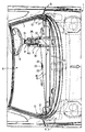
- The invention will be more apparent from the description of one embodiment thereof given hereinafter by non-limiting example with reference to the accompanying drawing, which represents a diagrammatic plan view of a vehicle provided with the device according to the invention.
- In said drawing, the reference numeral 1 indicates overall a vehicle, in this case a motor vehicle, the
structure 2 of which comprises a body, of which a pair ofopposing body sides 5 form part, and a steering column 4 disposed parallel to thebody sides 5. The pair ofbody sides 5 laterally bound a passenger compartment 6 of the vehicle 1, into which the steering column 4 projects by thatend 8 provided with asteering wheel 9. - According to the invention, the
body sides 5 and steering column are interconnected by adevice 10 arranged to limit the collapse of thestructure 2, particularly in the case of frontal impact of the vehicle 1 against an obstacle and/or other vehicle. - The
device 10 comprises a pair ofreinforcement plates inner surface 13 of arespective body side 5, and ametal cable 15 taut transversely to the passenger compartment 6 and rigidly connecting thereinforcement plates body sides 5 by welding using a high number of weld spots, this latter facility being made possible by the fact that there is no cross-member connecting thebody sides 5 together. According to a preferred embodiment of the invention thecable 15 is connected to thereinforcement plates device 10 can comprise tensioning means 20 of any known type indicated diagrammatically merely as a block on the drawing, and connected mechanically in series with thecable 15. Thecable 15 is inserted throughrespective fixing brackets 21 each rigid with arespective reinforcement plate ends 22 of thecable 15, this being preferably formed of wire strands. - According to the invention, the
cable 15 engages not only with thebrackets 21 but also engagesrespective fixing means 25 for and rigid with the steering column 4 by passing in the manner of a loop about this latter. Specifically, thefixing brackets 21 are disposed to the front of and in a position diametrically opposite the steering column fixing means 25, which comprise a pair ofpulleys 30 fixed in mutually opposite positions to the side of the steering column 4, and aU-piece 31 fixed to theend 8 of the steering column 4 between thepulleys 30 and the steering wheel and having its concavity facing thepulleys 30. - Consequently, in the device according to the invention the
cable 15 is arranged in such a manner as to define in plan view a closed annular figure comprising a firststraight branch 40 taut between thefixing brackets 21 for thereinforcement plates opposing body sides 5, and a second and a third branch indicated respectively by 41 and 42 which are mutually oblique, opposite and asymmetrical, and extending taut between thefixing brackets 21, through which thecable 15 slidingly passes, and thepulleys 30, about which thebranches 41 and 42 pass to form acommon volute 44, which passes about theU-piece 31 so as to embrace the steering column in such a manner as to stress thecable 15, in particular thebranch 40, should the steering column move towards the passenger compartment 6.
In use, should a frontal impact occur, thevehicle body 2 deforms such that thebody sides 5 tend to move apart from each other to an extent which becomes progressively more pronounced in progressing towards the passenger compartment 6, and substantially a maximum precisely at theplates device 10 this movement apart is totally prevented (or at least considerably limited) because thebranch 40 of the loop formed by thecable 15 opposes this movement and retains the body sides in position, while it itself becomes subjected to tensile stress with the result that the body sides can move only by the amount allowed by the elastic extension (or elastic-plastic if yield conditions are reached) of thecable 15, so totally limiting the collapse of the structure of the vehicle 1 while ensuring that at least part of the energy developed by the impact is absorbed, this being converted into deformation energy of thecable 15. - If this latter is arranged as shown in the described example, ie wound about the
steering column 5 as a loop, thecable 15 is also able to prevent, or at least limit, any rearward movement of the steering column 4 because the tensile stress induced in thebranch 40 by the attempted movement of thebody sides 5 results in tension in thebranches 41 and 42 in the direction of the arrows, with the result that an axial thrust is exerted on the steering column 4 in the direction of the arrow, ie in the opposite direction to that produced by the impact, even if this latter has not produced sufficient energy to produce for example the rearward movement of the vehicle engine-gearbox unit. In contrast, the thrust transmitted by the impact to the steering column 4 is also discharged to thecable 15 to produce in the branch 40 a stress which opposes the moving-apart of thebody sides 5. Thus, with the illustrated arrangement of thecable 15, the impact stresses on thebody sides 5 and steering column 4 are simultaneously discharged to thecable 15 and absorbed by the elastic deformation thereof, to limit or even prevent separation of thebody sides 5 from the cross-members forming the load-bearing framework of thevehicle body 2. Thecable 15 cannot become detached from thebody sides 5 because as the plates are connected only to a cable, ie to an element of very small bulk, they can be made suitably large and be fixed to thebody 2 by a large number of weld spots (or connection members), so ensuring that local stresses on them are absorbed. These stresses are in any case limited by the fact that thecable 15 is a very flexible element, so that it transmits only limited shear and torsional forces to thebody sides 5.
Claims (5)
- A device for limiting the collapse of a vehicle structure on impact, particularly on frontal impact, said structure comprising a pair of opposing body sides (5) forming part of the vehicle body and laterally bounding the vehicle passenger compartment, and a steering column (4) disposed parallel to the body sides, characterised by comprising a pair of reinforcement plates (11, 12), each of which is rigidly fixed against a respective inner surface (13) of a respective said body side, and a metal cable (15) extending taut transversely to the passenger compartment and rigidly connecting said reinforcement plates together.
- A device as claimed in claim 1, characterised in that said cable (15) is connected to said reinforcement plates (11, 12) in such a manner as to be pretensioned.
- A device as claimed in claim 1 or 2, characterised by comprising tensioning means (20) for said cable.
- A device as claimed in any one of the preceding claims, characterised in that said cable (15) is inserted through respective fixing brackets (21) each rigid with a respective reinforcement plate, and then engages respective fixing means for and rigid with said steering column; said fixing brackets (21) being disposed to the front of and in a position diametrically opposite said steering column fixing means (25).
- A device as claimed in claim 4, characterised in that said steering column fixing means comprise a pair of pulleys (30) fixed in mutually opposite positions to the side of said steering column, and a U-piece (31) fixed to a first end of said steering column between said pulleys and the column steering wheel; said cable (15) being arranged in such a manner as to define in plan view a closed annular figure comprising a first straight branch (40) extending taut between said fixing brackets for the reinforcement plates in such a manner as to connect together said opposing body sides, and a second and a third branch (41, 42) which are mutually oblique and opposite and extend taut between said fixing brackets and said pulleys, about which said second and third branch pass to form a common volute (44), which passes about said steering column U-piece.
Applications Claiming Priority (2)
| Application Number | Priority Date | Filing Date | Title |
|---|---|---|---|
| IT68149/88A IT1224028B (en) | 1988-12-23 | 1988-12-23 | DEVICE TO CONTAIN THE COLLAPSION OF THE VEHICLE STRUCTURE IN THE EVENT OF A FRONTAL IMPACT |
| IT6814988 | 1988-12-23 |
Publications (2)
| Publication Number | Publication Date |
|---|---|
| EP0374976A1 EP0374976A1 (en) | 1990-06-27 |
| EP0374976B1 true EP0374976B1 (en) | 1992-09-16 |
Family
ID=11308176
Family Applications (1)
| Application Number | Title | Priority Date | Filing Date |
|---|---|---|---|
| EP89124017A Expired EP0374976B1 (en) | 1988-12-23 | 1989-12-27 | Device for limiting the collapse of a vehicle structure on frontal impact |
Country Status (6)
| Country | Link |
|---|---|
| US (1) | US5039126A (en) |
| EP (1) | EP0374976B1 (en) |
| BR (1) | BR8906759A (en) |
| DE (1) | DE68902912T2 (en) |
| ES (1) | ES2035511T3 (en) |
| IT (1) | IT1224028B (en) |
Families Citing this family (6)
| Publication number | Priority date | Publication date | Assignee | Title |
|---|---|---|---|---|
| US5259646A (en) * | 1992-03-20 | 1993-11-09 | Nissan Research & Development, Inc. | Multifunction one-piece bracket to support a steering column assemby and brake pedal support bracket in an automobile |
| DE4230669C2 (en) * | 1992-09-14 | 1999-10-28 | Opel Adam Ag | Front structure of a motor vehicle |
| US5701645A (en) * | 1994-04-06 | 1997-12-30 | Motorola, Inc. | Acoustic wave device manufacturing method |
| WO1998040262A1 (en) * | 1997-03-10 | 1998-09-17 | Taexpa, S.A. | Impact damping system for vehicles |
| GB2578323A (en) | 2018-10-23 | 2020-05-06 | Ford Global Tech Llc | Powertrain mount assemblies |
| DE102019002469A1 (en) | 2019-04-03 | 2019-10-17 | Daimler Ag | Absorption element for a vehicle |
Family Cites Families (8)
| Publication number | Priority date | Publication date | Assignee | Title |
|---|---|---|---|---|
| US1959974A (en) * | 1932-12-12 | 1934-05-22 | Oscar L Westgate | Accessory for automobiles |
| US3011823A (en) * | 1959-05-08 | 1961-12-05 | William O Maher | Vehicle safety steering column and protective shield |
| FR1594234A (en) * | 1968-12-09 | 1970-06-01 | ||
| DE3337232A1 (en) * | 1983-10-13 | 1985-06-27 | Audi AG, 8070 Ingolstadt | DEVICE FOR USING THE IMPACT ENERGY OF A VEHICLE FOR A SAFETY DEVICE FOR PROTECTING THE VEHICLE occupants |
| DE3627558C1 (en) * | 1986-08-14 | 1987-12-17 | Audi Ag | Security system for motor vehicles |
| DE3642437C1 (en) * | 1986-12-12 | 1988-03-24 | Audi Ag | Steering column mount |
| DE3703021A1 (en) * | 1987-02-02 | 1988-08-11 | Sadler Norbert | Safety device in motor vehicles for protecting the occupants against lateral impacts |
| DE3710808A1 (en) * | 1987-03-31 | 1988-10-20 | Daimler Benz Ag | SUPPORT FOR ENERGY-ABSORBING DEFORMED BODY STRUCTURES ON AN ELASTICALLY BEARED FRONT ENGINE OF MOTOR VEHICLES |
-
1988
- 1988-12-23 IT IT68149/88A patent/IT1224028B/en active
-
1989
- 1989-12-21 US US07/452,741 patent/US5039126A/en not_active Expired - Fee Related
- 1989-12-21 BR BR898906759A patent/BR8906759A/en not_active Application Discontinuation
- 1989-12-27 EP EP89124017A patent/EP0374976B1/en not_active Expired
- 1989-12-27 ES ES198989124017T patent/ES2035511T3/en not_active Expired - Lifetime
- 1989-12-27 DE DE8989124017T patent/DE68902912T2/en not_active Expired - Fee Related
Also Published As
| Publication number | Publication date |
|---|---|
| BR8906759A (en) | 1990-09-18 |
| DE68902912D1 (en) | 1992-10-22 |
| EP0374976A1 (en) | 1990-06-27 |
| DE68902912T2 (en) | 1993-03-18 |
| IT8868149A0 (en) | 1988-12-23 |
| IT1224028B (en) | 1990-09-26 |
| US5039126A (en) | 1991-08-13 |
| ES2035511T3 (en) | 1993-04-16 |
Similar Documents
| Publication | Publication Date | Title |
|---|---|---|
| US6631942B1 (en) | Front body structure for vehicle | |
| US5517877A (en) | Collapsible steering column assembly | |
| US8070217B2 (en) | Vehicle body rear part structure | |
| JP3498614B2 (en) | Vehicle body structure | |
| US4840424A (en) | Automotive rear underbody structure | |
| JPH11171045A (en) | Impact absorbing body structure for vehicles | |
| US6676200B1 (en) | Automotive underbody with lateral energy absorption augmentation | |
| JP4691964B2 (en) | Vehicle front structure | |
| JP2022096590A (en) | Front vehicle body structure | |
| US5039126A (en) | Device for limiting the collapse of a vehicle structure on frontal impact | |
| US10618561B2 (en) | Vehicle front structure | |
| GB2203706A (en) | A roll-over yoke for a motor vehicle | |
| DE202018100260U1 (en) | vehicle frame | |
| US3990720A (en) | Upper coupler plate assembly | |
| US10814810B2 (en) | Bumper apparatus for vehicle | |
| US11679816B2 (en) | Vehicle body structure | |
| KR19980018339A (en) | Safety device for capover vehicle | |
| JP2001030954A (en) | Car body front structure | |
| CN108516015A (en) | Low-speed electronic automotive C column inner panel assembly and its welding procedure | |
| CN117203117A (en) | Instrument panel bracket for motor vehicles | |
| JP3294495B2 (en) | Elasto-plastic energy absorber | |
| JP3104732B2 (en) | Knee protector structure for vehicle | |
| JP2842107B2 (en) | Vehicle bumper mounting structure | |
| JP4014292B2 (en) | Front body structure of the vehicle | |
| KR100440287B1 (en) | join structure for a shiping hook of vehicle |
Legal Events
| Date | Code | Title | Description |
|---|---|---|---|
| PUAI | Public reference made under article 153(3) epc to a published international application that has entered the european phase |
Free format text: ORIGINAL CODE: 0009012 |
|
| AK | Designated contracting states |
Kind code of ref document: A1 Designated state(s): DE ES FR GB SE |
|
| 17P | Request for examination filed |
Effective date: 19901211 |
|
| 17Q | First examination report despatched |
Effective date: 19911114 |
|
| GRAA | (expected) grant |
Free format text: ORIGINAL CODE: 0009210 |
|
| AK | Designated contracting states |
Kind code of ref document: B1 Designated state(s): DE ES FR GB SE |
|
| REF | Corresponds to: |
Ref document number: 68902912 Country of ref document: DE Date of ref document: 19921022 |
|
| ET | Fr: translation filed | ||
| REG | Reference to a national code |
Ref country code: ES Ref legal event code: FG2A Ref document number: 2035511 Country of ref document: ES Kind code of ref document: T3 |
|
| PLBE | No opposition filed within time limit |
Free format text: ORIGINAL CODE: 0009261 |
|
| STAA | Information on the status of an ep patent application or granted ep patent |
Free format text: STATUS: NO OPPOSITION FILED WITHIN TIME LIMIT |
|
| 26N | No opposition filed | ||
| PGFP | Annual fee paid to national office [announced via postgrant information from national office to epo] |
Ref country code: ES Payment date: 19931122 Year of fee payment: 5 |
|
| PGFP | Annual fee paid to national office [announced via postgrant information from national office to epo] |
Ref country code: GB Payment date: 19931214 Year of fee payment: 5 |
|
| PG25 | Lapsed in a contracting state [announced via postgrant information from national office to epo] |
Ref country code: GB Effective date: 19941227 |
|
| PG25 | Lapsed in a contracting state [announced via postgrant information from national office to epo] |
Ref country code: ES Free format text: LAPSE BECAUSE OF THE APPLICANT RENOUNCES Effective date: 19941228 |
|
| EAL | Se: european patent in force in sweden |
Ref document number: 89124017.8 |
|
| GBPC | Gb: european patent ceased through non-payment of renewal fee |
Effective date: 19941227 |
|
| PGFP | Annual fee paid to national office [announced via postgrant information from national office to epo] |
Ref country code: SE Payment date: 19981119 Year of fee payment: 10 |
|
| PGFP | Annual fee paid to national office [announced via postgrant information from national office to epo] |
Ref country code: FR Payment date: 19991123 Year of fee payment: 11 |
|
| PG25 | Lapsed in a contracting state [announced via postgrant information from national office to epo] |
Ref country code: SE Free format text: LAPSE BECAUSE OF NON-PAYMENT OF DUE FEES Effective date: 19991228 |
|
| PGFP | Annual fee paid to national office [announced via postgrant information from national office to epo] |
Ref country code: DE Payment date: 20000211 Year of fee payment: 11 |
|
| EUG | Se: european patent has lapsed |
Ref document number: 89124017.8 |
|
| REG | Reference to a national code |
Ref country code: ES Ref legal event code: FD2A Effective date: 20010402 |
|
| PG25 | Lapsed in a contracting state [announced via postgrant information from national office to epo] |
Ref country code: FR Free format text: LAPSE BECAUSE OF NON-PAYMENT OF DUE FEES Effective date: 20010831 |
|
| REG | Reference to a national code |
Ref country code: FR Ref legal event code: ST |
|
| PG25 | Lapsed in a contracting state [announced via postgrant information from national office to epo] |
Ref country code: DE Free format text: LAPSE BECAUSE OF NON-PAYMENT OF DUE FEES Effective date: 20011002 |