EP0374584A1 - Method for operating a direct current generator connected to an internal-combustion engine as starter motor, and device therefor - Google Patents
Method for operating a direct current generator connected to an internal-combustion engine as starter motor, and device therefor Download PDFInfo
- Publication number
- EP0374584A1 EP0374584A1 EP89122473A EP89122473A EP0374584A1 EP 0374584 A1 EP0374584 A1 EP 0374584A1 EP 89122473 A EP89122473 A EP 89122473A EP 89122473 A EP89122473 A EP 89122473A EP 0374584 A1 EP0374584 A1 EP 0374584A1
- Authority
- EP
- European Patent Office
- Prior art keywords
- switch
- generator
- line
- current
- winding
- Prior art date
- Legal status (The legal status is an assumption and is not a legal conclusion. Google has not performed a legal analysis and makes no representation as to the accuracy of the status listed.)
- Granted
Links
Images


Classifications
-
- F—MECHANICAL ENGINEERING; LIGHTING; HEATING; WEAPONS; BLASTING
- F02—COMBUSTION ENGINES; HOT-GAS OR COMBUSTION-PRODUCT ENGINE PLANTS
- F02N—STARTING OF COMBUSTION ENGINES; STARTING AIDS FOR SUCH ENGINES, NOT OTHERWISE PROVIDED FOR
- F02N15/00—Other power-operated starting apparatus; Component parts, details, or accessories, not provided for in, or of interest apart from groups F02N5/00 - F02N13/00
-
- F—MECHANICAL ENGINEERING; LIGHTING; HEATING; WEAPONS; BLASTING
- F02—COMBUSTION ENGINES; HOT-GAS OR COMBUSTION-PRODUCT ENGINE PLANTS
- F02N—STARTING OF COMBUSTION ENGINES; STARTING AIDS FOR SUCH ENGINES, NOT OTHERWISE PROVIDED FOR
- F02N11/00—Starting of engines by means of electric motors
- F02N11/04—Starting of engines by means of electric motors the motors being associated with current generators
Landscapes
- Engineering & Computer Science (AREA)
- Chemical & Material Sciences (AREA)
- Combustion & Propulsion (AREA)
- Mechanical Engineering (AREA)
- General Engineering & Computer Science (AREA)
- Control Of Eletrric Generators (AREA)
- Motor And Converter Starters (AREA)
- Control Of Throttle Valves Provided In The Intake System Or In The Exhaust System (AREA)
- Electrical Control Of Air Or Fuel Supplied To Internal-Combustion Engine (AREA)
- Valve Device For Special Equipments (AREA)
- Synchronous Machinery (AREA)
Abstract
Description
Die Erfindung betrifft ein Verfahren zum Betreiben eines an eine Brennkraftmaschine angeschlossenen Gleichstrom-Nebenschluß-Generators als Anlasser und eine Vorrichtung dafür.The invention relates to a method for operating a direct current shunt generator connected to an internal combustion engine as a starter and a device therefor.
Zum Anlassen von Brennkraftmaschinen wird üblicherweise ein spezieller elektrischer Anlaßmotor eingesetzt, der von einer Starterbatterie gespeist wird und über ein Ritzel die mit einem Zahnkranz versehene Schwungscheibe der Brennkraftmaschine in Drehung versetzt. Bei Brennkraftmaschinen, die einen starken elektrischen Generator betreiben, der einen elektrischen Antriebsmotor speist, ist es bekannt, den Anlaßvorgang über den Generator vorzunehmen, d.h. den Generator als Anlasser zu verwenden, damit der spezielle Anlaßmotor und der Zahnkranz eingespart werden können. Zu diesem Zweck wird der Generator mit einer besonderen Hilfswicklung versehen. Ein derartiges Verfahren bzw. eine derartige Anordnung ist in dem Buch "Elektrische Triebfahrzeuge", Band 2, Seite 645, von K. Sachs beschrieben, wobei Fahrzeuge mit dieselelektrischem Antrieb betroffen sind. Die Hilfswicklungen sind in ihrer Dimensionierung an die Starterbatterie angepaßt. Wird zum Anlassen ein Generator ohne Hilfswicklung verwendet und die Erregerwicklung gleichzeitig mit der Ankerwicklung auf die Starterbatterie geschaltet, so sinkt die Spannung der Starterbatterie während des Einschaltvorganges stark ab und der Generator wird nur schwach erregt. Als Folge davon wird das vom Generator abgegebene Drehmoment, das proportional der Erregung (dem magnetischen Fluß) und dem Ankerstrom ist, zu gering, um den Dieselmotor zu starten.For starting internal combustion engines, a special electric starter motor is usually used, which is fed by a starter battery and rotates the flywheel of the internal combustion engine, which is provided with a ring gear, by means of a pinion. In internal combustion engines that operate a powerful electric generator that feeds an electric drive motor, it is known to carry out the starting process via the generator, ie to use the generator as a starter, so that the special starter motor and the ring gear can be saved. For this purpose, the generator is provided with a special auxiliary winding. Such a method or such an arrangement is described in the book "Electric Power Vehicles",
Der Erfindung liegt die Aufgabe zugrunde, ein kostengünstiges Verfahren und eine dafür geeignete Vorrichtung für das Betreiben eines an eine Brennkraftmaschine angeschlossenen Gleichstrom-Nebenschluß-Generators als Anlasser zu schaffen, bei dem keine Hilfswicklungen nötig sind.The invention has for its object to provide an inexpensive method and a suitable device for operating a DC shunt generator connected to an internal combustion engine as a starter, in which no auxiliary windings are necessary.
Diese Aufgabe wird erfindungsgemäß dadurch gelöst, daß die Erregerwicklung zeitlich vor der Ankerwicklung von Strom durchflossen wird. Es kann sich daher zunächst ein starkes Erregerfeld aufbauen, so daß, sobald zeitverzögert die Ankerwicklung von Strom durchflossen wird, eine genügend große Erregung vorhanden ist, um ein ausreichendes Drehmoment zu erzeugen. Es ist dabei vorteilhaft, wenn die Ankerwicklung erst nach Ablauf einer der doppelten Zeitkonstante der Erregerwicklung entsprechenden Zeit von Strom durchflossen wird, weil dann über 85 % der möglichen Erregung erreicht wird. Diese Zeit zum Aufbau des Erregerfeldes kann ungefähr 0,5 bis 1 sec. betragen, nachdem der Anlaßvorgang durch Betätigen eines Zündschlüssels eingeleitet wurde.This object is achieved in that the excitation winding is flowed through by current before the armature winding. A strong field of excitation can therefore initially build up, so that as soon as current flows through the armature winding with a time delay, there is sufficient excitation to generate sufficient torque. It is advantageous if current flows through the armature winding only after a time corresponding to twice the time constant of the excitation winding, because then over 85% of the possible excitation is reached. This time to build up the excitation field can be approximately 0.5 to 1 sec. After the starting process has been initiated by actuating an ignition key.
Um den Ohm'schen Widerstand im Ankerkreis gering zu halten, kann gemäß einem weiteren Schritt der Erfindung die Wendepolwicklung beim Anlaßvorgang abgeschaltet werden.In order to keep the ohmic resistance in the armature circuit low, according to a further step of the invention, the reversing pole winding can be switched off during the starting process.
Erfindungsgemäß wird das beschriebene Verfahren durch eine Schaltungsanordnung erreicht, bei der in einer die Ankerwicklung mit einer Spannungsquelle verbindenden Leitung ein Schalter angeordnet ist, der mit einem Zeitglied in Wirkverbindung steht. Der Schalter verbindet Spannungsquelle und Ankerwicklung zeitverzögert, während die Erregerwicklung sofort mit der Spannungsquelle verbunden wird, so daß sich ungestört ein Erregerfeld aufbauen kann. Als Spannungsquelle findet eine Starterbatterie Verwendung, die stark genug ist, um problemlos die Erregerwicklung zu speisen und ein Erregerfeld zu erzeugen und anschließend einen ausreichenden Ankerstrom zur Verfügung stellt. Erst nachdem das Erregerfeld aufgebaut ist, schließt der Schalter und die Ankerwicklung wird von Strom durchflossen, woraufhin ein Drehmoment erzeugt und der Rotor des Generators und die Kurbelwelle der daran angeschlossenen Brennkraftmaschine in Drehung versetzt wird. Das Erregerfeld wird dabei nur geringfügig geschwächt.According to the invention, the method described is achieved by a circuit arrangement in which a switch is arranged in a line connecting the armature winding to a voltage source, which switch is operatively connected to a timing element. The switch connects the voltage source and armature winding with a time delay, while the excitation winding is immediately connected to the voltage source, so that an excitation field can build up undisturbed. A starter battery is used as the voltage source, which is strong enough to easily feed the excitation winding and generate an excitation field and then provide a sufficient armature current. Only after the field of excitation has been set up does the switch close and current flows through the armature winding, whereupon a torque is generated and the rotor of the generator and the crankshaft of the internal combustion engine connected to it are set in rotation. The field of excitation is only slightly weakened.
In einer vorteilhaften Weiterbildung des Erfindungsgegenstands ist der Schalter mit einem Schaltschütz verbunden und das Zeitglied in einer mit dem Schaltschütz in Verbindung stehenden Signalleitung angeordnet, die während des Anlaßvorgangs an die Spannungsquelle angeschlossen ist. Dadurch kann eine Steuerstromschaltung gebildet werden, die während des Anlaßvorgangs den Generator steuert, und schaltungstechnisch von einer Hauptstromschaltung getrennt ist, die während der Stromerzeugung des Generators wirksam ist.In an advantageous development of the subject matter of the invention, the switch is connected to a contactor and the timer is arranged in a signal line connected to the contactor, which is connected to the voltage source during the starting process. As a result, a control current circuit can be formed which controls the generator during the starting process and is separated in terms of circuitry from a main current circuit which is active during the current generation of the generator.
Wenn in der Signalleitung ein von einem Relais gesteuerter Schalter angeordnet ist, der in Abhängigkeit von der Fließrichtung des Stroms schaltbar ist, kann, sobald die Brennkraftmaschine angesprungen ist und selbständig läuft, so daß eine angeschlossene Lichtmaschine nunmehr Strom erzeugt, die Ankerwicklung des Generators automatisch von der Starterbatterie getrennt werden. Dazu ist es zweckmäßig, das Relais an einen Lichtmaschinenregler anzuschließen, wie er aus der Kfz-Technik bekannt ist.If a switch controlled by a relay is arranged in the signal line and can be switched as a function of the direction of flow of the current, as soon as the internal combustion engine has started and runs independently, so that a connected alternator now generates electricity, the armature winding of the generator is automatically switched off the starter battery. For this purpose, it is expedient to connect the relay to an alternator regulator, as is known from automotive engineering.
Eine weitere günstige Ausbildung des Erfindungsgegenstands, bei der der Generator mit einem elektrischen Antriebsmotor in Verbindung steht und diesen im Normalbetrieb speist, sieht vor, in einer den Generator mit dein Antriebsmotor verbindenden Leitung einen Schalter anzuordnen, der während des Anlaßvorgangs die Leitung unterbricht. Dadurch fließt kein Strom ab zum Antriebsmotor, so daß der Strom der Starterbatterie ausschließlich dem als Anlasser fungierenden Generator zur Verfügung steht.Another favorable embodiment of the subject matter of the invention, in which the generator is connected to an electric drive motor and feeds it in normal operation, provides for a switch to be arranged in a line connecting the generator to the drive motor, which switch interrupts the line during the starting process. As a result, no current flows to the drive motor, so that the current from the starter battery is only available to the generator acting as a starter.
Besonders vorteilhaft ist die Verwendung des beschriebenen Verfahrens und einer zugehörigen Schaltungsanordnung für ein Flurförderzeug, insbesondere Gabelstapler, mit einem oder mehreren elektrischen Antriebsmotoren, die ihre Stromversorgung aus einem von einer Brennkraftmaschine getriebenen Generator erhalten.It is particularly advantageous to use the described method and an associated circuit arrangement for an industrial truck, in particular forklift truck, with one or more electric drive motors which receive their power supply from a generator driven by an internal combustion engine.
Anhand der nachstehenden schematischen Figurenbeispiele soll die Erfindung näher erläutert werden.The invention will be explained in more detail with the aid of the following schematic examples of figures.
Es zeigen:
Figur 1 ein Diagramm mit dem zeitabhängigen Verlauf von Anker- und Erregerstrom,Figur 2 eine Hauptstromschaltung,Figur 3 eine Steuerschaltung zur Verwendung des Generators als Anlasser.
- FIG. 1 shows a diagram with the time-dependent course of armature and excitation current,
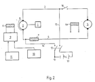
- FIG. 2 shows a main current circuit,
- Figure 3 shows a control circuit for using the generator as a starter.
In dein Diagramm in Figur 1 ist auf der Abszisse die Zeit aufgetragen und auf der Ordinate die Spannung der Starterbatterie in Prozent und der die Erregerwicklung und die Ankerwicklung durchfließende Strom in Prozent. Die mit A bezeichnete Kurve zeigt den Spannungsverlauf einer Starterbatterie. Die mit B bezeichnete Kurve stellt den Verlauf des die Ankerwicklung durchfließenden Stroms dar. Mit C ist der Verlauf des die Erregerwicklung durchfließenden Stroms gekennzeichnet. Die gestrichelte Linie D zeigt das beständige Ansteigen des Erregerstroms bei konstanter Batteriespannung.In your diagram in FIG. 1, the time is plotted on the abscissa and the voltage of the starter battery in percent and the current flowing through the excitation winding and the armature winding in percent on the ordinate. The curve labeled A shows the voltage profile of a starter battery. The curve labeled B represents the course of the current flowing through the armature winding. C denotes the course of the current flowing through the field winding. The dashed line D shows the constant rise in the excitation current with constant battery voltage.
Die Batteriespannung betrage zu Beginn des Startvorgangs 100 %. Der Beginn des Startvorgangs ist auf der Abszisse mit 0 gekennzeichnet. Wenn nun gleichzeitig ein Strom durch die Erregerwicklung und durch die Ankerwicklung fließt, so steigt der Stromfluß in der Ankerwicklung sehr schnell an. Eine ausreichende Drehbewegung kann jedoch noch nicht ereugt werden, weil das Erregerfeld noch nicht aufgebaut ist. Infolge der hohen Stromaufnahme bei gleichzeitiger Versorgung von Erreger- und Ankerwicklung bricht die Batteriespannung zuammen und fällt ab z.B. auf ca. 50 %. Als Folge davon steigt der Erregerstrom nur sehr langsam und fällt der Ankerstrom wieder ab. Zwar steigt die Batteriespannung ebenfalls wieder langsam an, ohne jedoch das ursprüngliche Niveau wieder zu erreichen. Auch der Erregerstrom und damit das Erregerfeld erreichen bei weitem nicht ihr Maximum. Infolge mangelnder Erregung bleibt daher auch das am Anker abgegebene Drehmoment klein.The battery voltage is 100% at the start of the start. The start of the start process is marked with 0 on the abscissa. If a current flows through the excitation winding and through the armature winding at the same time, the current flow in the armature winding increases very quickly. However, sufficient rotation cannot be demonstrated because the field of the exciter has not yet been built up. As a result of the high current consumption with simultaneous supply of excitation and armature windings, the battery voltage breaks down and drops, for example, to approx. 50%. As As a result, the excitation current increases very slowly and the armature current drops again. The battery voltage also slowly increases again, but without reaching the original level again. The excitation current and thus the excitation field are far from reaching their maximum. As a result of a lack of excitation, the torque delivered at the armature therefore remains small.
Die gestrichelte Linie D zeigt den Anstieg des Erregerstroms für den Fall konstanter Batteriespannung, der nur bei sehr großer Batteriekapazität erreicht wird, nicht aber bei einer Starterbatterie, wie sie für den üblicherweise zum Einsatz kommenden Anlaßmotor verwendet wird. Die Starterbatterie ist für einen Anlaßmotor ausreichend bemessen, weil der Anlaßmotor über ein Ritzel auf ein gezahntes Schwungrad der Kurbelwelle der Brennkraftmaschine einwirkt und wegen des großen Übersetzungsverhältnisses eine entsprechende Vergrößerung des Drehmoments erfolgt. Wird eine derartige Starterbatterie zur Speisung eines als Anlasser zweckentfremdeten Generators verwendet, der keine Hilfswicklungen aufweist, so bricht, wie geschildert, die Batteriespannung zusammen.The dashed line D shows the increase in the excitation current in the case of constant battery voltage, which is only achieved with a very large battery capacity, but not with a starter battery, as is used for the starter motor normally used. The starter battery is sufficiently dimensioned for a starter motor because the starter motor acts on a toothed flywheel of the crankshaft of the internal combustion engine via a pinion and because of the large transmission ratio, the torque is increased accordingly. If such a starter battery is used to supply a generator that is not used as a starter and has no auxiliary windings, the battery voltage breaks down, as described.
Dieses Problem wird gelöst, indem der Erregerstrom zeitlich vor dem Ankerstrom fließt gemäß Kurve E. Zum Zeitpunkt 0, also beim Beginn des Anlaßvorgangs, können dann z.B. bereits über 85 % des Erregerstroms fließen, so daß das Erregerfeld entsprechend aufgebaut ist, wenn der Strom die Ankerwicklung durchfließt. Es wird dann zwar der Erregerstrom wieder abfallen, was in dem Diagramm nicht dargestellt ist, aber da das Erregerfeld im Zeitpunkt der Freigabe des Ankerstroms bereits steht und eine gewisse Trägheit aufweist, kann sofort ein ausreichendes Drehmoment am Anker abgegeben werden.This problem is solved by the excitation current flowing in time before the armature current according to curve E. At
Figur 2 zeigt eine Brennkraftmaschine 1, die mit einem Generator 2 gekoppelt ist, der über Leitungen 3 und 4 mit einem elektrischen Antriebsmotor 5 in Verbindung steht und bei laufender Brennkraftmaschine 1 diesen mit Strom versorgt. Der Generator 2 ist mit einer Erregerwicklung 6, einer Wendepolwicklung 7 und einer Ankerwicklung 8 versehen. Der Motor 5 weist eine Erregerwicklung 6a auf. Die Erregerwicklung 6 des Generators 2 wird über eine Endstufe 9 mit Strom versorgt. Die Ansteuerung der Endstufe 9 geschieht während des Anlaßvorgangs über eine Startsteuerung 10 und während des Generatorbetriebs über eine Antriebssteuerung 11. Durch einen in diesem Beispiel als Doppelschalter ausgebildeten Schalter 12 ist eine Starterbatterie 13 über Leitungen 14 und 15 mit den Leitungen 3 und 4 verbindbar. In der Leitung 3 ist ein Schalter 16 vorgesehen, damit der Antriebsmotor 5 vom Generator 2 getrennt werden kann.FIG. 2 shows an
Figur 3 zeigt den Prinzipaufbau der Antriebssteuerung 11. An die Starterbatterie 13 ist über Leitungen 17 und 18 und eine Signalleitung 19 ein Schaltschütz 20 angeschlossen, das die Ankerwicklung 8 bei Bedarf über den Schalter 12 mit Strom versorgt, also den Generator einschaltet. Ein Zeitglied 21 ist in Reihe zu dem Schaltschütz 20 angeordnet. Ebenfalls in Reihe zu dem Schaltschütz 20 ist in der Signalleitung 19 ein Schalter 22 vorgesehen, der von eiem Relais 23 angesteuert wird, das sich in einer einen Lichtmaschinenregler 24 mit der Leitung 17 verbindenden Leitung 24a befindet. Der Lichtmaschinenregler 24 ist über eine Lichtmaschine 25, die zum Laden der Starterbatterie 13 und Versorgung des Lichtnetzes vorgesehen ist, und über eine Leitung 24b getrennt von Leitung 24a nochmals mit der Leitung 17 verbunden und über eine Leitung 24c mit der Leitung 18. In der Leitung 24a ist ein Schalter 26 angeordnet, der von einem Relais 27 angesteuert wird, das in eine Leitung 19a geschaltet ist. Die Leitung 19a ist an die Leitung 18 angeschlossen und über eine Leitung 17a mit der Leitung 17 verbunden und damit parallel zur Leitung 19 geschaltet. Ebenfalls an die Leitungen 17a und 18 angeschlossen und damit parallel geschaltet zu den Leitungen 19 und 19a ist eine Leitung 19b, in der sich ein Schaltschütz 28 befindet, das die Erregerwicklung 6 über einen Schalter 28a über die Endstufe 9 mit Strom versorgt. Desweiteren ist eine Leitung 19c an die Leitung 18 angeschlossen und über eine Leitung 17b an die Leitung 17 angeschlossen, also parallel geschaltet zu den Leitungen 19, 19a und 19b. In der Leitung 19c ist ein Schaltschütz 29 angeordnet, das mit dem Schalter 16 in Verbindung steht. Die bisher beschriebenen Schalter, Schaltschütze und Relais sind in Normalstellung geöffnet, das heißt sie unterbrechen die jeweilige Leitung.FIG. 3 shows the basic structure of the
Die Leitungen 17a und 18 sind schließlich noch durch eine Leitung 19d verbunden, die parallel geschaltet ist zu den Leitungen 19a bis c. In der Leitung 19d ist ein Relais 30 vorgesehen, das einen Schalter 31 steuert, der in der Leitung 19c in Reihe zu dem Schaltschütz 29 angeordnet ist. Der Schalter 31 ist in Normalstellung, d.h. wenn das Schaltschütz 29 stromlos ist, geschlossen, die Leitung 19c also nicht unterbrochen.The
Die Leitungen 17a und 17b sind über einen Anlaßschalter 32 miteinander und mit der Leitung 17 verbindbar. Der Anlaßschalter 32 hat drei Stellungen. Die erste Stellung I ist die Ruhestellung, in der die Leitungen 17a und 17b nicht mit der Leitung 17 verbunden sind und somit kein Strom fließt. In der zweiten Stellung II ist die Leitung 17 mit der Leitung 17b verbunden, wodurch diese an die Starterbatterie 13 angeschlossen ist. Die dritte Stellung III des Schalters 32 verbindet die Leitung 17 gleichzeitig mit den Leitungen 17a und 17b und setzt sie damit unter Strom. Die Stellungen I und II sind Dauerstellungen. Stellung III muß während des Anlaßvorgangs festgehalten werden. Beim Loslassen des Schalters 32 springt dieser selbstätig in Stellung II zurück.The
Beim Anlassen wird der Schalter 32 in die Stellung III gedrückt. Dadurch werden die Relais 27 und 30 angesteuert, was ein Schließen des Schalters 26 und ein Öffnen des Schalters 31 bewirkt. Der Schalter 31 trennt damit die Leitung 17b, so daß das Schaltschütz 29 stromlos bleibt und der Schalter 16 die Leitung 3 zwischen Generator 2 und elektrischem Antriebsmotor 5 unterbricht.When starting the
Weiter wird das Schaltschütz 28 unverzögert eingeschaltet, damit Strom zur Erregerwicklung 6 fließen kann.Furthermore, the
Das Schließen des Schalters 26 bewirkt, daß über das Relais 23 und den Schalter 22 das Schaltschütz 20 und das Zeitglied 21 an Spannung gelegt werden. Das Schaltschütz 20 schaltet daher zeitverzögert den Generator 2 bzw. dessen Ankerwicklung 8 auf die Starterbatterie 13, so daß ein Drehmoment erzeugt wird, das die Kurbelwelle der Brennkraftmaschine 1 in Drehung versetzt, bis diese anspringt und hochläuft. Wenn die Brennkraftmaschine 1 selbsttätig läuft, gibt die Lichtmaschine 25 Spannung ab, so daß sich die Fließrichtung des Stroms in der Leitung 24a umkehrt und das Relais 23, das abhängig von der Fließrichtung schaltet, den Schalter 22 in der Signalleitung 19 öffnet. Daraufhin ist das Schaltschütz 20 stromlos, wodurch der Schalter 12 öffnet und der Generator 2 wieder von der Starterbatterie 13 getrennt wird.Closing the switch 26 causes the contactor 20 and the
Beim anschließenden Loslassen des Schalters 32 springt dieser selbsttätig in die Stellung II zurück, wodurch das Relais 27 stromlos ist und der Schalter 26 öffnet. Das Schaltschütz 28 wird ebenfalls von der Starterbatterie 13 getrennt, so daß kein Strom mehr von der Starterbatterie 13 aus in die Erregerwicklung 6 fließt. Der Erregerstrom wird nunmehr von der Lichtmaschine 25 selbst erzeugt und von der Antriebssteuerung 11 kontrolliert. Schließlich ist auch das Relais 30 stromlos, was ein Schließen des Schalters 31 und daraufhin ein Anziehen des Schaltschützes 29 bewirkt, so daß der Schalter 16 die unterbrochene Leitung 3 wieder verbindet und der Generatorstrom zum elektrischen Antriebsmotor 5 fließen kann.When
Claims (9)
Priority Applications (1)
| Application Number | Priority Date | Filing Date | Title |
|---|---|---|---|
| AT89122473T ATE74405T1 (en) | 1988-12-20 | 1989-12-06 | METHOD OF OPERATING A SHUNT D.C. GENERATOR CONNECTED TO AN ENGINE AS A STARTING MOTOR AND DEVICE THEREOF. |
Applications Claiming Priority (2)
| Application Number | Priority Date | Filing Date | Title |
|---|---|---|---|
| DE3842834 | 1988-12-20 | ||
| DE3842834A DE3842834A1 (en) | 1988-12-20 | 1988-12-20 | METHOD FOR OPERATING A DC-CIRCUIT GENERATOR CONNECTED TO AN INTERNAL COMBUSTION ENGINE AS A STARTER AND DEVICE THEREFOR |
Publications (2)
| Publication Number | Publication Date |
|---|---|
| EP0374584A1 true EP0374584A1 (en) | 1990-06-27 |
| EP0374584B1 EP0374584B1 (en) | 1992-04-01 |
Family
ID=6369601
Family Applications (1)
| Application Number | Title | Priority Date | Filing Date |
|---|---|---|---|
| EP89122473A Expired - Lifetime EP0374584B1 (en) | 1988-12-20 | 1989-12-06 | Method for operating a direct current generator connected to an internal-combustion engine as starter motor, and device therefor |
Country Status (9)
| Country | Link |
|---|---|
| EP (1) | EP0374584B1 (en) |
| JP (1) | JPH02246799A (en) |
| KR (1) | KR900010220A (en) |
| AT (1) | ATE74405T1 (en) |
| BG (1) | BG50506A3 (en) |
| DE (2) | DE3842834A1 (en) |
| DK (1) | DK168171B1 (en) |
| ES (1) | ES2031678T3 (en) |
| GR (1) | GR3004703T3 (en) |
Cited By (1)
| Publication number | Priority date | Publication date | Assignee | Title |
|---|---|---|---|---|
| US5495127A (en) * | 1993-09-02 | 1996-02-27 | Nippondenso Co., Ltd. | Engine starting apparatus for vehicles |
Families Citing this family (1)
| Publication number | Priority date | Publication date | Assignee | Title |
|---|---|---|---|---|
| JP2012228017A (en) * | 2011-04-18 | 2012-11-15 | Mitsubishi Electric Corp | Controller of generator-motor |
Citations (2)
| Publication number | Priority date | Publication date | Assignee | Title |
|---|---|---|---|---|
| FR518235A (en) * | 1916-01-29 | 1921-05-21 | Siemens Schuckertwerke Gmbh | Starting system for direct current shunt motors |
| US3175095A (en) * | 1960-02-10 | 1965-03-23 | Bendix Corp | Outboard marine starter-generator dynamo |
Family Cites Families (2)
| Publication number | Priority date | Publication date | Assignee | Title |
|---|---|---|---|---|
| JPS5577381A (en) * | 1978-12-04 | 1980-06-11 | Toyo Umpanki Co Ltd | Starter for shunt-wound dc motor |
| JP2617936B2 (en) * | 1987-05-09 | 1997-06-11 | 三菱電機株式会社 | Engine start charging device |
-
1988
- 1988-12-20 DE DE3842834A patent/DE3842834A1/en not_active Withdrawn
-
1989
- 1989-12-06 AT AT89122473T patent/ATE74405T1/en not_active IP Right Cessation
- 1989-12-06 ES ES198989122473T patent/ES2031678T3/en not_active Expired - Lifetime
- 1989-12-06 DE DE8989122473T patent/DE58901089D1/en not_active Expired - Fee Related
- 1989-12-06 EP EP89122473A patent/EP0374584B1/en not_active Expired - Lifetime
- 1989-12-18 BG BG90677A patent/BG50506A3/en unknown
- 1989-12-19 DK DK647589A patent/DK168171B1/en not_active IP Right Cessation
- 1989-12-20 JP JP1328542A patent/JPH02246799A/en active Pending
- 1989-12-20 KR KR1019890018991A patent/KR900010220A/en not_active Application Discontinuation
-
1992
- 1992-05-26 GR GR920401038T patent/GR3004703T3/el unknown
Patent Citations (2)
| Publication number | Priority date | Publication date | Assignee | Title |
|---|---|---|---|---|
| FR518235A (en) * | 1916-01-29 | 1921-05-21 | Siemens Schuckertwerke Gmbh | Starting system for direct current shunt motors |
| US3175095A (en) * | 1960-02-10 | 1965-03-23 | Bendix Corp | Outboard marine starter-generator dynamo |
Cited By (1)
| Publication number | Priority date | Publication date | Assignee | Title |
|---|---|---|---|---|
| US5495127A (en) * | 1993-09-02 | 1996-02-27 | Nippondenso Co., Ltd. | Engine starting apparatus for vehicles |
Also Published As
| Publication number | Publication date |
|---|---|
| JPH02246799A (en) | 1990-10-02 |
| GR3004703T3 (en) | 1993-04-28 |
| DK647589D0 (en) | 1989-12-19 |
| EP0374584B1 (en) | 1992-04-01 |
| DK647589A (en) | 1990-06-21 |
| ATE74405T1 (en) | 1992-04-15 |
| KR900010220A (en) | 1990-07-06 |
| DE3842834A1 (en) | 1990-06-21 |
| ES2031678T3 (en) | 1992-12-16 |
| DK168171B1 (en) | 1994-02-21 |
| BG50506A3 (en) | 1992-08-14 |
| DE58901089D1 (en) | 1992-05-07 |
Similar Documents
| Publication | Publication Date | Title |
|---|---|---|
| DE2839468C2 (en) | ||
| DE4302809B4 (en) | Method for regulating or controlling the vehicle electrical system voltage in motor vehicles and device for carrying out the method | |
| DE102006006841B4 (en) | Control of the restart of an internal combustion engine | |
| EP2297450A1 (en) | Starter for an internal combustion engine | |
| DE102005038746A1 (en) | Voltage supplying method for use in multi-voltage vehicle electrical system, involves arranging batteries in switching configuration such that supply voltage is provided for generator, and making switching from one to other configuration | |
| DE3130704A1 (en) | "HYDRAULIC PUMP DRIVE SYSTEM FOR A MOTOR VEHICLE" | |
| DE2153655C2 (en) | Power supply device for a motor vehicle | |
| EP0406340B1 (en) | Battery-charging device | |
| EP0374584B1 (en) | Method for operating a direct current generator connected to an internal-combustion engine as starter motor, and device therefor | |
| DE3819219A1 (en) | TURNING DEVICE FOR INTERNAL COMBUSTION ENGINES | |
| DE10260621B4 (en) | Starting device for cranking an internal combustion engine | |
| DE2225376A1 (en) | ||
| DE632584C (en) | Electric starting device for internal combustion engines | |
| DE2413565B2 (en) | Circuit arrangement for starting a vehicle engine by means of a starter motor | |
| DE661807C (en) | Circuit arrangement for internal combustion-electric vehicle drive | |
| DE915601C (en) | Method for starting welding units with internal combustion engine drive | |
| DE10250488A1 (en) | Supply arrangement for motor vehicle has battery isolated from on-board electrical system at least during energy storage device charging and consumption of stored energy by electrical system loads | |
| DE246262C (en) | ||
| DE379423C (en) | Automatic electrical generating system | |
| EP4047201A1 (en) | Starting voltage module for a starter system of a combustion engine | |
| DE496994C (en) | Electrodynamic braking of direct current vehicle electric motors, which are started and regulated by a rotating voltage divider | |
| DE848669C (en) | Arrangement for regenerative braking of DC main circuit motors with auxiliary excitation windings that can be connected to the contact line and are shunted to the series windings and armatures of the motors | |
| DE321008C (en) | Electric starting device for internal combustion engines, especially for vehicles | |
| DE10338159A1 (en) | Voltage supply device for a motor vehicle has generator periodically connected to a drive unit on the drive side of the motor vehicle coupling from the combustion engine | |
| AT215549B (en) | Switching arrangement for the automatic start-up and shutdown of a power generator |
Legal Events
| Date | Code | Title | Description |
|---|---|---|---|
| PUAI | Public reference made under article 153(3) epc to a published international application that has entered the european phase |
Free format text: ORIGINAL CODE: 0009012 |
|
| 17P | Request for examination filed |
Effective date: 19900331 |
|
| AK | Designated contracting states |
Kind code of ref document: A1 Designated state(s): AT BE CH DE ES FR GB GR IT LI NL SE |
|
| 17Q | First examination report despatched |
Effective date: 19910125 |
|
| ITF | It: translation for a ep patent filed |
Owner name: DE DOMINICIS & MAYER S.R.L. |
|
| GRAA | (expected) grant |
Free format text: ORIGINAL CODE: 0009210 |
|
| AK | Designated contracting states |
Kind code of ref document: B1 Designated state(s): AT BE CH DE ES FR GB GR IT LI NL SE |
|
| REF | Corresponds to: |
Ref document number: 74405 Country of ref document: AT Date of ref document: 19920415 Kind code of ref document: T |
|
| REF | Corresponds to: |
Ref document number: 58901089 Country of ref document: DE Date of ref document: 19920507 |
|
| GBT | Gb: translation of ep patent filed (gb section 77(6)(a)/1977) | ||
| ET | Fr: translation filed | ||
| REG | Reference to a national code |
Ref country code: ES Ref legal event code: FG2A Ref document number: 2031678 Country of ref document: ES Kind code of ref document: T3 |
|
| REG | Reference to a national code |
Ref country code: GR Ref legal event code: FG4A Free format text: 3004703 |
|
| PLBE | No opposition filed within time limit |
Free format text: ORIGINAL CODE: 0009261 |
|
| STAA | Information on the status of an ep patent application or granted ep patent |
Free format text: STATUS: NO OPPOSITION FILED WITHIN TIME LIMIT |
|
| 26N | No opposition filed | ||
| PGFP | Annual fee paid to national office [announced via postgrant information from national office to epo] |
Ref country code: AT Payment date: 19941213 Year of fee payment: 6 |
|
| PGFP | Annual fee paid to national office [announced via postgrant information from national office to epo] |
Ref country code: CH Payment date: 19941214 Year of fee payment: 6 |
|
| PGFP | Annual fee paid to national office [announced via postgrant information from national office to epo] |
Ref country code: GR Payment date: 19941220 Year of fee payment: 6 |
|
| PGFP | Annual fee paid to national office [announced via postgrant information from national office to epo] |
Ref country code: ES Payment date: 19941223 Year of fee payment: 6 |
|
| PGFP | Annual fee paid to national office [announced via postgrant information from national office to epo] |
Ref country code: NL Payment date: 19941231 Year of fee payment: 6 |
|
| EAL | Se: european patent in force in sweden |
Ref document number: 89122473.5 |
|
| PGFP | Annual fee paid to national office [announced via postgrant information from national office to epo] |
Ref country code: BE Payment date: 19950207 Year of fee payment: 6 |
|
| PG25 | Lapsed in a contracting state [announced via postgrant information from national office to epo] |
Ref country code: AT Effective date: 19951206 |
|
| PG25 | Lapsed in a contracting state [announced via postgrant information from national office to epo] |
Ref country code: ES Free format text: LAPSE BECAUSE OF THE APPLICANT RENOUNCES Effective date: 19951207 |
|
| PG25 | Lapsed in a contracting state [announced via postgrant information from national office to epo] |
Ref country code: LI Effective date: 19951231 Ref country code: CH Effective date: 19951231 Ref country code: BE Effective date: 19951231 |
|
| BERE | Be: lapsed |
Owner name: STILL G.M.B.H. Effective date: 19951231 |
|
| PG25 | Lapsed in a contracting state [announced via postgrant information from national office to epo] |
Ref country code: GR Free format text: THE PATENT HAS BEEN ANNULLED BY A DECISION OF A NATIONAL AUTHORITY Effective date: 19960630 |
|
| PG25 | Lapsed in a contracting state [announced via postgrant information from national office to epo] |
Ref country code: NL Effective date: 19960701 |
|
| REG | Reference to a national code |
Ref country code: CH Ref legal event code: PL |
|
| REG | Reference to a national code |
Ref country code: GR Ref legal event code: MM2A Free format text: 3004703 |
|
| NLV4 | Nl: lapsed or anulled due to non-payment of the annual fee |
Effective date: 19960701 |
|
| PGFP | Annual fee paid to national office [announced via postgrant information from national office to epo] |
Ref country code: GB Payment date: 19961127 Year of fee payment: 8 |
|
| PGFP | Annual fee paid to national office [announced via postgrant information from national office to epo] |
Ref country code: FR Payment date: 19961211 Year of fee payment: 8 |
|
| PGFP | Annual fee paid to national office [announced via postgrant information from national office to epo] |
Ref country code: SE Payment date: 19961218 Year of fee payment: 8 |
|
| PGFP | Annual fee paid to national office [announced via postgrant information from national office to epo] |
Ref country code: DE Payment date: 19970214 Year of fee payment: 8 |
|
| PG25 | Lapsed in a contracting state [announced via postgrant information from national office to epo] |
Ref country code: GB Free format text: LAPSE BECAUSE OF NON-PAYMENT OF DUE FEES Effective date: 19971206 |
|
| PG25 | Lapsed in a contracting state [announced via postgrant information from national office to epo] |
Ref country code: SE Free format text: LAPSE BECAUSE OF NON-PAYMENT OF DUE FEES Effective date: 19971207 |
|
| PG25 | Lapsed in a contracting state [announced via postgrant information from national office to epo] |
Ref country code: FR Free format text: THE PATENT HAS BEEN ANNULLED BY A DECISION OF A NATIONAL AUTHORITY Effective date: 19971231 |
|
| GBPC | Gb: european patent ceased through non-payment of renewal fee |
Effective date: 19971206 |
|
| PG25 | Lapsed in a contracting state [announced via postgrant information from national office to epo] |
Ref country code: DE Free format text: LAPSE BECAUSE OF NON-PAYMENT OF DUE FEES Effective date: 19980901 |
|
| EUG | Se: european patent has lapsed |
Ref document number: 89122473.5 |
|
| REG | Reference to a national code |
Ref country code: FR Ref legal event code: ST |
|
| REG | Reference to a national code |
Ref country code: ES Ref legal event code: FD2A Effective date: 20010402 |
|
| PG25 | Lapsed in a contracting state [announced via postgrant information from national office to epo] |
Ref country code: IT Free format text: LAPSE BECAUSE OF NON-PAYMENT OF DUE FEES;WARNING: LAPSES OF ITALIAN PATENTS WITH EFFECTIVE DATE BEFORE 2007 MAY HAVE OCCURRED AT ANY TIME BEFORE 2007. THE CORRECT EFFECTIVE DATE MAY BE DIFFERENT FROM THE ONE RECORDED. Effective date: 20051206 |