EP0373684A1 - Elektronenkanone für monochrome Kathodenstrahlröhre - Google Patents
Elektronenkanone für monochrome Kathodenstrahlröhre Download PDFInfo
- Publication number
- EP0373684A1 EP0373684A1 EP89202818A EP89202818A EP0373684A1 EP 0373684 A1 EP0373684 A1 EP 0373684A1 EP 89202818 A EP89202818 A EP 89202818A EP 89202818 A EP89202818 A EP 89202818A EP 0373684 A1 EP0373684 A1 EP 0373684A1
- Authority
- EP
- European Patent Office
- Prior art keywords
- cup
- electrode
- focusing electrode
- cylindrical
- shaped portion
- Prior art date
- Legal status (The legal status is an assumption and is not a legal conclusion. Google has not performed a legal analysis and makes no representation as to the accuracy of the status listed.)
- Ceased
Links
Images

Classifications
-
- H—ELECTRICITY
- H01—ELECTRIC ELEMENTS
- H01J—ELECTRIC DISCHARGE TUBES OR DISCHARGE LAMPS
- H01J29/00—Details of cathode-ray tubes or of electron-beam tubes of the types covered by group H01J31/00
- H01J29/46—Arrangements of electrodes and associated parts for generating or controlling the ray or beam, e.g. electron-optical arrangement
- H01J29/48—Electron guns
- H01J29/485—Construction of the gun or of parts thereof
Definitions
- This invention relates to a monochrome cathode ray tube, and more particularly relates to an electron gun for such tube having improved high voltage performance.
- Monochrome cathode ray tubes for example, for projection television, employ a single electron gun mounted in the neck of the tube to focus a single electron beam on the fluorescent display screen of the tube.
- a deflection yoke surrounding the neck of the tube and associated electronic circuitry causes the beam to scan the screen as well as to vary in intensity in response to a video signal to produce a monochrome display image.
- High voltage performance is defined herein as a high threshold of field emissions during tube operation.
- a high threshold can be achieved if, for example, the electron gun is susceptible to effective high voltage conditioning.
- High voltage conditioning is carried out as one of the final steps of the manufacturing process, and constitutes subjecting the electron gun to voltages in excess of those encountered during subsequent tube operation, in order to induce arcing between the components to eliminate particles, projections and other sources of stray emission.
- the high voltage gap between the final focusing and accelerating electrodes is defined by partially overlapping focusing and accelerating electrodes, the focussing electrode comprising a cup-shaped top portion and an adjoining elongated cylindrical base portion having a smaller diameter than that of the cup-shaped portion.
- the accelerating electrode comprises a taller and wider cup-shaped top portion coaxially surrounding the cup-shaped portion of the focusing electrode, and a shorter and wider cylindrical base portion, coaxially surrounding the upper region of the cylindrical base portion of the focusing electrode.
- Such an electron gun structure is shown in United States Patent 4,728,846.
- the high voltage performance of the monochrome cathode ray tube electron gun of the prior art can be significantly improved without significantly degrading the lensing performance of the gun, by modifying the shape of the focusing electrode in a manner to render the high voltage gap more susceptible to high voltage conditioning, thereby improving high voltage performance, without significantly degrading lensing performance.
- the sidewalls of the cup-shaped portion of the focusing electrode comprise a short cylindrical upper portion supported by a lower portion which tapers inwardly from the cylindrical portion, said cylindrical upper portion being nearer to the accelerating electrode than the rest of the focusing electrode.
- the tapered portion may, for example, be conical.
- the cylindrical base portion has a diameter about 44 to 48% of the diameter of the cylindrical upper portion of the focus electrode.
- the accelerating electrode comprises a cup-shaped portion having a cylindrical sidewall portion, and a bottom portion tapering inwardly from the sidewall portion and terminating in an outwardly flared ring defining a central aperture in the bottom portion.
- a projection cathode ray tube 10 comprised of a glass face panel portion 11, frit sealed to a glass funnel portion 12.
- the funnel portion 12 includes a neck portion 13 and a metal anode button 14 sealed into the sidewall of the funnel.
- the tube is oriented three-dimensionally with respect to X, Y and Z axes as indicated on the face of the panel.
- Electron gun 15 is mounted in the neck portion 13 of the tube. The elctron gun projects a beam of electrons onto a phosphor screen 16 disposed on the internal surface 17 of the display panel 11.
- Fig. 2 shows in detail the various elements of the electron gun 15, including thermionic cathode 15a, which is the electron source, grids 15b and 15c, which form the electrons into a beam, the focusing electrode, which is divided into a lower portion 15d and an upper portion 15e, partly obscured by accelerating electrode 15f.
- the upper portion 15e will be referred to herein as the final focusing electrode.
- These elements are held in coaxial alignment by studs 18a through 18e, embedded in glass multiforms 19.
- Operating voltages are applied to the elements 15a through 15e via leads 100, which pass through the base 101 of the neck to connector pins, not shown.
- Operating voltage to the accelerating electrode 15f is supplied via snubbers 102, which are connected to anode button 14 via an internal conductive coating, also not shown.
- Final focusing electrode 20 comprises a lower cylindrical base portion 21, and an upper cup-shaped portion 22 having cylindrical sidewalls 23 and a flat bottom 24 defining a central aperture 25 for passage of the electron beam in the direction indicated by the arrow.
- the cup-shaped portion 22 is supported by annular flange 26 extending laterally from the top of base 21.
- an accelerating electrode 30 Concentrically surrounding the cup-shaped portion 22 and part of the base portion 21 of the final focusing electrode is an accelerating electrode 30, comprising a lower short cylindrical base portion 31, and an upper cup-shaped portion 32 comprising cylindrical sidewall 33, and tapered bottom 34, connecting sidewall 33 to base 31.
- Base 31 and sidewall 33 of cup-shaped portion 32 of the accelerating electrode have larger diameters than their counterparts in the final focusing electrode 20, and completely surround cup-shaped portion 22 of the focusing electrode 20.
- FIG. 4 there is shown a cross-section of the final focusing and accelerating electrodes, 40 and 50 respectively, of an electron gun of the invention, in which the effective surface area between these two electrodes has been considerably reduced.
- this surface area reduction has been accomplished by providing cup-shaped portion 42 with an upper short cyhlindrical section 43 and tapered sidewalls 44, which join section 43 to flat bottom 45, definding central aperture 46.
- This cup-shaped portion 42 is supported on annular flange 47 extending laterally from the top of cylindrical base 41.
- This cup-shaped portion is completely surrounded by the cup-shaped portion 52 of the accelerating electrode comprising cylindrical sidewall 53, joined to tapered bottom 54, and terminating in an outwardly flared collar or corona ring 55.
- the diameter of cylindrical base portion 41 of the focusing electrode 40 has been reduced to about 46 percent of the diameter of the section 43.
- the accelerating electrode mounting studs which were attached to the cylindrical base portion in the prior art gun, have been moved up to the tapered bottom portion of the electrode.
- the focusing electrode base (designated G3B) diameter was 9 mm for the control and 7.55 mm for the test.
- the focusing electrode cup (designated G3C) sidewall height was 10 mm for both the control and test guns, but the entire sidewall of the control was cylindrical while only the upper 2 mm of the test cup were cylindrical. The remaining 8 mm tapered inwardly from the top in an inverted conical shape.
- the accelerating electrode (designated G4) of the test set was modified by eliminating the lower cylindrical base portion and rolling out the edge of the tapered bottom portion of the cup to form a flared collar or corona ring.
- the G4 mounting studs were located on the base in the control guns, and on the tapered part of the cup in the test guns. Also, the mounting studs of the cylindrical base portion 41 of the focusing electrode 40 were moved 1 mm away from the studs of the accelerating electrode 50, resulting in a combined 2 mm increase in the space between these studs and the adjacent G3 studs, from 9 mm to 11 mm.
- the lower gun elements were identical form both the control and test guns.
- Both sets of tubes were subjected to a standard high voltage processing in which the focusing electrode and lower gun elements were subjected to an A.C. signal of damped oscillation pulses having a frequency of about 1 kilohertz, a peak voltage of about 30 kilovolts and a fast rise time (about 3 microseconds).
- the accelerating electrode was subjected to five different anode voltages, progressively increased from 34 to 50 kilovolts.
- the effectiveness of this high voltage processing was determined by observing the number of arcs or discharges occurring during processing at various locations including the lensing area, that is, the region in the vicinity of the top of the G3 cup, the area below this lensing area, the area between the G3 and G4 mounting studs, and the area between the electrodes and the neck of the cathode ray tube. The results are reported in Table I below for two lots each of control and test tubes. TABLE I LOT NO.
- PROCESS STEP ANODE VOLTAGE (KV) LENS AREA G3/G4 LOWER AREA G3/G4 G3/G4 STUD DISCHARGE NECK DISCHARGE #1Control 1 34 2 2 0 7 2 40 5 3 0 1 3 44 3 0 0 0 4 48 5 2 5 1 5 50 5 2 7 2 #2Control 1 34 4 3 2 2 2 40 5 2 2 0 3 44 3 5 1 0 4 48 2 4 1 0 5 50 1 10 3 0 AVERAGE 3.5 3.3 2.1 1.3 #1 Test 1 34 10 0 0 0 2 40 10 0 0 0 3 44 10 0 0 3 4 48 10 0 0 2 5 50 10 0 0 2 #2 Test 1 34 10 0 0 0 2 40 9 0 0 1 3 44 9 0 0 0 4 48 9 0 0 0 5 50 6 0 0 0 AVERAGE 9.3 0 0 0.8 0.8
- the arcing or discharging should occur predominantly in the high voltage lensing area between the G3 and G4 electrodes.
- Table 1 amply demonstrates that the number of arcs occurring in this lensing area is greater by a factor of almost three for the test sets than for the control set.
- spurious arcing in other regions such as the lower G3/G4 area, the studs and the neck, is significant for the control set, but is negligible for the test set.
- the results show significantly greater increases in threshold for field emission and neck glow, and a comparable increase for visible stray emission, for the test as compared to the control.
- equivalent lens diameter ELD
- ELD equivalent lens diameter
- the same size dimensions were specified as were used for the high voltage performance tests, and the cathode and accelerating electrode (anode) voltages were specified to be 160 volts and 30 kilovolts, respectively.
- the specified cathode current value was varied step-wise from 4 down to 0.1 milliamps, and for each cathode current value the optimum focus voltage (that which resulted in the smallest spot size of the electron beam) was calculated for each gun.
- Results are reported in Table III below, in which the optimum spot size in millimeters and the optimum focus voltage in volts are given for each cathode current level.
- the average focus electrode voltage for each gun and the difference in average focus voltage between the two guns is given, expressed as ⁇ Vfoc. From previous electron gun studies, it was known that the actual optimum focus voltage for the prior art gun is 18 percent of the anode voltage, which in this case is 5400 volts, 520 volts higher than the average voltage determined by the computer modeling program. In order to arrive at the average focus voltage for the gun of the invention then, the difference between the average focus voltage of the prior art gun and the gun of the invention, 170 volts, was added to 5400 Volts.
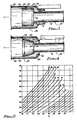
- Equivalent lens diameter was then determined using the graph shown in Fig. 5, which is a grid pattern formed by extending with dotted lines values along the x and y axes of focus voltage as a percent of anode voltage and focusing electrode length (including the lower portion (e.g., 15d in Fig.2) as well as the upper G3B/G3C portion) in millimeters respectively. Overlying the grid pattern are a series of curves each representing a constant value of equivalent lens diameter (RLD) in millimeters. ELD was determined for each electron gun by first locating the intersection of the %Vfoc value and the focusing electrode length, and then noting upon which ELD curve the intersecting point fell. If the point fell between two curves, the ELD value was interpolated as a value between those of the two adjacent curves.
- the focusing electrode length was 50 millimeters.
- the %Vfoc for the prior art gun was 18, resulting in an ELD of 20.5.
- the %Vfoc of the gun of the invention was 18.6, resulting in an ELD of about 19.9, which is 2.9% less than that of the electron gun of the prior art.
Landscapes
- Cathode-Ray Tubes And Fluorescent Screens For Display (AREA)
Applications Claiming Priority (2)
| Application Number | Priority Date | Filing Date | Title |
|---|---|---|---|
| US07/270,989 US4904898A (en) | 1988-11-14 | 1988-11-14 | Monochrome cathode ray tube electron gun with high voltage electrode lens |
| US270989 | 1988-11-14 |
Publications (1)
| Publication Number | Publication Date |
|---|---|
| EP0373684A1 true EP0373684A1 (de) | 1990-06-20 |
Family
ID=23033719
Family Applications (1)
| Application Number | Title | Priority Date | Filing Date |
|---|---|---|---|
| EP89202818A Ceased EP0373684A1 (de) | 1988-11-14 | 1989-11-08 | Elektronenkanone für monochrome Kathodenstrahlröhre |
Country Status (3)
| Country | Link |
|---|---|
| US (1) | US4904898A (de) |
| EP (1) | EP0373684A1 (de) |
| JP (1) | JPH02183944A (de) |
Cited By (1)
| Publication number | Priority date | Publication date | Assignee | Title |
|---|---|---|---|---|
| US6447711B1 (en) | 1995-07-05 | 2002-09-10 | Sinco Engineering, S.P.A. | Polyester resins having improved rheological properties |
Families Citing this family (6)
| Publication number | Priority date | Publication date | Assignee | Title |
|---|---|---|---|---|
| US5621285A (en) * | 1995-05-01 | 1997-04-15 | Zenith Electronics Corporation | Double immersion projection CRT gun |
| JP3539003B2 (ja) * | 1995-10-11 | 2004-06-14 | 三菱電機株式会社 | ブラウン管 |
| US5894190A (en) * | 1996-03-22 | 1999-04-13 | Hitachi, Ltd. | Color cathode ray tube having a large-diameter lens |
| US6031326A (en) | 1997-04-01 | 2000-02-29 | Hitachi, Ltd. | Electron gun with electrode supports |
| KR100310681B1 (ko) | 1999-09-03 | 2001-10-18 | 김순택 | 음극선관용 전자총 |
| JP2002216664A (ja) * | 2001-01-19 | 2002-08-02 | Hitachi Ltd | 陰極線管 |
Citations (2)
| Publication number | Priority date | Publication date | Assignee | Title |
|---|---|---|---|---|
| GB2030763A (en) * | 1978-09-19 | 1980-04-10 | Matsushita Electronics Corp | Electron gun for cathode-ray tube |
| US4469987A (en) * | 1981-10-23 | 1984-09-04 | Zenith Electronics Corporation | Means for enhancing brightness of a monochrome CRT without loss of resolution |
Family Cites Families (3)
| Publication number | Priority date | Publication date | Assignee | Title |
|---|---|---|---|---|
| CA1196677A (en) * | 1982-02-26 | 1985-11-12 | Sony Corporation | Electron gun |
| JPS61273836A (ja) * | 1985-05-28 | 1986-12-04 | Sony Corp | 陰極線管用電子銃 |
| US4634924A (en) * | 1985-08-06 | 1987-01-06 | Rca Corporation | Electron gun having cylindrical focus lens |
-
1988
- 1988-11-14 US US07/270,989 patent/US4904898A/en not_active Expired - Fee Related
-
1989
- 1989-11-08 EP EP89202818A patent/EP0373684A1/de not_active Ceased
- 1989-11-13 JP JP1294755A patent/JPH02183944A/ja active Pending
Patent Citations (2)
| Publication number | Priority date | Publication date | Assignee | Title |
|---|---|---|---|---|
| GB2030763A (en) * | 1978-09-19 | 1980-04-10 | Matsushita Electronics Corp | Electron gun for cathode-ray tube |
| US4469987A (en) * | 1981-10-23 | 1984-09-04 | Zenith Electronics Corporation | Means for enhancing brightness of a monochrome CRT without loss of resolution |
Non-Patent Citations (1)
| Title |
|---|
| PATENT ABSTRACTS OF JAPAN, unexamined applications, E field, vol. 7, no. 45, February 23, 1983 THE PATENT OFFICE JAPANESE GOVERNMENT, page 67 E 160 * |
Cited By (1)
| Publication number | Priority date | Publication date | Assignee | Title |
|---|---|---|---|---|
| US6447711B1 (en) | 1995-07-05 | 2002-09-10 | Sinco Engineering, S.P.A. | Polyester resins having improved rheological properties |
Also Published As
| Publication number | Publication date |
|---|---|
| US4904898A (en) | 1990-02-27 |
| JPH02183944A (ja) | 1990-07-18 |
Similar Documents
| Publication | Publication Date | Title |
|---|---|---|
| US4904898A (en) | Monochrome cathode ray tube electron gun with high voltage electrode lens | |
| US3524094A (en) | Wide deflection angle cathode-ray tube with a lens for focussing the electron-beam at an elongate spot on a screen and an astigmatic correcting lens | |
| US6437498B2 (en) | Wide-angle deflection color cathode ray tube with a reduced dynamic focus voltage | |
| JPH06251722A (ja) | 陰極線管 | |
| US6288482B1 (en) | Color cathode ray tube with reduced drive voltage | |
| JPH056742A (ja) | 陰極線管 | |
| US4682963A (en) | High voltage processing of CRT mounts | |
| JP3171455B2 (ja) | カラー受像管 | |
| US4496877A (en) | Unipotential electron gun for short cathode ray tubes | |
| EP0589522B1 (de) | Kathodenstrahlröhre | |
| US6509680B2 (en) | Electron gun display device provided with an electron gun | |
| JPH10289673A (ja) | 陰極線管 | |
| EP0635862B1 (de) | Kathodenstrahlröhre | |
| US6744190B2 (en) | Cathode ray tube with modified in-line electron gun | |
| KR100617211B1 (ko) | 칼라 음극선관용 전자총 | |
| KR100759406B1 (ko) | 음극선관용 전자총 | |
| KR950004851Y1 (ko) | 칼라 음극선관용 b-u 타입 전자총의 g₃ 계 방전구조 | |
| US5243254A (en) | Electron gun for color picture tube | |
| JPH11195390A (ja) | 陰極線管用インライン型電子銃 | |
| US20060043868A1 (en) | Electron gun assembly and cathode ray tube with the same | |
| US20060108909A1 (en) | Color cathode ray tube and electron gun used therein | |
| JPH05343002A (ja) | 陰極線管 | |
| WO2000034977A1 (fr) | Canon a electrons et tube a rayons cathodiques equipe de celui-ci | |
| JPH06196106A (ja) | 陰極線管を具える装置 | |
| JPH0312423B2 (de) |
Legal Events
| Date | Code | Title | Description |
|---|---|---|---|
| PUAI | Public reference made under article 153(3) epc to a published international application that has entered the european phase |
Free format text: ORIGINAL CODE: 0009012 |
|
| AK | Designated contracting states |
Kind code of ref document: A1 Designated state(s): DE FR GB IT NL |
|
| 17P | Request for examination filed |
Effective date: 19901218 |
|
| 17Q | First examination report despatched |
Effective date: 19930201 |
|
| STAA | Information on the status of an ep patent application or granted ep patent |
Free format text: STATUS: THE APPLICATION HAS BEEN REFUSED |
|
| 18R | Application refused |
Effective date: 19930722 |