EP0373293A2 - Injection molding rack and pinion valve pin actuating mechanism - Google Patents
Injection molding rack and pinion valve pin actuating mechanism Download PDFInfo
- Publication number
- EP0373293A2 EP0373293A2 EP89114133A EP89114133A EP0373293A2 EP 0373293 A2 EP0373293 A2 EP 0373293A2 EP 89114133 A EP89114133 A EP 89114133A EP 89114133 A EP89114133 A EP 89114133A EP 0373293 A2 EP0373293 A2 EP 0373293A2
- Authority
- EP
- European Patent Office
- Prior art keywords
- valve pin
- rack member
- injection molding
- manifold
- molding system
- Prior art date
- Legal status (The legal status is an assumption and is not a legal conclusion. Google has not performed a legal analysis and makes no representation as to the accuracy of the status listed.)
- Granted
Links
- 238000001746 injection moulding Methods 0.000 title claims abstract description 25
- 230000007246 mechanism Effects 0.000 title abstract description 16
- 239000000155 melt Substances 0.000 claims abstract description 12
- 230000006872 improvement Effects 0.000 claims description 2
- 230000007257 malfunction Effects 0.000 abstract description 3
- 238000002347 injection Methods 0.000 description 5
- 239000007924 injection Substances 0.000 description 5
- 238000001816 cooling Methods 0.000 description 3
- 238000010438 heat treatment Methods 0.000 description 3
- 238000009413 insulation Methods 0.000 description 2
- 239000000463 material Substances 0.000 description 2
- 238000000465 moulding Methods 0.000 description 2
- 229920000122 acrylonitrile butadiene styrene Polymers 0.000 description 1
- 239000004676 acrylonitrile butadiene styrene Substances 0.000 description 1
- 230000009471 action Effects 0.000 description 1
- 239000000498 cooling water Substances 0.000 description 1
- 230000001419 dependent effect Effects 0.000 description 1
- 238000006073 displacement reaction Methods 0.000 description 1
- 238000003754 machining Methods 0.000 description 1
- 230000004048 modification Effects 0.000 description 1
- 238000012986 modification Methods 0.000 description 1
- 229920003023 plastic Polymers 0.000 description 1
- 239000004033 plastic Substances 0.000 description 1
- 239000004417 polycarbonate Substances 0.000 description 1
- 229920000515 polycarbonate Polymers 0.000 description 1
- 239000004800 polyvinyl chloride Substances 0.000 description 1
- 229920000915 polyvinyl chloride Polymers 0.000 description 1
- 238000005086 pumping Methods 0.000 description 1
- 229910001220 stainless steel Inorganic materials 0.000 description 1
- 239000010935 stainless steel Substances 0.000 description 1
- 239000010409 thin film Substances 0.000 description 1
Images


Classifications
-
- B—PERFORMING OPERATIONS; TRANSPORTING
- B29—WORKING OF PLASTICS; WORKING OF SUBSTANCES IN A PLASTIC STATE IN GENERAL
- B29C—SHAPING OR JOINING OF PLASTICS; SHAPING OF MATERIAL IN A PLASTIC STATE, NOT OTHERWISE PROVIDED FOR; AFTER-TREATMENT OF THE SHAPED PRODUCTS, e.g. REPAIRING
- B29C45/00—Injection moulding, i.e. forcing the required volume of moulding material through a nozzle into a closed mould; Apparatus therefor
- B29C45/17—Component parts, details or accessories; Auxiliary operations
- B29C45/26—Moulds
- B29C45/27—Sprue channels ; Runner channels or runner nozzles
- B29C45/28—Closure devices therefor
- B29C45/2806—Closure devices therefor consisting of needle valve systems
- B29C45/281—Drive means therefor
- B29C2045/2834—Needle valves driven by a lever
-
- B—PERFORMING OPERATIONS; TRANSPORTING
- B29—WORKING OF PLASTICS; WORKING OF SUBSTANCES IN A PLASTIC STATE IN GENERAL
- B29C—SHAPING OR JOINING OF PLASTICS; SHAPING OF MATERIAL IN A PLASTIC STATE, NOT OTHERWISE PROVIDED FOR; AFTER-TREATMENT OF THE SHAPED PRODUCTS, e.g. REPAIRING
- B29C45/00—Injection moulding, i.e. forcing the required volume of moulding material through a nozzle into a closed mould; Apparatus therefor
- B29C45/17—Component parts, details or accessories; Auxiliary operations
- B29C45/26—Moulds
- B29C45/27—Sprue channels ; Runner channels or runner nozzles
- B29C45/28—Closure devices therefor
- B29C45/2806—Closure devices therefor consisting of needle valve systems
- B29C45/281—Drive means therefor
- B29C2045/2837—Needle valves driven by rack and pinion
Definitions
- the invention provides a valve gated hot runner injection molding system having a heated nozzle which is seated in a cavity plate and secured to a heated manifold, a pneumatically activated elongated valve pin which reciprocates longitudinally between a retracted open position and a forward closed position in a central bore in the nozzle which is in alignment with a gate extending through the cavity plate to a cavity, the valve pin having a driven end and a tip end which seats in the gate in the closed position, a melt passage to convey pressurized melt from an inlet in the manifold to the gate which extends through the manifold and along the valve pin in the central bore of the nozzle, and a valve pin bushing which is seated in the nozzle with a rearwardly extending portion which projects into the manifold, the valve pin bushing having a valve pin bore extending therethrough in alignment with the central bore of the nozzle to receive the valve pin therethrough to prevent substantial leakage of the pressurized melt around the reciprocating
- the manifold 14 is secured in correct alignment to the nozzle 18 by bolts 48.
- the nozzle 18 and manifold 14 are in turn held in place by a locating ring 50 which is secured by bolts 52 extending through the support plate 54 into the cavity plate 32.
- the slot 74 in the manifold 14 extends radially outward to receive the pinion member 84 which is pivotally mounted on a pivot pin 86 which extends into the manifold 14 on opposite sides of the slot 74.
- the pinion member 84 also has teeth 88 which engage the teeth 82 of the rack member 76 and a pivot arm 90 which extends outwardly through the mouth 92 of the slot 74.
- the pivot arm 90 is connected by a rod 94 to a double-acting piston 96 which is driven by air received through hoses (not shown) to connectors 98 to reciprocate in a pivotally mounted cylinder 100. While the pivot arm 90 is curved in this embodiment to match the location of the cylinder 100 and piston 96, other suitable arrangements can be used to drive the pinion member 84.
Abstract
Description
- This invention relates generally to injection molding and more particularly to a valve gated hot runner injection molding system having a pneumatically driven rack and pinion valve pin actuating mechanism.
- Valve gated injection molding systems are well known in the art, as are the related problems of valve pin actuating mechanisms. Actuating mechanisms are usually either lever operated or piston operated. A lever operated mechanism is shown in the applicant's U.S. patent number 4,222,733 which issued September 16, 1980. While this arrangement is satisfactory for many applications, it has the disadvantage that the lever unavoidably applied a lateral force to the reciprocating valve pin which causes friction, uneven wear and a larger gap on one side than the other. As a result, during the operating life of the system there is an uneven buildup of melt deposits around the valve pin which can cause leakage and malfunction. Other examples of lever operated valve pin mechanisms having similar problems are shown in the following brochures; Incoe "SVG 5000, SVG 7000", H. Muller Mekaniska AB "Flytgot Typ N" and "Precusion Products GmbH Delta" Spritzduse Mit Hydraulicverschluss.
- Actuating mechanisms having a piston connected directly to the valve pin have been used to overcome these problems associated with lever operated mechanisms. Examples of such piston operated mechanisms are shown in U.S. patent numbers 4,380,426 to Wiles which issued April 19, 1983, 4,433,969 to the applicant which issued February 24, 1984 and 4,755,131 to Schmidt which issued July 5, 1988. While these piston operated systems do reduce the lateral forces applied to the valve pin they have the disadvantage that they are relatively costly to make and require a considerable amount of space around the valve pin head to which the piston is connected. This is particularly a problem in providing for the melt passage in a center entry single nozzle system as described in U.S. patent number 4,380,426 referred to above. Also, many of the piston operated systems are hydraulically driven which has the additional problems of hot seals and continuing to circulate the oil for cooling after shut down. Furthermore, in a stack molding configuration the additional height required for the actuating mechanism is a considerable disadvantage.
- Accordingly, it is an object of the invention to at least partially overcome the problems of the prior art by providing a pneumatically driven rack and pinion valve pin actuating mechanism for a hot runner injection molding system.
- To this end, in one of its aspects, the invention provides a valve gated hot runner injection molding system having a heated nozzle which is seated in a cavity plate and secured to a heated manifold, a pneumatically activated elongated valve pin which reciprocates longitudinally between a retracted open position and a forward closed position in a central bore in the nozzle which is in alignment with a gate extending through the cavity plate to a cavity, the valve pin having a driven end and a tip end which seats in the gate in the closed position, a melt passage to convey pressurized melt from an inlet in the manifold to the gate which extends through the manifold and along the valve pin in the central bore of the nozzle, and a valve pin bushing which is seated in the nozzle with a rearwardly extending portion which projects into the manifold, the valve pin bushing having a valve pin bore extending therethrough in alignment with the central bore of the nozzle to receive the valve pin therethrough to prevent substantial leakage of the pressurized melt around the reciprocating valve pin, the improvement wherein a rack member longitudinally slidably received in an opening in the manifold to engage the driven end of the valve pin, the rack member having a toothed portion with a longitudinal row of teeth which face outwardly in the radial opening, a pivotally mounted pinion member with a plurality of teeth which engage the teeth of the rack member, and double acting pneumatic actuating means connected to pivot the pinon member through a predetermined angle according to a predetermined cycle whereby the rack member and the valve pin are reciprocated longitudinally between the open and closed positions.
- Further objects and advantages of the invention will appear from the following description, taken together with the accompanying drawings.
-
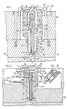
- Figure 1 is a sectional view of a portion of an injection molding system according to one embodiment of the invention showing the melt flow passage,
- Figure 2 is a sectional view taken along line 2-2 in Figure 1 showing the actuating mechanism with the valve pin in the closed position,
- Figure 3 is a similar view to Figure 2 showing the valve pin in the open position,
- Figure 4 is a cut-away isometric view showing how the rack member is received in the manifold,
- Figure 5 is a sectional view of a portion of an injection molding system according to a second embodiment of the invention, and
- Figure 6 is a cut-away isometric view showing how the rack member in Figure 5 abuts against the valve pin bushing.
- Reference is first made to Figure 1 which shows a valve gated injection molding system having a
melt passage 10 which extends from acentral inlet 12 in amanifold 14, through acentral bore 16 of anozzle 18 and agate 20 to acavity 22. As can be seen, in this embodiment themelt passage 10 branches from thecentral inlet 12 into twochannels 24 around the valve pin actuating mechanism, rejoins in a valve pin bushing 26 which is seated in thenozzle 18, and extends along thevalve pin 28 in thecentral bore 16 which is considerably larger in diameter than thevalve pin 28. Thecentral bore 16 extends through astainless steel liner 29 similar to that shown in the applicant's U.S. patent number 4,451,974 which issued June 5, 1984. - The
nozzle 18 is seated in awell 30 in thecavity plate 32 by an insulation flange or bushing 34 which abuts against a circumferential shoulder 36. This accurately locates thenozzle 18 with thecentral bore 16 in alignment with thegate 20 and provides aninsulative air space 38 between thenozzle 18 and the surroundingcavity plate 32. Thenozzle 18 has an electrical heating element 40 which is integrally cast into it and thecavity plate 32 is cooled by pumping cooling water throughcooling conduits 42. An injectionmolding nozzle seal 44 as described in the applicant's U.S. patent number 4,286,941 which issued September 1, 1981 is seated in thenose portion 46 of thenozzle 18 and bridges theair space 38 around thegate 20 to prevent theair space 38 filling with melt. - The
manifold 14 is secured in correct alignment to thenozzle 18 bybolts 48. Thenozzle 18 andmanifold 14 are in turn held in place by a locatingring 50 which is secured bybolts 52 extending through thesupport plate 54 into thecavity plate 32. - The valve pin busing 26 is securely seated in an opening 56 in the rear face 58 of the
nozzle 18 and has a valve pin bore 60 extending therethrough in alignment with thecentral bore 16 through thenozzle 18. As described in U.S. patent number 4,433,969, the valve pin bore 60 which extends into a rearwardly projectingportion 62 is of sufficient length and fits snugly enough around thevalve pin 28 to seal against leakage of the pressurized melt around thevalve pin 28 as it reciprocates. As can be seen, the valve pin bushing 26 is shaped to connect the twochannel 24 of themelt passage 10 to thecentral bore 16 through thenozzle 18. The valve pin bushing 26 and the opening 56 in which it is seated in thenozzle 18 are oblong shaped to accurately align it, and the rearwardly projectingportion 62 has an outwardly facingflat surface 64. - The
elongated valve pin 28 has an enlargedhead 66 at the drivenend 68 and atip end 70 which seats in thegate 20 in the forward closed position. Themanifold 14 is heated by anelectrical heating element 72 which is integrally brazed into it. Themanifold 14 is made with a slot orradial opening 74 which receives the rearwardly projectingportion 62 of the valve pin bushing 26 and therack member 76. Therack member 76 has a T-slot 78 which engages the enlargedhead 66 of thevalve pin 28 and atoothed portion 80 with a row of outwardly facingteeth 82. Theslot 74 in themanifold 14 extends radially outward to receive thepinion member 84 which is pivotally mounted on apivot pin 86 which extends into themanifold 14 on opposite sides of theslot 74. Thepinion member 84 also hasteeth 88 which engage theteeth 82 of therack member 76 and apivot arm 90 which extends outwardly through themouth 92 of theslot 74. Thepivot arm 90 is connected by arod 94 to a double-actingpiston 96 which is driven by air received through hoses (not shown) toconnectors 98 to reciprocate in a pivotally mountedcylinder 100. While thepivot arm 90 is curved in this embodiment to match the location of thecylinder 100 andpiston 96, other suitable arrangements can be used to drive thepinion member 84. - In use, the system is assembled as shown and electrical power is applied to the terminals 102,104 of the
heating elements 40,72 to heat themanifold 14 and thenozzle 18 to a predetermined operating temperature. Pressurized melt from a molding machine (not shown) is introduced into themelt passage 10 through thecentral inlet 12 according to a predetermined cycle and controlled pneumatic pressure is applied through the hoses to theconnectors 98 to operate thepiston 96 according to a matching cycle. When thepiston 96 pivots thepinion member 84 to the open position shown in Figure 3, therack member 76 and thevalve pin 28 slide rearwardly to withdraw thetip end 70 from thegate 20. The pressurized melt flows through themelt passage 10 along thevalve pin 28, through thegate 20 and fills thecavity 22. After the cavity is filled, injection pressure is held momentarily to pack and then thepiston 96 pivots thepinion member 84 to the closed position shown in Figure 2. This causes therack member 76 and thevalve pin 28 to slide forwardly until thetip end 70 is seated in thematching gate 20. Injection pressure is then released and after a short cooling period, the mold is opened along theparting line 106 to eject the molded product. After ejection, the mold is closed, pneumatic pressure is applied to thecylinder 100 to withdraw thevalve pin 28 to the open position, and injection pressure is reapplied to refill thecavity 22. This cycle is repeated continuously with a frequency dependent upon the size of cavity and type of material being molded. - As the
valve pin 28 is reciprocated between the open and closed positions, theteeth 88 of thepinion member 84 engage and drive theteeth 82 of therack member 76. While this unavoidably results in the application of some lateral force to therack member 76, this lateral force is absorbed by contact between theinward surface 108 of therack member 76 and thematching surface 110 of the radial opening orslot 74 in themanifold 14 against which it abuts as it slides. The shape of theslot 74 also keeps therack member 76 and thepinion member 84 in place so theteeth rack member 76 is also absorbed by sliding contact between a flat inwardly facingsurface 112 of thetoothed portion 80 of therack member 76 and the outwardly facingflat surface 64 of the rearwardly projectingportion 62 of the valve pin bushing 26. Thus, therack member 76 travels along a substantially straight line as it reciprocates between the open and closed positions which avoids the application of lateral forces or stress to the drivenend 68 of thevalve pin 28. The relatively loose receipt or engagement of the enlargedhead 66 of thevalve pin 28 in theslot 78 in therack member 76 further ensures that lateral forces are not transmitted to thevalve pin 28 by therack member 76. This allows thevalve pin 28 to reciprocate in the center of the valve pin bore 60 through the valve pin bushing 26 without being displaced to one side. This avoids leakage and malfunction due to uneven wearing and displacement around the reciprocatingvalve pin 28. The double acting actuation of the valve pin allows the valve pin to be opened before injection pressure is applied which avoids a thin film of semicold plastic being injected when injection is initiated which is very advantageous for cosmetically clean gate marks with materials such as polycarbonates, ABS, polyvinyl chloride, and the like. - Figures 5 and 6 show an injection molding system according to another embodiment of the system. As many of the elements of this embodiment are the same as the first embodiment, elements common to both embodiments are described and illustrated using the same reference numerals. In this embodiment, the
melt passage 10 branches from an inlet (not shown) in anelongated manifold 14 to a number of spaced nozzles 18 (only one of which is shown). Eachnozzle 18 is seated in a well 30 in thecavity plate 32 with a structure as described above. In this case, themelt passage 10 has abend 114 in the manifold 14 before extending into thevalve pin bushing 26 where it connects to thecentral bore 16 around thevalve pin 28. Thebend 114 is made by suitably machining aplug 116 which is brazed in place in the manifold 14 as described in U.S. patent number 4,609,138 to Harrison which issued September 2, 1986. - The use of an
elongated manifold 14 provides the additional problem in this embodiment of misalignment due to thermal expansion. While thenozzle 18 is accurately located in the well 30 by theinsulation flange 34, the manifold expands and contracts longitudinally from where it is located in alignment with the central inlet (not shown). Thus it is not satisfactory to have therack member 76 abut against thesurface 110 of theslot 74 in themanifold 14. Rather, thevalve pin bushing 26 has a different configuration with therearwardly projecting portion 62 extending further into theslot 74 and having aspace 118 between it and thesurface 110 of theslot 74. As clearly seen in Figure 6, therearwardly projecting portion 62 of thevalve pin bushing 26 has a rearward outwardly facingflat surface 120 and a forward outwardly facingflat surface 122. Therack member 76 also has a rearwardly inwardly facingflat surface 124 and a forward inwardly facingflat surface 126. As shown, the flat surfaces 124,126 of therack member 76 abut against the flat surfaces 120,122 of therearwardly projecting portion 62 of thevalve pin bushing 26 as therack member 76 and valve pin 228 are reciprocated by the pivotal action of thepinion member 84. Thus, substantially all of the lateral forces applied by thepinion member 84 to therack member 76 are absorbed by thevalve pin bushing 26 and not by thevalve pin 28. As mentioned above, thevalve pin 28 has anenlarged head 66 which is loosely received in a T-slot 78 on therack member 76 which further ensures that lateral forces are not transferred to thevalve pin 28 by therack member 76. While the surfaces 120,122 of thevalve pin bushing 26 and 124,126 of therack member 76 are shown as being flat in this embodiment, they can have other shapes which match sufficiently to provide for the reciprocal sliding motion of therack member 76. Thehead 66 of thevalve pin 28 is made with oneflat side 128 which abuts against the rearward outwardly facingflat surface 120 of thevalve pin bushing 26 to prevent thevalve pin 28 from rotating as it reciprocates. The feature is useful if the valvepin tip end 70 is shaped to fit an angled cavity and/or to provide a textured finish. - The
pinion member 84 and the remainder of the valve pin actuating mechanism is the same as described above in regard to the first embodiment. Similarly, operation of the system is the same and the description need not be repeated. The difference is that in this embodiment the lateral forces from therack member 76 are absorbed entirely by thevalve pin bushing 26, whereas in the first embodiment the lateral forces are split between the manifold 14 and thevalve pin bushing 26. It is, of course, apparent that the first embodiment can also be modified to have all of the lateral forces absorbed only by the manifold in a system where misalignment due to thermal expansion is not a problem. - While the description of the injection molding system with a rack and pinion actuating mechanism has been given with respect to preferred embodiments, it is not to be construed in a limiting sense. Variations and modifications will occur to those skilled in the art. For instance, it is apparent that the shapes and/or configurations of the
pinion member 84,rack member 86 andslot 74 in the manifold 14 can be varied without applying unacceptable lateral forces to the drivenend 68 of thevalve pin 28 as it reciprocates. Reference is made to the appended claims for a definition of the invention.
Claims (12)
Applications Claiming Priority (2)
| Application Number | Priority Date | Filing Date | Title |
|---|---|---|---|
| CA586166 | 1988-12-16 | ||
| CA000586166A CA1303314C (en) | 1988-12-16 | 1988-12-16 | Injection molding rack and pinion valve pin actuating mechanism |
Publications (3)
| Publication Number | Publication Date |
|---|---|
| EP0373293A2 true EP0373293A2 (en) | 1990-06-20 |
| EP0373293A3 EP0373293A3 (en) | 1991-06-12 |
| EP0373293B1 EP0373293B1 (en) | 1995-04-12 |
Family
ID=4139305
Family Applications (1)
| Application Number | Title | Priority Date | Filing Date |
|---|---|---|---|
| EP89114133A Expired - Lifetime EP0373293B1 (en) | 1988-12-16 | 1989-07-31 | Injection molding rack and pinion valve pin actuating mechanism |
Country Status (7)
| Country | Link |
|---|---|
| EP (1) | EP0373293B1 (en) |
| JP (1) | JP2703357B2 (en) |
| CN (1) | CN1021209C (en) |
| AT (1) | ATE121004T1 (en) |
| CA (1) | CA1303314C (en) |
| DE (2) | DE3925348C2 (en) |
| ES (1) | ES2070871T3 (en) |
Cited By (5)
| Publication number | Priority date | Publication date | Assignee | Title |
|---|---|---|---|---|
| WO1996027489A1 (en) * | 1995-03-03 | 1996-09-12 | Stern Christian Rene | Heated tool nozzle |
| EP0781640A2 (en) | 1995-12-23 | 1997-07-02 | EWIKON Heisskanalsysteme GmbH & CO. Kommanditgesellschaft | Heated needle valve nozzle |
| USRE41280E1 (en) | 2003-06-23 | 2010-04-27 | Panos Trakas | Adjustable valve pin assembly |
| US8113818B2 (en) | 2010-03-30 | 2012-02-14 | Panos Trakas | Valve gate system |
| US8697360B2 (en) | 2007-11-30 | 2014-04-15 | Decode Genetics Ehf. | Genetic variants on CHR 11Q and 6Q as markers for prostate and colorectal cancer predisposition |
Families Citing this family (6)
| Publication number | Priority date | Publication date | Assignee | Title |
|---|---|---|---|---|
| DE19757412C1 (en) | 1997-12-23 | 1999-02-25 | Knauer Systec Eng Gmbh | Hot runner injection moulding tool with a needle valve shut=off and compact economical construction |
| JP3991340B2 (en) * | 1998-04-07 | 2007-10-17 | 株式会社十王 | Injection molding nozzle |
| US7207790B2 (en) | 2004-07-02 | 2007-04-24 | Panos Trakas | Needle assembly with adjustable gating needle position for injection molding nozzle |
| CA2567936C (en) | 2006-11-14 | 2016-01-05 | Atomic Energy Of Canada Limited | Device and method for surface replication |
| CN110461566B (en) * | 2017-04-18 | 2022-01-11 | 圣万提注塑工业(苏州)有限公司 | Linear to linear valve pin actuation during injection cycles |
| CN110091470B (en) * | 2018-01-27 | 2021-06-15 | 泰州市创源阀业有限公司 | Two-plate mold of hot nozzle |
Citations (4)
| Publication number | Priority date | Publication date | Assignee | Title |
|---|---|---|---|---|
| DE931677C (en) * | 1952-12-02 | 1955-08-16 | Licentia Gmbh | Injection nozzle for injection molding machines that process thermoplastic masses |
| FR2237750A1 (en) * | 1973-07-16 | 1975-02-14 | Hehl Karl | |
| GB2085350A (en) * | 1980-10-15 | 1982-04-28 | Gellert Jobst U | Injection mould gates |
| EP0099088A2 (en) * | 1982-07-12 | 1984-01-25 | Jobst Ulrich Gellert | Injection molding valve pin bushing and method of making it |
Family Cites Families (5)
| Publication number | Priority date | Publication date | Assignee | Title |
|---|---|---|---|---|
| DE2336099A1 (en) * | 1973-07-16 | 1975-02-06 | Hehl Karl | Hydraulically regulated nozzle for an injection moulding machine - opening and closing precisely, held closed mechanically during changeover |
| CA1097873A (en) * | 1978-12-14 | 1981-03-24 | Jobst U. Gellert | Injection molding flow control mechanism |
| CA1174820A (en) * | 1982-02-24 | 1984-09-25 | William J. Wiles | Injection molding valve pin direct pneumatic actuator |
| US4530654A (en) * | 1984-05-29 | 1985-07-23 | Mold-Masters Limited | Injection molding peripheral opening core ring gate |
| CA1259156A (en) * | 1986-10-31 | 1989-09-12 | Harald H. Schmidt | Fluid cooled hydraulic actuating mechanism for single cavity injection molding |
-
1988
- 1988-12-16 CA CA000586166A patent/CA1303314C/en not_active Expired - Lifetime
-
1989
- 1989-07-31 AT AT89114133T patent/ATE121004T1/en not_active IP Right Cessation
- 1989-07-31 DE DE3925348A patent/DE3925348C2/en not_active Expired - Lifetime
- 1989-07-31 ES ES89114133T patent/ES2070871T3/en not_active Expired - Lifetime
- 1989-07-31 DE DE68922194T patent/DE68922194T2/en not_active Expired - Lifetime
- 1989-07-31 EP EP89114133A patent/EP0373293B1/en not_active Expired - Lifetime
- 1989-08-18 JP JP1212843A patent/JP2703357B2/en not_active Expired - Lifetime
- 1989-09-01 CN CN89106623.3A patent/CN1021209C/en not_active Expired - Lifetime
Patent Citations (4)
| Publication number | Priority date | Publication date | Assignee | Title |
|---|---|---|---|---|
| DE931677C (en) * | 1952-12-02 | 1955-08-16 | Licentia Gmbh | Injection nozzle for injection molding machines that process thermoplastic masses |
| FR2237750A1 (en) * | 1973-07-16 | 1975-02-14 | Hehl Karl | |
| GB2085350A (en) * | 1980-10-15 | 1982-04-28 | Gellert Jobst U | Injection mould gates |
| EP0099088A2 (en) * | 1982-07-12 | 1984-01-25 | Jobst Ulrich Gellert | Injection molding valve pin bushing and method of making it |
Cited By (7)
| Publication number | Priority date | Publication date | Assignee | Title |
|---|---|---|---|---|
| WO1996027489A1 (en) * | 1995-03-03 | 1996-09-12 | Stern Christian Rene | Heated tool nozzle |
| EP0781640A2 (en) | 1995-12-23 | 1997-07-02 | EWIKON Heisskanalsysteme GmbH & CO. Kommanditgesellschaft | Heated needle valve nozzle |
| DE19548687B4 (en) * | 1995-12-23 | 2004-01-08 | EWIKON Heißkanalsysteme GmbH & Co KG | Heated valve gate |
| USRE41280E1 (en) | 2003-06-23 | 2010-04-27 | Panos Trakas | Adjustable valve pin assembly |
| US8697360B2 (en) | 2007-11-30 | 2014-04-15 | Decode Genetics Ehf. | Genetic variants on CHR 11Q and 6Q as markers for prostate and colorectal cancer predisposition |
| US8113818B2 (en) | 2010-03-30 | 2012-02-14 | Panos Trakas | Valve gate system |
| US8449799B2 (en) | 2010-03-30 | 2013-05-28 | Panos Trakas | Valve gate system |
Also Published As
| Publication number | Publication date |
|---|---|
| CA1303314C (en) | 1992-06-16 |
| DE68922194D1 (en) | 1995-05-18 |
| JPH02214632A (en) | 1990-08-27 |
| ES2070871T3 (en) | 1995-06-16 |
| DE3925348C2 (en) | 1999-12-02 |
| DE3925348A1 (en) | 1990-06-21 |
| EP0373293A3 (en) | 1991-06-12 |
| CN1043464A (en) | 1990-07-04 |
| JP2703357B2 (en) | 1998-01-26 |
| CN1021209C (en) | 1993-06-16 |
| ATE121004T1 (en) | 1995-04-15 |
| EP0373293B1 (en) | 1995-04-12 |
| DE68922194T2 (en) | 1995-08-17 |
Similar Documents
| Publication | Publication Date | Title |
|---|---|---|
| US4919606A (en) | Injection molding rack and pinion valve pin actuating mechanism | |
| US5049062A (en) | Injection molding system having spring biased nozzles | |
| US5849343A (en) | Injection molding apparatus with a one-piece gate insert locating a cylindrical valve member | |
| CA1252973A (en) | Side mounted manifold block for variable orientation of injection molding nozzle | |
| US4932858A (en) | Injection molding system having dual feed bushing seated in manifold | |
| US4712995A (en) | Replaceable rocker arm assembly for injection molding system | |
| US5387099A (en) | Injection molding valve member sealing bushing with a thin collar portion | |
| US5022846A (en) | Pneumatic actuating mechanism for injection molding | |
| US4747770A (en) | Fluid cooled hydraulic actuating mechanism for injection molding | |
| EP0657270B1 (en) | Valve gated injection molding apparatus with a spring in the piston | |
| EP0614743B1 (en) | Injection molding nozzle insert with valve member locating blades | |
| US4530654A (en) | Injection molding peripheral opening core ring gate | |
| EP0385175A2 (en) | Injection molding system with gas flow through valve gate | |
| EP0373293B1 (en) | Injection molding rack and pinion valve pin actuating mechanism | |
| US4786246A (en) | Injection molding multiple nozzle valve gating system | |
| US6162044A (en) | Multi-cavity injection molding apparatus splitting melt near nozzle front | |
| CA1309819C (en) | Injection molding system having valve member split ring | |
| EP0106980A1 (en) | Injection molding core ring gate | |
| US4938681A (en) | Injection molding system having offset valve pin biasing mechanism | |
| US4931009A (en) | Injection molding system having a thermal locating flange | |
| CA2010381A1 (en) | Valve gated sequential injection molding apparatus | |
| CA1311893C (en) | Injection molding system with gas flow through valve gate | |
| WO2000051803A1 (en) | Multi-cavity injection molding apparatus splitting melt near nozzle front | |
| CA2019707A1 (en) | Injection molding apparatus with direct gas connection to valve member |
Legal Events
| Date | Code | Title | Description |
|---|---|---|---|
| PUAI | Public reference made under article 153(3) epc to a published international application that has entered the european phase |
Free format text: ORIGINAL CODE: 0009012 |
|
| AK | Designated contracting states |
Kind code of ref document: A2 Designated state(s): AT BE CH DE ES FR GB GR IT LI LU NL SE |
|
| PUAL | Search report despatched |
Free format text: ORIGINAL CODE: 0009013 |
|
| AK | Designated contracting states |
Kind code of ref document: A3 Designated state(s): AT BE CH DE ES FR GB GR IT LI LU NL SE |
|
| 17P | Request for examination filed |
Effective date: 19911204 |
|
| 17Q | First examination report despatched |
Effective date: 19930528 |
|
| GRAA | (expected) grant |
Free format text: ORIGINAL CODE: 0009210 |
|
| AK | Designated contracting states |
Kind code of ref document: B1 Designated state(s): AT BE CH DE ES FR GB GR IT LI LU NL SE |
|
| PG25 | Lapsed in a contracting state [announced via postgrant information from national office to epo] |
Ref country code: GR Free format text: LAPSE BECAUSE OF FAILURE TO SUBMIT A TRANSLATION OF THE DESCRIPTION OR TO PAY THE FEE WITHIN THE PRESCRIBED TIME-LIMIT Effective date: 19950412 |
|
| REF | Corresponds to: |
Ref document number: 121004 Country of ref document: AT Date of ref document: 19950415 Kind code of ref document: T |
|
| ITF | It: translation for a ep patent filed |
Owner name: MARCHI & MITTLER S.R.L. |
|
| REF | Corresponds to: |
Ref document number: 68922194 Country of ref document: DE Date of ref document: 19950518 |
|
| REG | Reference to a national code |
Ref country code: ES Ref legal event code: FG2A Ref document number: 2070871 Country of ref document: ES Kind code of ref document: T3 |
|
| ET | Fr: translation filed | ||
| PLBE | No opposition filed within time limit |
Free format text: ORIGINAL CODE: 0009261 |
|
| STAA | Information on the status of an ep patent application or granted ep patent |
Free format text: STATUS: NO OPPOSITION FILED WITHIN TIME LIMIT |
|
| 26N | No opposition filed | ||
| REG | Reference to a national code |
Ref country code: GB Ref legal event code: IF02 |
|
| REG | Reference to a national code |
Ref country code: CH Ref legal event code: PUE Owner name: MOLD-MASTERS (2007) LIMITED Free format text: JOBST ULRICH GELLERT#7A PRINCE STREET#GEORGETOWN/ONTARIO (CA) -TRANSFER TO- MOLD-MASTERS (2007) LIMITED#233 ARMSTRONG AVENUE#GEORGETOWN ON L7G4X5 (CA) |
|
| REG | Reference to a national code |
Ref country code: GB Ref legal event code: 732E |
|
| NLS | Nl: assignments of ep-patents |
Owner name: MOLD-MASTERS (2007) LIMITED Effective date: 20080610 |
|
| PGFP | Annual fee paid to national office [announced via postgrant information from national office to epo] |
Ref country code: LU Payment date: 20080710 Year of fee payment: 20 Ref country code: CH Payment date: 20080708 Year of fee payment: 20 Ref country code: DE Payment date: 20080730 Year of fee payment: 20 Ref country code: ES Payment date: 20080718 Year of fee payment: 20 |
|
| PGFP | Annual fee paid to national office [announced via postgrant information from national office to epo] |
Ref country code: NL Payment date: 20080711 Year of fee payment: 20 Ref country code: IT Payment date: 20080717 Year of fee payment: 20 Ref country code: FR Payment date: 20080730 Year of fee payment: 20 Ref country code: AT Payment date: 20080714 Year of fee payment: 20 |
|
| REG | Reference to a national code |
Ref country code: FR Ref legal event code: TP |
|
| PGFP | Annual fee paid to national office [announced via postgrant information from national office to epo] |
Ref country code: GB Payment date: 20080630 Year of fee payment: 20 |
|
| PGFP | Annual fee paid to national office [announced via postgrant information from national office to epo] |
Ref country code: BE Payment date: 20080722 Year of fee payment: 20 Ref country code: SE Payment date: 20080626 Year of fee payment: 20 |
|
| REG | Reference to a national code |
Ref country code: CH Ref legal event code: PL |
|
| REG | Reference to a national code |
Ref country code: GB Ref legal event code: PE20 Expiry date: 20090730 |
|
| REG | Reference to a national code |
Ref country code: ES Ref legal event code: FD2A Effective date: 20090801 |
|
| NLV7 | Nl: ceased due to reaching the maximum lifetime of a patent |
Effective date: 20090731 |
|
| EUG | Se: european patent has lapsed | ||
| PG25 | Lapsed in a contracting state [announced via postgrant information from national office to epo] |
Ref country code: ES Free format text: LAPSE BECAUSE OF EXPIRATION OF PROTECTION Effective date: 20090801 |
|
| PG25 | Lapsed in a contracting state [announced via postgrant information from national office to epo] |
Ref country code: NL Free format text: LAPSE BECAUSE OF EXPIRATION OF PROTECTION Effective date: 20090731 Ref country code: GB Free format text: LAPSE BECAUSE OF EXPIRATION OF PROTECTION Effective date: 20090730 |