EP0372530B1 - Apparatus for applying lubricant to molding die in machine for making glass bottles - Google Patents
Apparatus for applying lubricant to molding die in machine for making glass bottles Download PDFInfo
- Publication number
- EP0372530B1 EP0372530B1 EP89122491A EP89122491A EP0372530B1 EP 0372530 B1 EP0372530 B1 EP 0372530B1 EP 89122491 A EP89122491 A EP 89122491A EP 89122491 A EP89122491 A EP 89122491A EP 0372530 B1 EP0372530 B1 EP 0372530B1
- Authority
- EP
- European Patent Office
- Prior art keywords
- spraying
- lubricant
- spraying nozzle
- molding die
- nozzle
- Prior art date
- Legal status (The legal status is an assumption and is not a legal conclusion. Google has not performed a legal analysis and makes no representation as to the accuracy of the status listed.)
- Expired - Lifetime
Links
Images


Classifications
-
- C—CHEMISTRY; METALLURGY
- C03—GLASS; MINERAL OR SLAG WOOL
- C03B—MANUFACTURE, SHAPING, OR SUPPLEMENTARY PROCESSES
- C03B40/00—Preventing adhesion between glass and glass or between glass and the means used to shape it, hold it or support it
- C03B40/02—Preventing adhesion between glass and glass or between glass and the means used to shape it, hold it or support it by lubrication; Use of materials as release or lubricating compositions
- C03B40/027—Apparatus for applying lubricants to glass shaping moulds or tools
Landscapes
- Chemical & Material Sciences (AREA)
- Engineering & Computer Science (AREA)
- Materials Engineering (AREA)
- Organic Chemistry (AREA)
- Re-Forming, After-Treatment, Cutting And Transporting Of Glass Products (AREA)
- Spray Control Apparatus (AREA)
- Surface Treatment Of Glass (AREA)
Description
- The invention relates to an apparatus for applying lubricant onto the molding dies in a glass bottle making machine, comprising at least one spraying nozzle for spraying a mist of lubricant mixed with air onto an inner surface of each said molding dies, said spraying nozzle being located in a space defined above said molding dies, and an actuator which is connected to the spraying nozzle to reciprocally move the latter between a spraying position in which the spraying nozzle is located directly above each of said molding dies to spray the mist of lubricant onto the inner surface of each of said molding dies and an inoperative position apart from the spraying position.
- In a glass bottle making machine, lubricant, such as an oil containing carbon powder or the like is applied onto a molding surface of a molding die, for example to ensure a smooth charge of a gob (gob of molten glass) into a molding cavity and a smooth release of a molded product from the molding cavity. The application of such a lubricant is manually effected at an interval of molding cycle in which a predetermined number of molded products are produced.
- An apparatus for applying lubricant onto a molding die of a glass bottle making machine is known from FR-A-2 078 024. This known apparatus comprises for each molding die of the glass bottle making machine a spraying nozzle wherein the spraying nozzles of two adjacent molding dies are attached on a common arm. This arm can be moved reciprocally from a spraying position to an inoperative position, respectively. Since the spraying action only takes a short moment most of the time spraying nozzles are in their inoperative position. Due to this reason the known apparatus is relatively expensive.
- A further apparatus for applying lubricant onto a molding die of a glass bottle making machine is known from GB-A-2 132 188. Hereby, a spraying nozzle is also provided for each molding die. Therefore, the same disadvantage arises from this known apparatus as described in connection with the apparatus known from FR-A-2 078 024.
- It is an object of the present invention to provide an apparatus for applying lubricant onto molding dies in a glass bottle making machine according to the precharacterizing clause of Claim 1 which is simple and inexpensive in its construction.
- To achieve the object of the present invention the apparatus further comprises a guide rail along which the spraying nozzle moves corresponding to the sets of molding dies comprised in an array of a plurality of molding sections constituting the glass bottle making machine. The proposed solution permits that only one spraying nozzle unit is necessary for the plurality of molding dies for glass bottle making machines.
- The invention will be described below in detail with reference to the accompanying drawings, in which:
- Fig. 1 is a side elevational view of an apparatus for applying lubricant onto a molding die in a glass bottle making machine, according to an aspect of the present invention;
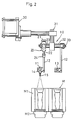
- Fig. 2 is a front elevational view of Fig. 1;
- Fig. 3 is a side elevational view of an apparatus for applying lubricant onto a molding die in a glass bottle making machine, according to another aspect of the present invention;
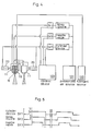
- Fig. 4 is a schematic block diagram showing the operation of an apparatus for applying lubricant onto a molding die in a glass bottle making machine, according to the present invention;
- Fig. 5 is a timing chart of the operations in an apparatus for applying lubricant onto a molding die in a glass bottle making machine, according to the present invention; and,
- Fig. 6 is a schematic plan view of an apparatus for applying lubricant onto a molding die according to the present invention in connection with the operations of a glass bottle making machine to which the present invention is applied.
- As can be seen from Figs. 1 and 2, a
lubricant applying apparatus 10 of the present invention has a sprayingnozzle 11 which has an ejection opening 15 and which is located above a molding die M of a glass bottle making machine to intermittently spray a mist of lubricant mixed with air onto an inner surface of a rough molding die M1 and a mouth molding die M2 of the molding die M. - The
lubricant applying apparatus 10 is placed so that it does not interfere with the operations of devices (not shown) of a glass bottle making machine, such as a delivering device or a baffle, located above the rough molding die M1. To this end, in the illustrated embodiment,lubricant applying apparatus 10 is located above to be offset from the axis of the molding die M. That is, thelubricant applying apparatus 10 is located in a space defined above in an inclined direction with respect to the molding die M. - The
nozzle 11 can be reciprocally moved between an inoperative position W in which the nozzle does not interfer with the operations of the various devices (not shown) of the glass bottle making machine located above the molding die M and an operative position, i.e. a spraying position S in which thenozzle 11 is located directly above the molding die M so as to spray the lubricant (mist) into the molding die M. The actuator for reciprocally moving thenozzle 11 between the operative position S and the inoperative position W will be described hereinafter. - As shown in Fig. 2, the spraying
nozzle 11 is attached to amounting hole 13 formed at a front end of a generally L-shaped arm 12, by means of aset screw 14. In the illustrated embodiment, twoarms 12 are rotatably connected to opposite ends of ashaft 32 of anarm holder 31 by means of setscrews 33. Thearm holder 31 is integrally connected to amanifold 30. - The actuator of the
nozzle 11, i.e. ahydraulic cylinder device 20 is attached to theshaft 32 through amounting member 21 secured thereto. Thecylinder device 20 has apiston rod 22 which is connected to the L-shaped arm 12, so that the L-shaped arm 12 can be rotated about the axis of theshaft 32 by the operation of the piston rod of thecylinder device 20. - In Figs. 1 and 2,
numeral 23 designates a set screw for securing themounting member 21 to thecylinder device 20, 24 a mounting portion of thepiston rod 22 of the cylinder device and the L-shaped arm 12, and 25 a mounting pin which rotatably connects themounting potion 24 to the L-shaped arm 12. - As can be understood from the above discussion, when the
cylinder device 20 operates to move the L-shaped arms 12, thenozzles 11 reciprocally move in an archwise motion between the operative position S (spraying position) and the inoperative position W. - The reciprocal movements of the
arms 12 and accordingly thenozzles 11 and the spraying of the lubricant (mist) from thenozzles 11 in the operative position S can be effected by a same pneumatic pressure source, as shown in Fig. 4. - Namely, as shown in Fig. 4, the spraying
nozzle 11 used in the illustrated embodiment is a so-called automatic air spraying type nozzle which is connected to asource 100 of lubricant through aneedle valve 16, so that the lubricant can be fed to the ejection opening 15 of thenozzle 11. Thenozzle 11 is also connected to asource 101 of highly pressurized air, so that the lubricant can be ejected from the ejection opening 15 as a mist of lubricant and air with the help of the pressurized air fed to the ejection opening 15 from the pressurizedair source 101. - The operation of the
needle valves 16 of thespraying nozzles 11 and the operation of thecylinder device 20 of the L-shaped arms 12 are effected by the pressurized air fed from thepressurized air source 101. The feed of the pressurized air for the above-mentioned operations are controlled by respective electromagnetic valves SV1, SV2 and SV3 which are connected to acontrol device 103. - In the illustrated embodiment, as shown in Fig. 5, for one molding die M, the
cylinder device 20 intermittently operates for example every 15-20 minutes and the electromagnetic valve SV1 is maintained ON for a very short period (e.g. 0.6-0.7 second) in which the gob (of molten glass) can be charged in the molding die. After the electromagnetic valve SV1 of thecylinder device 20 for actuating the L-shaped arms 12 is made ON, the electromagnetic valve SV2 for the spraying operation of the nozzle is made ON, and then, the electromagnetic valve SV3 for the feeding operation of the lubricant (mist) is made ON. As a result, the lubricant (mist) is sprayed from thenozzle 11 for about 0.4 second. After that, the electromagnetic valves SV3, SV2 and SV1 are made OFF in this order. - It should be appreciated that although the illustrated embodiment is addressed to a dual type spraying system in which lubricant is sprayed into two molding dies at one time from the respective spraying nozzles, it is possible to simultaneously spray lubricant into a triple molding die system (three molding dies) or more than three molding dies from three spraying nozzles or more than three spraying nozzles.
- Fig. 3 shows a
lubricant spraying apparatus 40 according to another embodiment of the present invention, in which the sprayingnozzle 41 is directly connected to thepiston rod 51 of thecylinder device 50. - Namely, in Fig. 3, a
shaft 62 of a connectingmember 61 which is integrally connected to themanifold 60 has acylinder holding member 52 which is connected thereto through a generally L-shaped plate member 53 and which is inclined at a predetermined oblique angle with respect to theshaft 62. In Fig. 3,numeral 54 designates mounting pins of the L-shaped plate member 53 to theshaft cylinder holding member 52 to the L-shaped plate member 53. Thecylinder 50 is held by thecylinder holding member 52 through amounting member 56. To a front end of apiston rod 51 of thecylinder device 50 is connected a sprayingnozzle holding member 42 which holds the sprayingnozzle 41 connected thereto by means of setscrews 43. - The
lubricant spraying apparatus 40 shown in Fig. 3 is also located in a space above the molding die M (Fig. 1) in an inclined direction therefrom, so that the sprayingnozzle 41 can be linearly moved between the operative position (spraying position) S and the inoperative position W by the operation of thecylinder device 50. Namely, the reciprocal movement of the spraying nozzle between the operative position and the inoperative position takes place along an archwise track in the first embodiment shown in Figs. 1 and 2, and along a linear track in the modified embodiment shown in Fig. 3. - Fig. 6 shows a lubricant applying unit U according to the present invention which successively moves along eight molding sections of a glass bottle making machine. In the arrangement shown in Fig. 6, the unit U is guided by a
guide rail 70 so as to move therealong. Theunit 70 is screw-engaged by a ball-screw rod 72 which extends in parallel with theguide rail 70 and which is driven to rotate by a predetermied angular displacement by aservo motor 71, so that the unit U moves along the molding sections in a predatermined sequence (e.g. the order of the feeding of gob of molten glass) to successively spray lubricant into the molding sections. - As can be seen from the foregoing, according to the present invention, since the spraying nozzle for spraying a mist of lubricant mixed with air into the molding die is located in an upper space above the molding die so as not to interfere with various devices of the glass bottle making machine, and since the spraying nozzle can reciprocally be moved between the spraying position (operative position) directly above the molding die and the inoperative position apart from the operative position by the cylinder device, the spraying nozzle can apply the lubricant onto the inner surface of the molding die without interfering with the devices of the glass bottle making machine even during the operation of the glass bottle making machine.
- Furthermore, according to the present invention, since the reciprocal movement of the spraying nozzle can be effected within an extremely short space of time (0.6-0.7 second in the illustrated embodiment), the application of lubricant can be effected without interrupting the operation of the charging device of a gob of molten glass, thus resulting in an increased production.
- In addition, since the lubricant is sprayed in the state of mist containing air from above the molding die by the spraying nozzle, a uniform application of the lubricant can be realized, and accordingly the invention can be applied either to a blow-blow type of glass bottle making system or to a press-blow type of glass bottle making system.
- Finally, since the spraying nozzle can be reciprocally moved by the hydraulic cylinder device, the invention can be applied to a variable speed type of glass bottle making machine.
Claims (6)
- An apparatus for applying lubricant onto the molding dies (M) in a glass bottle making machine, comprising at least one spraying nozzle (11) for spraying a mist of lubricant mixed with air onto an inner surface of each said molding dies (M), said spraying nozzle (11) being located in a space defined above said molding dies (M), and an actuator (20) which is connected to the spraying nozzle to reciprocally move the latter between a spraying position (S) in which the spraying nozzle (11) is located directly above each of said molding dies (M) to spray the mist of lubricant onto the inner surface of each of said molding dies (M) and an inoperative position (W) apart from the spraying position (S),
characterized in that:
the apparatus (10) further comprises a guide rail (70) along which the spraying nozzle (11) moves, corresponding to the sets of molding dies (M) comprised in an array of a plurality of molding sections constituting the glass bottle making machine. - A lubricant applying apparatus according to Claim 1, characterized in that:
said actuator (20) comprises an hydraulic cylinder associated with the spraying nozzle (11). - A lubricant applying apparatus according to Claim 1 or 2, characterized in that:
the reciprocal movement of the spraying nozzle (11) between the spraying position (S) and the inoperative position (W) takes place along an arc-shaped track. - A lubricant applying apparatus according to Claim 1 or 2 characterized in that:
the reciprocal movement of the spraying nozzle (11) between the spraying position (S) and the inoperative position (W) takes place along a linear track. - A lubricant applying apparatus according to at least one of Claims 1 - 4, characterized in that:
the apparatus (10) further comprises a servo motor (71) for driving the spraying nozzle (11) along the guide rail (72). - A lubricant applying apparatus according to Claim 5, characterized in that:
the apparatus (10) further comprises a ball-screw (72) connected to the servo motor (71), said spraying nozzle (11) being associated with this ball-screw (72).
Applications Claiming Priority (2)
| Application Number | Priority Date | Filing Date | Title |
|---|---|---|---|
| JP158763/88U | 1988-12-06 | ||
| JP1988158763U JPH065383Y2 (en) | 1988-12-06 | 1988-12-06 | Mold lubricant coating device for glass bottle machine |
Publications (2)
| Publication Number | Publication Date |
|---|---|
| EP0372530A1 EP0372530A1 (en) | 1990-06-13 |
| EP0372530B1 true EP0372530B1 (en) | 1993-04-28 |
Family
ID=15678808
Family Applications (1)
| Application Number | Title | Priority Date | Filing Date |
|---|---|---|---|
| EP89122491A Expired - Lifetime EP0372530B1 (en) | 1988-12-06 | 1989-12-06 | Apparatus for applying lubricant to molding die in machine for making glass bottles |
Country Status (4)
| Country | Link |
|---|---|
| US (1) | US4990171A (en) |
| EP (1) | EP0372530B1 (en) |
| JP (1) | JPH065383Y2 (en) |
| DE (1) | DE68906249T2 (en) |
Families Citing this family (17)
| Publication number | Priority date | Publication date | Assignee | Title |
|---|---|---|---|---|
| JP2539586B2 (en) * | 1993-12-07 | 1996-10-02 | 山村硝子株式会社 | Mold oiling equipment for bottle making machines |
| AU665905B2 (en) * | 1994-05-02 | 1996-01-18 | Yamamura Glass Co., Ltd. | Swabbing device for molds of bottle making machine |
| JP3799581B2 (en) * | 1996-04-09 | 2006-07-19 | 旭硝子株式会社 | Glass forming equipment |
| JP4327327B2 (en) * | 2000-04-03 | 2009-09-09 | ロボテック株式会社 | Fixed spray rocker |
| US7383694B2 (en) * | 2005-02-15 | 2008-06-10 | Owens-Brockway Glass Container Inc. | Lubrication assembly for glassware forming molds |
| FR2901551B1 (en) * | 2006-05-29 | 2008-07-25 | Saint Gobain Emballage Sa | AUTOMATIC LUBRICATION OF MOLDS FOR FORMING HOLLOW GLASS PRODUCTS |
| US20090061100A1 (en) * | 2007-08-27 | 2009-03-05 | Donges William E | Material application apparatus and methods |
| IT1390912B1 (en) * | 2008-07-17 | 2011-10-19 | Bottero Spa | MULTIFUNCTION GROUP OF A GLASS MOLDING MACHINE |
| DE102009039741A1 (en) * | 2009-09-02 | 2011-07-21 | GPS Glasproduktions-Service GmbH, 45329 | Preform station of a glass machine |
| ITPR20120047A1 (en) * | 2012-07-18 | 2014-01-19 | Bormioli Rocco Spa | MOLDING SYSTEM FOR GLASS ITEMS |
| US9067817B2 (en) | 2013-03-15 | 2015-06-30 | Emhart Glass S.A. | System and method to coat glass gobs with a lubricating dispersion during the drop to blank molds |
| US9212083B2 (en) | 2013-03-15 | 2015-12-15 | Emhart Glass S.A. | System and method to coat glass gobs with a lubricating dispersion during the drop to blank molds |
| PL3135640T3 (en) * | 2015-08-26 | 2020-08-24 | Socabelec S.A. | Lubrication of blank moulds in a method for manufacturing hollow glass products |
| DE102016000125B3 (en) | 2016-01-08 | 2017-05-04 | Heye International Gmbh | Device for producing hollow glass articles |
| JP6500154B1 (en) * | 2017-09-29 | 2019-04-10 | 日本山村硝子株式会社 | Release agent coating apparatus for glass bottle finishing mold, release agent coating method for glass bottle finishing mold, glass bottle manufacturing apparatus, and glass bottle manufacturing method |
| US10654743B2 (en) | 2018-02-19 | 2020-05-19 | Owens-Brockway Glass Container Inc. | Burner head actuator for lubricating glassware molds of a glassware forming machine |
| JP6577127B1 (en) * | 2018-12-27 | 2019-09-18 | 日本山村硝子株式会社 | Device for applying release agent to glass bottle molds |
Family Cites Families (9)
| Publication number | Priority date | Publication date | Assignee | Title |
|---|---|---|---|---|
| US3523016A (en) * | 1967-12-27 | 1970-08-04 | Production Specialties Co | Mold lubricating means for glassware making machines |
| US3623856A (en) * | 1970-02-02 | 1971-11-30 | Owens Illinois Inc | Mold spray apparatus |
| US3721542A (en) * | 1971-07-15 | 1973-03-20 | Owens Illinois Inc | Funnel arm mounted mold lubrication apparatus |
| US3814594A (en) * | 1972-11-17 | 1974-06-04 | Owens Illinois Inc | Blank mold spray |
| US3988137A (en) * | 1975-06-04 | 1976-10-26 | Goodwin George I | Method and apparatus for lubricating glass molds |
| US4392880A (en) * | 1980-08-18 | 1983-07-12 | Emhart Industries, Inc. | Glassware forming apparatus with blow mold spray means |
| GB2132188A (en) * | 1982-12-18 | 1984-07-04 | Redfearn Nat Glass Ltd | Spray system for glass moulds |
| US4765821A (en) * | 1987-01-30 | 1988-08-23 | Ball Corporation | Apparatus for lubricating glassware mold |
| US4767437A (en) * | 1987-03-25 | 1988-08-30 | Ppg Industries, Inc. | Horizontal press bending using a splitting vacuum/pressure pickup |
-
1988
- 1988-12-06 JP JP1988158763U patent/JPH065383Y2/en not_active Expired - Lifetime
-
1989
- 1989-12-04 US US07/444,911 patent/US4990171A/en not_active Expired - Fee Related
- 1989-12-06 DE DE8989122491T patent/DE68906249T2/en not_active Expired - Fee Related
- 1989-12-06 EP EP89122491A patent/EP0372530B1/en not_active Expired - Lifetime
Also Published As
| Publication number | Publication date |
|---|---|
| EP0372530A1 (en) | 1990-06-13 |
| DE68906249D1 (en) | 1993-06-03 |
| JPH065383Y2 (en) | 1994-02-09 |
| US4990171A (en) | 1991-02-05 |
| JPH0278530U (en) | 1990-06-15 |
| DE68906249T2 (en) | 1993-09-02 |
Similar Documents
| Publication | Publication Date | Title |
|---|---|---|
| EP0372530B1 (en) | Apparatus for applying lubricant to molding die in machine for making glass bottles | |
| US4368018A (en) | Transporter for injection-molded parts or inserts therefor | |
| CA1271910A (en) | Method and apparatus for applying labels in the molds of a plastic blow molding machine | |
| KR950011145B1 (en) | Label applying apparatu of rotary blow molding machine | |
| US6547878B2 (en) | Fluid dispensing system and method for container closure members | |
| JPS6367116A (en) | Multi-division injection molding die and spray device for mold surface of compression molding die | |
| US5350483A (en) | In-mold labeling insertion apparatus and method | |
| US5135559A (en) | Apparatus for forming articles of hollow glass comprising an improved distribution of the gobs of molten glass | |
| EP0038654A1 (en) | Relative position tracking systems | |
| US3801299A (en) | Apparatus for producing hollow glass objects | |
| US20040193304A1 (en) | Electronic control for glass moulding machines | |
| EP0324857B1 (en) | Apparatus for molding and labelling a blown hollow container | |
| US4529432A (en) | Take-out mechanism for a glassware forming machine | |
| US4957058A (en) | Machine for applying gas-thermal coatings | |
| US4810538A (en) | Method for automatic coating of workpieces | |
| CN108058010B (en) | Dislocation feed mechanism | |
| KR100289144B1 (en) | Apparatus for surface coating on glass containers | |
| US3142553A (en) | Gob chute actuating mechanism | |
| US4608074A (en) | Gob distributor | |
| US5552105A (en) | Injection blow molding machine with stacked molds | |
| US2958159A (en) | Pneumatic control system for glass forming machines | |
| US5192554A (en) | Label dispenser for blow molding machines | |
| EP0147210B1 (en) | Moulding glass parisons | |
| US5744190A (en) | Process and device for spraying a coating product | |
| DE60008744T2 (en) | LABEL DONUT HEAD FOR AN INMULD LABELING SYSTEM IN BLOW SHAPING |
Legal Events
| Date | Code | Title | Description |
|---|---|---|---|
| PUAI | Public reference made under article 153(3) epc to a published international application that has entered the european phase |
Free format text: ORIGINAL CODE: 0009012 |
|
| AK | Designated contracting states |
Kind code of ref document: A1 Designated state(s): CH DE FR GB IT LI |
|
| 17P | Request for examination filed |
Effective date: 19900801 |
|
| 17Q | First examination report despatched |
Effective date: 19910828 |
|
| GRAA | (expected) grant |
Free format text: ORIGINAL CODE: 0009210 |
|
| ITF | It: translation for a ep patent filed |
Owner name: BARZANO' E ZANARDO MILANO S.P.A. |
|
| AK | Designated contracting states |
Kind code of ref document: B1 Designated state(s): CH DE FR GB IT LI |
|
| REF | Corresponds to: |
Ref document number: 68906249 Country of ref document: DE Date of ref document: 19930603 |
|
| ET | Fr: translation filed | ||
| PLBE | No opposition filed within time limit |
Free format text: ORIGINAL CODE: 0009261 |
|
| STAA | Information on the status of an ep patent application or granted ep patent |
Free format text: STATUS: NO OPPOSITION FILED WITHIN TIME LIMIT |
|
| 26N | No opposition filed | ||
| PGFP | Annual fee paid to national office [announced via postgrant information from national office to epo] |
Ref country code: FR Payment date: 19971119 Year of fee payment: 9 |
|
| PGFP | Annual fee paid to national office [announced via postgrant information from national office to epo] |
Ref country code: GB Payment date: 19971127 Year of fee payment: 9 |
|
| PGFP | Annual fee paid to national office [announced via postgrant information from national office to epo] |
Ref country code: CH Payment date: 19971204 Year of fee payment: 9 |
|
| PGFP | Annual fee paid to national office [announced via postgrant information from national office to epo] |
Ref country code: DE Payment date: 19971229 Year of fee payment: 9 |
|
| PG25 | Lapsed in a contracting state [announced via postgrant information from national office to epo] |
Ref country code: GB Free format text: LAPSE BECAUSE OF NON-PAYMENT OF DUE FEES Effective date: 19981206 |
|
| PG25 | Lapsed in a contracting state [announced via postgrant information from national office to epo] |
Ref country code: LI Free format text: LAPSE BECAUSE OF NON-PAYMENT OF DUE FEES Effective date: 19981231 Ref country code: CH Free format text: LAPSE BECAUSE OF NON-PAYMENT OF DUE FEES Effective date: 19981231 |
|
| GBPC | Gb: european patent ceased through non-payment of renewal fee |
Effective date: 19981206 |
|
| REG | Reference to a national code |
Ref country code: CH Ref legal event code: PL |
|
| PG25 | Lapsed in a contracting state [announced via postgrant information from national office to epo] |
Ref country code: FR Free format text: LAPSE BECAUSE OF NON-PAYMENT OF DUE FEES Effective date: 19990831 |
|
| REG | Reference to a national code |
Ref country code: FR Ref legal event code: ST |
|
| PG25 | Lapsed in a contracting state [announced via postgrant information from national office to epo] |
Ref country code: DE Free format text: LAPSE BECAUSE OF NON-PAYMENT OF DUE FEES Effective date: 19991001 |
|
| PG25 | Lapsed in a contracting state [announced via postgrant information from national office to epo] |
Ref country code: IT Free format text: LAPSE BECAUSE OF NON-PAYMENT OF DUE FEES Effective date: 20051206 |