EP0372462A1 - Integral spark ignited gas burner assembly - Google Patents
Integral spark ignited gas burner assembly Download PDFInfo
- Publication number
- EP0372462A1 EP0372462A1 EP89122359A EP89122359A EP0372462A1 EP 0372462 A1 EP0372462 A1 EP 0372462A1 EP 89122359 A EP89122359 A EP 89122359A EP 89122359 A EP89122359 A EP 89122359A EP 0372462 A1 EP0372462 A1 EP 0372462A1
- Authority
- EP
- European Patent Office
- Prior art keywords
- gas
- burner
- assembly
- ignition
- support member
- Prior art date
- Legal status (The legal status is an assumption and is not a legal conclusion. Google has not performed a legal analysis and makes no representation as to the accuracy of the status listed.)
- Granted
Links
Images


Classifications
-
- F—MECHANICAL ENGINEERING; LIGHTING; HEATING; WEAPONS; BLASTING
- F24—HEATING; RANGES; VENTILATING
- F24C—DOMESTIC STOVES OR RANGES ; DETAILS OF DOMESTIC STOVES OR RANGES, OF GENERAL APPLICATION
- F24C3/00—Stoves or ranges for gaseous fuels
- F24C3/08—Arrangement or mounting of burners
- F24C3/085—Arrangement or mounting of burners on ranges
-
- F—MECHANICAL ENGINEERING; LIGHTING; HEATING; WEAPONS; BLASTING
- F24—HEATING; RANGES; VENTILATING
- F24C—DOMESTIC STOVES OR RANGES ; DETAILS OF DOMESTIC STOVES OR RANGES, OF GENERAL APPLICATION
- F24C3/00—Stoves or ranges for gaseous fuels
- F24C3/10—Arrangement or mounting of ignition devices
- F24C3/103—Arrangement or mounting of ignition devices of electric ignition devices
-
- F—MECHANICAL ENGINEERING; LIGHTING; HEATING; WEAPONS; BLASTING
- F23—COMBUSTION APPARATUS; COMBUSTION PROCESSES
- F23D—BURNERS
- F23D2207/00—Ignition devices associated with burner
Landscapes
- Engineering & Computer Science (AREA)
- Chemical & Material Sciences (AREA)
- Combustion & Propulsion (AREA)
- Mechanical Engineering (AREA)
- General Engineering & Computer Science (AREA)
- Gas Burners (AREA)
- Pre-Mixing And Non-Premixing Gas Burner (AREA)
Abstract
Description
- The present invention relates to gas burners and more particularly to an improved integral spark ignition gas burner assembly.
- Spark ignition is increasingly used because it avoids the energy consumption and heat caused by a standing igniter pilot flame that was often used in past to ignite gas burners such as gas range top burners.
- U.S. Pat. No. 4,518,346 discloses a gas burner with a pair of electrodes for spark ignition inside the burner with a protective cap mounted on the burner body and orifices and grooves provided in an upper burner head part providing secondary air to permit ignition inside the burner. Disadvantages of this type of arrangement are the complexity of the assembly and unrelialibity in achieving ignition that may result from either low gas flow conditions or contamination within the secondary air grooves or orifices.
- France Pat. No. 77 32910 discloses an electronic ignition gas burner with an electrode positioned directly within the primary air-gas fuel flow through a main burner port. With this type of ignition, reliable and repeatable operations may not be achieved due to the electrode position.
- U.S. Pat. No. 4,626,196 discloses a spark ignited gas burner assembly including a burner body with an array of main burner ports, an electrically conductive burner top member and a spacer assembly to separate and electrically insulate the burner body and top member. An ignition gas pathway is defined between the burner body and the top member. A spark ignition circuit includes a spark gap in series circuit relationship between the burner body and the top member to provide ignition sparks in the ignition gas pathway. While this arrangement provides advantages over various known spark ignited burner assemblies, it is desirable to provide a burner assembly that enables repeatable and reliable ignition operations without using a separate top member electrically isolated from the burner body, that reduces the likelihood of electrical shock to the user, that is simple and inexpensive to make and to assemble, that includes a burner cap assembly which can be readily removed for cleaning, and that facilitates a more easily cleaned range configuration. Further it is desirable to provide such a burner assembly including a stationary base assembly to provide a simple and compact structure and with a gas range top surface configuration that provides optimum heat transfer and combustion operations.
- Among the important objects of the invention are to provide an improved gas burner assembly for spark ignition; to provide a burner assembly making possible a simplified, less expensive and easily cleaned configuration; and to provide a burner assembly that overcomes many of the disadvantages of prior art burner assemblies.
- In brief, in a preferred embodiment and in accordance with the above and other objects of the present invention, there is provided a gas burner assembly including a detachable burner cap assembly having an electrically conductive burner cap body with a plurality of burner ports and an ignition port formed in a sidewall of the burner cap body. The burner cap body is connected to an electrical ground potential. An electrically insulative support member is mounted in the ignition port and defines an electrode receiving aperture. The electrically insulative support member cooperates with the ignition port to define an ignition gas pathway. A spark electrode extending through the support member aperture includes a portion extending though the ignition port and completely surrounded by the insulative support member. The spark electrode is selectively connected to a high voltage potential for providing ignition sparks between the electrode and the burner body through the ignition gas pathway. A stationary base assembly is adapted for detachable mating engagement with the burner cap assembly. The stationary base assembly includes a member defining an aperture for receiving primary air and an outlet for supplying a primary air-gas mixture and for providing an electrical ground potential to the burner cap assembly, a high voltage receptacle operatively associated with the spark electrode for providing an electrical high voltage potential to the spark electrode and support structure for securing the base assembly with the gas range and for accurately aligning and positioning the high voltage receptacle and the gas mixing member outlet with the burner cap assembly.
- The present invention and its objects and advantages may be better understood from consideration of the following detailed description of the preferred embodiments of the invention illustrated in the accompanying drawings in which:
- FIG. 1 is a perspective view of a portion of a range top including a burner assembly constructed in accordance with the invention;
- FIG. 2 is a partly schematic illustration of the burner assembly with a sectional view taken along the line 2-2 of FIG. 1;
- FIG. 3 is a fragmentary sectional view taken along the line 3-3 of FIG. 2;
- FIG. 4 is a fragmentary sectional view taken along the line 4-4 of FIG. 3;
- FIG. 5 is a perspective view illustrating a spark electrode assembly of the burner assembly of FIG. 1;
- FIG. 6 is a perspective view of the burner cap assembly removed from a stationary base assembly of the burner assembly of FIG. 1;
- FIG. 7 is a fragmentary sectional view similar to FIG. 3 illustrating an alternative spark electrode assembly;
- FIG. 8 is a fragmentary sectional view taken along the line 8-8 of FIG. 7;
- FIG. 9 is a side elevational view partially broken away to show interior details of an alternative burner assembly constructed in accordance with the invention with a gas range top and a cooking grate;
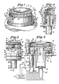
- FIG. 10 is a sectional view taken along the line 10-10 of FIG. 9;
- FIG. 11 is a sectional view taken along the line 11-11 of FIG. 9;
- FIG. 12 is a sectional view taken along the line 12-12 of FIG. 9;
- FIG. 13 is a side elevational view partially broken away to show interior details of the first alternative burner assembly of FIG. 9 as modified with a suspension mounting arrangement;
- FIG. 14 is a sectional view taken along the line 14-14 of FIG. 13;
- FIG. 15 is a sectional view taken along the line 15-15 of FIG. 13;
- FIG. 16 is a side elevational view partially broken away to show interior details of a second alternative burner assembly constructed in accordance with the invention with portions of a gas range top and a cooking grate;
- FIG. 17 is a sectional view taken along the line 17-17 of FIG. 16;
- FIG. 18 is a sectional view taken along the line 18-18 of FIG. 16;
- FIG. 19 is a sectional view taken along the line 19-19 of FIG. 18;
- FIG. 20 is a sectional view taken along the line 17-17 of FIG. 19;
- FIG. 21 is a sectional view taken along the line 21-21 of FIG. 19; and
- FlG. 22 is a sectional view taken along the line 22-22 of FIG. 19;
- FIG. 23 is a side elevational view partially broken away to show interior details of a third alternative burner assembly constructed in accordance with the invention with portions of a gas range top and a cooking grate;
- FIG. 24 is a fragmentary sectional view taken along the line 24-24 of FIG. 23;
- FIG. 25 is a fragmentary sectional view illustrating an alternative mounting arrangement of the burner assembly of FIG. 23; and
- FIG. 26 is a fragmentary sectional view taken along the line 26-26 of FIG. 23;
- FIGS. 27, 28 and 29 are fragmentary sectional views similar to FIG. 26 showing further alternative connection arrangements of the burner assembly of FIG. 23; and
- FIG. 30 is a fragmentary perspective view illustrating a stationary base assembly of the third alternative burner assembly of FIG. 23.
- Referring to FIGS. 1, 2, and 6, there is shown a gas burner assembly constructed in accordance with the principles of the present invention and designated as a whole by the
reference numeral 10. A portion of a range top orcooking top 12 is shown with theburner assembly 10. Theburner assembly 10 includes a detachable burner cap assembly designated as 14 and a stationary base assembly des ignated as 16. A spark electrode assembly designated as 18 is included with theburner cap assembly 14 for spark ignition. - An
ignition circuit 20 provides an electrical ground potential to aburner cap 22 and selectively provides a high voltage potential to aspark electrode 24 of thecap assembly 14 causing ignition sparks to be produced. Theignition circuit 20 is under the control of a valve switch associated with a burner valve (not shown) that controls the fuel rates to theburner assembly 10 from an off condition to a wide range of gas flow rates. Theelectrode 24 functions as a flame sensing probe during normal burner operation of theburner assembly 10. Theignition circuit 20 may be generally of the character disclosed in the before mention U. S. Patent No. 4,626,196, hereby incorporated by reference. It should be understood that other types of ignition circuits may be used to provide spark ignition at theburner assembly 10. - As its component parts, the
burner cap assembly 14 includes theburner cap 22, abottom plate 26 and thespark electrode assembly 18. Theburner cap 22 and thebottom plate 26 are formed of electrically conductive material, such as stamped sheet metal of a #3003 aluminum alloy. Theburner cap 22 and thebottom plate 26 are electrically connected with therange top 12 to electrical ground so that a separate ground connection and an insulative spacer member are not required. - In general, the detachable
burner cap assembly 14 can be removed from thestationary base assembly 16, for example, for cleaning in an automatic dishwasher or in a self-cleaning oven. As described below, theburner cap assembly 14 is arranged as a modular unit to prevent disassembly of its component parts by the user so that problems resulting from possible misassembly or parts being displaced are avoided. - As shown in FIG. 2, the detachable
burner cap assembly 14 includes thebottom plate 26 press fit or other wise securely attached within alower portion 28 of the a generally cylindricalburner cap body 22 defining aburner fuel chamber 30. Thebottom plate 26 includes a gas inlet 32 (FIG. 6) for supplying primary air-gas fuel mixture to theburner fuel chamber 30 from thestationary base assembly 16. Fuel flows from thechamber 30 through a plurality ofmain burner ports 34 and anignition port 36 formed in a recessedportion 38 below atop wall 39 of theburner body 22. Secondary air for combustion at theignition port 36 and theburner ports 34 flows from above therange top 12 rather than from an internal burner box location. - An electrically insulative support member designated as 40 of the
spark electrode assembly 18 positions thespark electrode 24 for reliable and repeatable ignition throughout the entire range of gas flow rates for theburner assembly 10. - As best seen in FIG. 5, the
insulative support member 40 has a centeringtapered nose portion 40A, anintermediate body portion 40B slideably received within the ignition port 36 (FIGS. 1 and 2) and arear body portion 40C positioning thenose portion 40A by providing a stop against the insideburner wall portion 38. Theinsulative support member 40 has a generally centrally disposedaperture 42 extending from thenose portion 40A to therear body portion 40C for receiving thespark ignition electrode 24. Thespark ignition electrode 24 is offset or L-shaped extending from thechamber 30 through thesupport member aperture 42 outside theburner body 22 and downwardly to thebase assembly 16.Aperture 42 is similarly L-shaped to accommodate thespark ignition electrode 24. - An
ignition gas region 44 is defined by thesupport member 40 in cooperation with theignition port 36.Ignition port 36 is circular and has a diameter generally coinciding with theintermediate body portion 40B of thesupport member 40. As shown in FIGS. 3 and 5, a pair of generally U-shaped undercutgrooves 46 are formed longitudinally along the outer periphery of thesupport member 40. When fuel is supplied to theburner assembly 10, ignition gas flows fromchamber 30 through thegrooves 46 to theignition region 44 spaced between thespark electrode 24 and the burnertop wall 39 and theburner body 28. - As shown in FIGS. 2, 4, and 6, a second electrically
insulative support member 48 of thespark electrode assembly 18 receives and isolates theelectrode 24 from theburner body 22 and thebottom plate 26. Theinsulative support member 48 has a centeringtapered nose portion 48A, anintermediate body portion 48B and anupper body portion 48C. Theintermediate body portion 48B of theinsulative support member 48 is press fit or otherwise securely attached within a generallycircular sleeve 50 of thebase plate 26 with theupper body portion 40C providing a stop against thebase plate 26. -
Insulative support members Spark ignition electrode 24 is an integral member formed of electrically conductive material, such as #310 stainless steel, having sufficient strength and stiffness needed to facilitate assembly of theburner cap 22 with thespark electrode assembly 18. - Assembly of the
burner cap assembly 14 is simply provided by placing thefirst support member 40 with thespark electrode 24 positioned within itsaperture 42 in theignition port 36 and then attaching thebase plate 26 with thesecond support member 48 secured within itssleeve 50 aligned for receiving thespark electrode 24. Then aterminal blade 52 is attached to thespark electrode 24 that in assembled relation extends within thestationary base assembly 16. - Electrical connection to the
spark electrode 24 and theburner body 22 is made in any conventional fashion. In FIG. 2, a pair ofconductors ignition circuit 20 to provide the high voltage connection to thespark electrode 24 via the termi nalblade 52 and the ground connection to theburner cap 22 through therange top 12. - As its major components, the
stationary base assembly 16 includes ahigh voltage receptacle 58 and a venturi designated as 60.Venturi 60 is positioned around a gas inlet fitting 62 that is connected to anair shutter assembly 64 for supplying the mixture of gas and primary air to theburner cap assembly 14 through theventuri 60. Frictional interengagement of theburner cap assembly 14 is provided with thebase assembly 16.Venturi 60 supplies primary air-gas mixture to the detachableburner cap assembly 14 through a centeringprojection 66 carrying asnap ring 68 clinched by theinlet 32 of thebase plate 26 in assembled relation. As seen in FIG. 6, an upstanding flange orwall portion 70 includes a pair ofapertures 70A. Theflanged portion 70 is secured to therange top 12 by a pair offasteners 71 received through theapertures 70A with one shown in FIG. 2. Thefasteners 71 provide an effective electrical ground connection between therange top 12 and theventuri 60 and through thebottom plate 26 to theburner cap body 22. Agasket 72 is sandwiched between theflanged portion 70 and range top 12 to provide an effective liquid seal. In general outline, theflanged portion 70 is annular and has an outside diameter slightly smaller than the inside diameter of theburner cap 22. Theinsulative support member 48 is received through anopening 74 separated from theventuri gas supply 66 in theflanged portion 70. - As shown in FIG. 1, the
burner assembly 10 makes possible a simple and easily cleaned range top or cooking top configuration. Thestationary base assembly 16 is received in anopening 12A of therange top 12 bounded by theflanged portion 70 around which theburner cap 22 rests. Therange top 12 is otherwise imperforate and includes no openings or spaces around theburner assembly 10 where contamination such as spillover from a cooking vessel can enter the region below therange top 12. - Referring now to FIGS. 7 and 8, an alternative arrangement of a spark electrode assembly 78 is shown. In the alternative assembly 78, an insulative support member 80 is formed without channels such as the
undercut grooves 46 in theinsulative support member 40. Instead a pair ofscallops 82 is configured in the periphery of theignition port 84 to define the ignition gas pathway. While thescallops 82 are shown extending generally horizontally, vertically arranged cutouts may be preferable to define the ignition gas pathway between theelectrode 24 and thewalls burner cap body 22. It should be understood that various other configured ignition ports and/or insulative support members could be employed to define the ignition gas pathway. - Referring now to FIGS. 9, 10, 11 and 12, there is shown a first alternative gas burner assembly constructed in accordance with the principles of the present invention and designated as a whole by the
reference numeral 110. Theburner assembly 110 includes a detachableburner cap assembly 114 including aspark electrode assembly 118 and a stationary base assembly designated as 116. Theburner assembly 110 is shown mounted on a recessedplanar portion 111 of a range top or cooking top 112 with an associatedcooking grate 113. - Optimum heat transfer and combustion operations are facillated by providing a vent space V between the range
top surface 112 and the top ofgrate 113 in a range between 1 and 1.35 inches and a grate space G between the burner cap top surface and the top of grate in a range between 0.6 and 0.7 inches. A depth of the recessedportion 111 is determined by the height H of the burner cap. For example, with a burner cap height H of 1.0 inch, the recessed portion has a depth of 0.25 inches to provide a vent space V of 1.35 inches and a grate space of 0.6 inches. - In the
bas burner assembly 110, the detachableburner cap assembly 114 and thespark electrode assembly 118 are substantially similar to theburner cap assembly 14 and thespark electrode assembly 18. The recessedrange top 111 is a planar surface eliminating the pedestal portion of therange top 12 as shown in FIGS. 1, 2 and 6. - As its major components, the
stationary base assembly 116 includes ahigh voltage receptacle 158 operatively associated with aspark electrode 124 of thespark electrode assembly 118, a mixing orventuri tube 160 for supplying a primary air-gas fuel mixture to theburner cap assembly 114, a gas inlet support member designated as 162 for connection with a gas supply line and for supporting thebase assembly 116 in a fixed position within the gas range and an air shutter assembly designated as 164 for entraining primary air in theventuri tube 160. Thestationary base assembly 116 is adapted for accurately aligning and positioning thehigh voltage receptacle 158 and thegas mixing member 160 with theburner cap assembly 114. - An upstanding flange or
wall portion 170 of theventuri 160 illustrated in FIGS. 9 and 10 is fixedly secured to the gas rangetop surface 111 by a pair offasteners 171 received through a pair of recessedapertures 170A in theflange 170 and a corresponding pair of holes 111A in thetop surface 111. An opening 111b is punched or formed in the rangetop surface 111 configured for receiving and positioning theventuri tube 160 and aninsulative support member 148 surrounding thespark electrode 124. Alower body portion 128 of aburner cap body 122 overlies theflange 170 and agasket 172 is sandwiched between theflange 170 and range top 111 configured for avoiding spillover from a cooking vessel entering the region below the range top. Theinsulative support member 148 is received through anopening 174 in theflange 170 separated from a venturigas supply outlet 166. - As best seen in FIGS. 9 and 11, the gas
inlet support member 162 is fixedly secured to a burner boxbottom wall 186 that includes anelongated slot 186A for receiving a downwardly extendingledge portion 187 ofmember 162 and anaperture 186B for receiving afastener 188 extending through an alignedaperture 189 in thesupport member 162.Slot 186A andhole 186B are punched or otherwise formed in the burner boxbottom wall 186 accurately located relative to the openings 111A and 111b in the rangetop surface 111 for securing thebase assembly 116 in fixed position with the gas range and theburner cap assembly 114 including thespark electrode assembly 118. - The gas
inlet support member 162 includes agas passageway 190 having a tapered inlet threaded to receive a fitting 192 which receives a gas supply conduit or tube (not shown) and terminates in anoutlet orifice 194 of an orifice fitting 196 for supplying gas to theventuri tube 160. - Referring to FIG. 12, a
central opening 164A is defined by a pair ofshutter members shutter assembly 164 for centering theoutlet orifice 194 within theventuri tube 160.Shutter members openings 164B around the inside circumference of theventuri tube 160.Shutter member 198 is fixedly secured to theventuri tube 160, such as by staking.Shutter member 200 is adjustably carried by thestationary shutter member 198 for controlling theopenings 164B including a pair ofopposed tab members 202 bent over theshutter member 198. - Referring again to FIGS. 9 and 11, the gas
inlet support member 162 includes achannel 204 having a pair of opposed recessedslots 205 configured for receiving a radially extending rectangular flanged portion orledge 206 formed at the lower end of aninsulative body housing 207 of thehigh voltage receptacle 158. Thehigh voltage receptacle 158 includes a conventional spring terminal (not shown) accurately positioned for mating engagement with aterminal blade 152 attached to thespark electrode 124. A high voltage/temperature conductor 208 coupled to thespark electrode 124 extends through thechannel 204 for connection with the ignition circuit. - Referring now to FIGS. 13, 14 and 15, an alternative suspension mounting arrangement is shown for the
gas burner assembly 110 eliminating the support engagement with theburner box bottom 186. A generally U-shapedstrap support member 185 supports thestationary base assembly 116 in fixed position within the gas range for detachable mating engagement with theburner cap assembly 114.Support member 185 is a unitary member of metal, such as aluminum, stamped and formed to define the U-shape. As best seen in FIGS. 13 and 14, theupstanding flange 170 of theventuri 160 and the rangetop surface 111 are modified to include anadditional aperture 170C and 111C for receiving athird fastener 171 and a pair ofalternative apertures 170D and111D replacing apertures 170A and 111A for receivingfasteners 171 that are aligned with a pair ofapertures 185A defined in upper arm portions of thesupport member 185 extending adjacent and below the rangetop surface 111. An aperture 185B is defined in a lower bottom wall of theU-shaped support member 185 aligned withaperture 189 of the gasinlet support member 162 for receiving thefastener 188 inserted upwardly through the aligned apertures. - Referring now to FIGS. 16-22, there is shown a second alternative gas burner assembly in accordance with the present invention designated as 210 and mounted on a recessed
planar portion 211 of a range top or cooking top 212 with an associatedcooking grate 213. Theburner assembly 210 includes a detachable burner cap assembly designated as 214 including a spark electrode assembly designated as 218 and a preferred stationary base assembly designated as 216. In thegas burner assembly 210, abottom plate member 226 is configured to provide a reduced height for the detachableburner cap assembly 214. A separate venturi member such asventuri 60 of FIGS. 1-8 orventuri 160 of FIGS. 9-15 has been eliminated in the preferredstationary base assembly 216 by an integrally formed upper venturi orgas mixing portion 260 of a gasinlet support member 262. Accurate positioning of a high voltage recep tacle 258 is provided by aclip bracket 286 secured to the gasinlet support member 262. - Referring first to FIG. 17, an alternative, preferred
spark electrode assembly 218 including a generally D-shapedignition port 236 and afirst support member 240 surrounding aspark electrode 224. Aflat wall portion 237 of theignition port 236 is located proximate to aburner body 228. Anignition gas region 244 is defined bysupport member 240 in cooperation with theignition port 236 spaced between thespark electrode 224 and a burnertop wall 239 and aburner body sidewall 228. A lower ignitiongas pathway portion 244A is smaller than an upper ignitiongas pathway portion 244B and provides improved flame sensing operation with the centrally disposedspark electrode 224. - As best seen in FIGS. 18 and 19, a
bottom plate 226 of theburner cap assembly 214 includes a centrally disposedgas inlet 232 for receiving a primary air-gas supply. A secondinsulative support member 248 carrying asnap ring 249 is clinched within anopening 250 in thebottom plate 226 spaced apart from thegas inlet 232. Acentral passageway 248A in the secondinsulative support member 248 receives thespark electrode 224. The secondinsulative support member 248 includes a main body portion 248B and an enlargedupper body portion 248C seated within atapered entrance 251 of thebottom plate opening 250. As illustrated best seen in FIG. 21, theinsulative support member 248 is accurately positioned withinaperture 250 and then is fixedly secured to thebottom plate 226, such as by staking at a plurality oflocations 226A on the lower surface of thebottom plate 226. Aterminal blade 252 attached to thespark electrode 224 is thereby maintained accurately positioned below therange top 211 in theburner assembly 210. - An
air receiving opening 260A is defined laterally in theventuri portion 260 for receiving primary air. Anair shutter member 264 is axially slidably disposed around theventuri portion 260 for adjusting theopening 260A. Theair shutter member 264 is a unitary member stamped and formed of metal, such as aluminum, configured generally corresponding to the shape of theventuri portion 260. A pair ofspring portions 264A near the opposite ends of theshutter member 264 frictionally secure theshutter member 264 with theventuri portion 260. - Primary air-gas is supplied to the
burner cap assembly 214 through an upper,circular projection 266 of the integrally formedventuri portion 260 extending above an upstandingflanged portion 270 of the gasinlet support member 262. Centeringprojection 266 carries asnap ring 268 clinced by theinlet 232 providing mechanical and electrical ground connection with theburner cap assembly 214. The upstandingflanged portion 270 includes a pair of recessedapertures 270A for receiving a pair offasteners 271 and anaperture 274 aligned withbase plate aperture 250 for receiving the secondinsulative support member 248. Referring to FIG. 18, the recessed rangetop portion 211 includes a pair ofapertures 211A aligned with theflange apertures 270A and anelongated aperture 211B shaped for receiving the upper, generallyrectangular venturi portion 260 and the generally circular main body portion 248B of theinsulative support member 248. - Referring to FIGS. 18, 19, 20 and 22, the
clip bracket 286 is secured to the gasinlet support member 262 by afastener 288 received upwardly through anaperture 286A in theclip bracket 286 and an aligned aperture 289 in thesupport member 262. A downwardly dependingprotuberance 287 of thesupport member 262 is received in a corresponding notch 286B within thebracket 286 for accurately aligning thehigh voltage receptacle 258. Theclip bracket 286 includes a pair oflegs 290 spaced apart to define apassageway 304 for receiving aninsulative body housing 307 of thehigh voltage receptacle 258. The spaced apartlegs 290 are formed to define achannel 305 configured for receiving a radially extendingrectangular ledge portion 306 formed at the lower end of thehousing 307 and accurately positioning a conventional spring terminal (not shown) contained in thehousing 307 for mating engagement with theterminal blade 252. A high voltage/temperature conductor 308 extends between the lower portion oflegs 290 for connection with the ignition circuit. The gasinlet support member 262 includes agas passageway 290 having a tapered inlet threaded to receive agas supply fitting 292 and terminates in anoutlet orifice 294 of an orifice fitting 296 for supplying gas to theventuri mixing portion 260. - Both the
air shutter member 264 and theclip bracket 286 can be stamped and formed of metal, such as aluminum. The gasinlet support member 262 preferably is formed by metal casting, such as of #380 aluminum. - Referring now to FIG. 23, there is shown a third alternative gas burner assembly in accordance with the present invention designated as 310 mounted on a recessed
pedestal portion 311 of a range top or cooking top 312 with an associatedcooking grate 313. Theburner assembly 310 includes a detachable burner cap assembly designated as 314 including a spark electrode assembly designated as 318 and a stationary base assembly designated as 316. In theburner assembly 310, theburner cap assembly 314 and thebase assembly 316 are modified to facillitate removal of the cooking top 312 to provide access to thebase assembly 316 for repair or adjustment. - Referring also to FIG. 24, a gas
inlet support member 362 of thestationary base assembly 316 is similar to thesupport member 262 of of FIGS. 16-22 modified to include a pair ofopposed ears 410, each defining anaperture 412 for receiving afastener 414, such as a shoulder screw for securing thesupport member 362 to a gasburner box bottom 416.Shoulder screws 414 facillate use of a standardsized support member 362 for various spaced dimensions of theburner box bottom 416 below thepedestal portion 311. - Referring to FIG. 25, an alternative mounting arrangement for the
stationary base assembly 316 is shown to accommodate for larger spaced dimensions between theburner box bottom 412 and thepedestal portion 311 further including a mountingbracket 418 secured to thesupport member 362 and a pair offasteners 420 for securing thebracket 418 with theburner box bottom 416. -
Burner cap assembly 314 is illustrated in more detail with a gas outlet 366 of thestationary base assembly 316 in FIG. 26. Abase plate 326 includes an outside wall or peripheral plate edge having an indexed or steppedshoulder 327 for frictional engagement with a correspondingdeformed portion 329 of theburner cap body 328 adapted for maintaining firm frictional engagement of thebase plate 326 and theburner cap body 328 substantially unaffected by thermal cycling of theburner assembly 310. A taperedlower portion 331 of the generally cylindricalburner cap body 328 overlies an upper part of the pedestal rangetop surface portion 311. - An upstanding
flanged portion 370 of aventuri tube portion 360 is positioned inside the pedestal rangetop surface portion 311 with agasket 372 sandwiched between theflange 370 and the bottom surface ofpedestal portion 311. A pair of taperedapertures 311A defined in the pedestal rangetop surface portion 311 are aligned with a pair ofapertures 370A in theflange 370 for receiving a pair offasteners 371. - A centrally located primary air-
gas receiving inlet 332 of thebase plate 326 includes an eyelet or ring member 333 for receiving a venturi outlet projection 366 carrying asnap ring 368. Ring member 333 and thesnap ring 368 are clinced between the venturi outlet projection 366 and thebase plate inlet 332. Ring member 333 is formed of metal, such as stainless steel or a nickel brass alloy to avoid corrosive interaction between the projection 366 and thebase plate inlet 332. The venturi outlet projection 366 carrying thesnap ring 368 is received through a centrally located rangetop aperture 311B. - As shown in FIG. 30, an
insulative support member 348 surrounding aspark electrode 324 of thespark ignition assembly 318 is received through a range top aperture 311C spaced from therange top aperture 311B and an alignedaperture 374 in thebase plate 326. - FIGS. 27, 28 and 29 are fragmentary sectional views similar to FIG. 26 illustrating alternative connection arrangements between the
burner cap assembly 314 and thestationary base assembly 316 of theburner assembly 310. Referring first to FIG. 27, the venturi outlet projection 366 carrying asnap ring 368 is modified for carrying asecond snap ring 422 axially spaced below thesnap ring 368. Theinlet 332 ofbase plate 326 includes asidewall 424 having a upper wall portion or shoulder 426 and a lower wall portion orshoulder 428 carrying a correspondingly shapedeyelet 430. Frictional interengagement between theburner cap assembly 314 and thestationary base assembly 316 is provided with theshoulders 426 and 428 positioned relative to the snap rings 368 and 422, as shown. - Referring to FIGS. 28, 29 and 30, a venturi outlet projection 366 includes a recessed
portion 432 for carrying aring member 434.Ring member 434 is formed of metal, such as stainless steel or a nickel brass alloy to avoid corrosive interaction between the projection 366 and thebase plate inlet 332.Ring member 434 is formed with a toroidal surface designated as 436 for frictional engagement with theinlet 332 ofbase plate 326. In FIG. 28, thebase plate inlet 332 includes aflat sidewall 438 defined between a upper toroidal surface 440 and a lowertoroidal surface 442 carrying a correspondingly shapedeyelet 444. Thetoroidal surface 436 ofring member 434 engages theflat sidewall 438. In FIG. 29, thebase plate inlet 332 is defined by atoroidal surface 446 carrying a correspondingly shapedeyelet 448 urged downwardly by thetoroidal surface 436 ofring member 434. - Although the present invention has been described in connection with details of the preferred embodiments, many alterations and modifications may be made without departing from the invention. Accordingly, it is intended that all such alterations and modifications be considered as within the spirit and scope of the invention as defined in the appended claims.
Claims (10)
a detachable burner cap assembly (114 or 214 or 314) including an electrically conductive burner cap body (122 or 222 or 322) including a sidewall (128 or 228 or 328), a plurality of burner ports (134 or 234 or 334) and an ignition port (138 or 238 or 338) formed in said burner body sidewall (136 or 236 or 336) and gas inlet means (132 or 232 or 332) for receiving primary air-gas fuel mixture;
an electrically insulative support member (140 or 240 or 340) extending through said ignition port (136 or 236 or 336) having an electrode receiving aperture (142 or 242 or 342), said support member (140 or 240 or 340) and said ignition port (136 or 236 or 336) cooperating to define an ignition gas pathway (144 or 244 or 344); and
a spark electrode (124 or 224 or 324) extending through said support member aperture (142 or 242 or 342) and including a portion extending though the ignition port (136 or 236 or 336) surrounded by said insulative support member (140 or 240 or 340); and
a stationary base assembly (116 or 216 or 316) including an air-gas mixing member (160 or 260 or 360) defining an aperture (164B or 260A or 360A) for receiving primary air and outlet means (166 or 266 or 366) for supplying a primary air-gas mixture and for providing an electrical ground potential to the burner cap assembly;
a high voltage receptacle (158 or 258 or 358) operatively associated with said spark electrode (124 or 224 or 324) for providing an electrical high voltage potential to said spark electrode (124 or 224 or 324); and
support means (162, 186, 188, or 262, 286, 288 or 410 or 418, 414, 416) for securing said base assembly (116 or 216 or 316) with the gas range.
Priority Applications (1)
| Application Number | Priority Date | Filing Date | Title |
|---|---|---|---|
| AT89122359T ATE95599T1 (en) | 1988-12-06 | 1989-12-05 | GAS BURNER WITH BUILT-IN SPARK IGNITION. |
Applications Claiming Priority (2)
| Application Number | Priority Date | Filing Date | Title |
|---|---|---|---|
| US280664 | 1988-12-06 | ||
| US07/280,664 US4846671A (en) | 1988-03-09 | 1988-12-06 | Integral spark ignited gas burner assembly |
Publications (2)
| Publication Number | Publication Date |
|---|---|
| EP0372462A1 true EP0372462A1 (en) | 1990-06-13 |
| EP0372462B1 EP0372462B1 (en) | 1993-10-06 |
Family
ID=23074064
Family Applications (1)
| Application Number | Title | Priority Date | Filing Date |
|---|---|---|---|
| EP89122359A Expired - Lifetime EP0372462B1 (en) | 1988-12-06 | 1989-12-05 | Integral spark ignited gas burner assembly |
Country Status (5)
| Country | Link |
|---|---|
| US (1) | US4846671A (en) |
| EP (1) | EP0372462B1 (en) |
| AT (1) | ATE95599T1 (en) |
| DE (1) | DE68909754T2 (en) |
| MX (1) | MX172503B (en) |
Cited By (3)
| Publication number | Priority date | Publication date | Assignee | Title |
|---|---|---|---|---|
| ES2063663A2 (en) * | 1992-10-22 | 1995-01-01 | Fagor S Coop Ltda | Extra-flat gas burner with safety device |
| US6951997B2 (en) | 2002-07-26 | 2005-10-04 | Ark-Les Corporation | Control of a cooktop heating element |
| US7420142B2 (en) | 2002-07-26 | 2008-09-02 | Illinois Tool Works, Inc | Power control module for electrical appliances |
Families Citing this family (57)
| Publication number | Priority date | Publication date | Assignee | Title |
|---|---|---|---|---|
| US5133334A (en) * | 1989-12-12 | 1992-07-28 | Robertshaw Controls Company | Burner construction and method of making the same |
| US5002038A (en) * | 1989-12-12 | 1991-03-26 | Robert Shaw Controls Company | Burner construction and method of making the same |
| US5085202A (en) * | 1989-12-12 | 1992-02-04 | Robertshaw Controls Company | Burner construction and method of making the same |
| US5040970A (en) * | 1990-04-12 | 1991-08-20 | Robertshaw Controls Company | Burner construction and method of making the same |
| US5083915A (en) * | 1990-04-12 | 1992-01-28 | Robertshaw Controls Company | Burner construction and method of making the same |
| US5186158A (en) * | 1990-08-23 | 1993-02-16 | Lincoln Brass Works, Inc. | Gas burner |
| US5266026A (en) * | 1990-10-17 | 1993-11-30 | Robertshaw Controls Company | Burner construction and method of making the same |
| US5152276A (en) * | 1990-12-27 | 1992-10-06 | Maytag Corporation | Sealed gas burner assembly |
| US5149262A (en) * | 1991-07-19 | 1992-09-22 | Robertshaw Controls Company | Burner construction, igniter assembly therefor |
| US5160255A (en) * | 1991-09-13 | 1992-11-03 | Robertshaw Controls Company | Burner construction and igniter assembly therefor |
| US5112218A (en) * | 1991-09-13 | 1992-05-12 | Robertshaw Controls Company | Burner construction, igniter assembly therefor and methods of making the same |
| US5125390A (en) * | 1991-10-31 | 1992-06-30 | Robertshaw Controls Company | Cooking apparatus, burner construction therefor and methods of making the same |
| US5267849A (en) * | 1992-01-13 | 1993-12-07 | Eaton Corporation | Spark igniting a fuel burner |
| US5391076A (en) * | 1993-03-05 | 1995-02-21 | Home; William | Gas burner for outdoor barbecuing device |
| US5397234A (en) * | 1993-11-15 | 1995-03-14 | Harper-Wyman Company | Gas stove top burner assembly |
| US5468145A (en) * | 1994-01-24 | 1995-11-21 | Lincoln Brass Works, Inc. | Sealed gas burner assembly |
| US5498154A (en) * | 1994-04-22 | 1996-03-12 | Leland C. Scheu | Burner with over surface ignitor and high limit control |
| US5525771A (en) * | 1994-11-30 | 1996-06-11 | Harper-Wyman Company | Spark ignition switch and valve assembly for gas burners including external detent assembly |
| US5567148A (en) * | 1994-12-20 | 1996-10-22 | Eaton Corporation | Gaseous fuel burner assembly and method of connecting same |
| AT405566B (en) * | 1996-07-30 | 1999-09-27 | Electrovac | TEMPERATURE LIMITER WITH IGNITION ELEMENT |
| US5865615A (en) * | 1997-02-12 | 1999-02-02 | Lincoln Brass Works, Inc. | Sealed burner |
| US6067978A (en) * | 1997-08-07 | 2000-05-30 | Schlosser; Erich J. | Outdoor cooking apparatus with improved auxiliary gas burner |
| US5924860A (en) * | 1997-08-28 | 1999-07-20 | Harper-Wyman Company | Thickwall gas burner assembly |
| BR9803428A (en) * | 1997-09-15 | 2001-03-20 | Harper Wyman Co | Spark ignition electrode set for gas burner |
| AT405117B (en) * | 1997-11-07 | 1999-05-25 | Electrovac | TEMPERATURE LIMITER WITH SENSOR ELECTRODE |
| US6059479A (en) * | 1998-03-13 | 2000-05-09 | Ensign Ribbon Burners, Llc | Pop-out electrode assembly |
| US5911572A (en) * | 1998-07-17 | 1999-06-15 | Harper-Wyman Company | Spark ignition electrode assembly for gas stove top burner |
| US6253759B1 (en) * | 1999-08-13 | 2001-07-03 | Sunbeam Products, Inc. | Side burner for a grill |
| US6254381B1 (en) | 2000-05-31 | 2001-07-03 | Maytag Corporation | Sealed gas burner electrode assembly |
| CN101793393B (en) * | 2002-08-09 | 2012-09-05 | 杰富意钢铁株式会社 | Tubular flame burner and combustion control method |
| US6817353B2 (en) | 2003-04-10 | 2004-11-16 | Maytag Corporation | Front serviceable ignition system for a cooking appliance |
| US20060000467A1 (en) * | 2004-06-30 | 2006-01-05 | Hibshman Joell R Ii | Gas cooking burner with enhanced air entrainment and system and method incorporating same |
| US20060024632A1 (en) * | 2004-07-29 | 2006-02-02 | Sanchez Jairo E | Gas burner head with extra simmer, burner base assembly and combination thereof |
| ITPD20070363A1 (en) * | 2007-11-06 | 2009-05-07 | Sit La Precisa Spa | BURNER, IN PARTICULAR GAS BURNER WITH PRE-MIXING |
| EP2105662B1 (en) * | 2008-03-25 | 2012-07-11 | Electrolux Home Products Corporation N.V. | Cooking top with improved gas top burner |
| SI2359061T1 (en) * | 2008-12-12 | 2018-12-31 | Sabaf S.P.A. | Gas burner for domestic cookers |
| US10690351B2 (en) * | 2009-02-10 | 2020-06-23 | Bsh Home Appliances Corporation | Home cooking appliance having a pedestal burner |
| FR2951808B1 (en) * | 2009-10-22 | 2011-11-18 | Gdf Suez | RADIANT BURNER WITH INCREASED YIELD, AND METHOD FOR IMPROVING THE YIELD OF A RADIANT BURNER |
| CN201582887U (en) * | 2009-11-23 | 2010-09-15 | 惠而浦产品研发(深圳)有限公司 | Burner cap and cooking range |
| US20120282560A1 (en) * | 2011-05-05 | 2012-11-08 | General Electric Company | Offset igniter assembly |
| ES2555207B1 (en) * | 2014-06-25 | 2016-10-04 | Bsh Electrodomésticos España, S.A. | Gas cooking point and cooking |
| USD787041S1 (en) * | 2015-09-17 | 2017-05-16 | Whirlpool Corporation | Gas burner |
| US10837651B2 (en) | 2015-09-24 | 2020-11-17 | Whirlpool Corporation | Oven cavity connector for operating power accessory trays for cooking appliance |
| US11777190B2 (en) | 2015-12-29 | 2023-10-03 | Whirlpool Corporation | Appliance including an antenna using a portion of appliance as a ground plane |
| USD829502S1 (en) * | 2016-03-01 | 2018-10-02 | Meyer Intellectual Properties Limited | Induction burner |
| US10145568B2 (en) | 2016-06-27 | 2018-12-04 | Whirlpool Corporation | High efficiency high power inner flame burner |
| US10697641B2 (en) | 2016-12-19 | 2020-06-30 | Whirlpool Corporation | Orifice holder mounting system for gas cooktop |
| US10627113B2 (en) | 2016-12-29 | 2020-04-21 | Whirlpool Corporation | Distributed vertical flame burner |
| US10551056B2 (en) | 2017-02-23 | 2020-02-04 | Whirlpool Corporation | Burner base |
| US10451290B2 (en) | 2017-03-07 | 2019-10-22 | Whirlpool Corporation | Forced convection steam assembly |
| US10660162B2 (en) | 2017-03-16 | 2020-05-19 | Whirlpool Corporation | Power delivery system for an induction cooktop with multi-output inverters |
| US10969110B2 (en) * | 2017-05-16 | 2021-04-06 | Malcolm Gorst | Universal housing for a hot surface igniter |
| US11181282B2 (en) * | 2018-05-14 | 2021-11-23 | Furrion Property Holding Limited | Flat top gas range, a counter containing, and a vehicle containing |
| US10627116B2 (en) | 2018-06-26 | 2020-04-21 | Whirlpool Corporation | Ventilation system for cooking appliance |
| US10619862B2 (en) | 2018-06-28 | 2020-04-14 | Whirlpool Corporation | Frontal cooling towers for a ventilation system of a cooking appliance |
| US10837652B2 (en) | 2018-07-18 | 2020-11-17 | Whirlpool Corporation | Appliance secondary door |
| US11125440B2 (en) * | 2019-06-28 | 2021-09-21 | Midea Group Co., Ltd. | Igniter assembly for a gas cooking appliance |
Citations (6)
| Publication number | Priority date | Publication date | Assignee | Title |
|---|---|---|---|---|
| US2960980A (en) * | 1955-12-14 | 1960-11-22 | Selas Corp Of America | Stove burner |
| FR1421600A (en) * | 1964-11-06 | 1965-12-17 | Sourdillon Ets | Improvements to gas appliances such as stoves, stoves, washing machines, and others |
| GB1165841A (en) * | 1966-06-18 | 1969-10-01 | Welcker F | Electric-Spark Ignited Gas Burners |
| FR2393234A1 (en) * | 1977-06-03 | 1978-12-29 | Martinez Antoine | Burner for gas cooker - has peripheral recess in head connected by small dia. drillings to central chamber |
| FR2404803A1 (en) * | 1977-09-29 | 1979-04-27 | Sourdillon Sa | Burner for domestic gas cooker - has mixer tube below the head and downstream of metering jet |
| AT387647B (en) * | 1977-02-09 | 1989-02-27 | Elektra Bregenz Ag | BURNER SET |
Family Cites Families (7)
| Publication number | Priority date | Publication date | Assignee | Title |
|---|---|---|---|---|
| US1968978A (en) * | 1931-09-08 | 1934-08-07 | Gilbert E White | Gas fuel burner |
| GB1543618A (en) * | 1977-02-18 | 1979-04-04 | British Gas Corp | Gas burners |
| FR2408096A1 (en) * | 1977-11-02 | 1979-06-01 | Sourdillon Sa | Gas burner with electronic ignition - has electrode positioned in gas passage and surrounded by earthing sleeve around support material |
| NL7808145A (en) * | 1978-08-02 | 1980-02-05 | Pelgrim Bv | Gas cooker burner electric igniter - has one electrode connected to burner cover which is insulated from cup |
| FR2545196B1 (en) * | 1983-04-29 | 1985-08-16 | Gaz De France | BURNER FOR GAS FUELS WITH INCORPORATED IGNITION AND SAFETY SYSTEMS |
| US4626196A (en) * | 1985-09-23 | 1986-12-02 | Harper-Wyman Company | Spark ignited gas burner |
| US4810188A (en) * | 1988-03-09 | 1989-03-07 | Harper-Wyman Company | Spark ignited gas burner assembly |
-
1988
- 1988-12-06 US US07/280,664 patent/US4846671A/en not_active Expired - Lifetime
-
1989
- 1989-12-05 MX MX018581A patent/MX172503B/en unknown
- 1989-12-05 EP EP89122359A patent/EP0372462B1/en not_active Expired - Lifetime
- 1989-12-05 AT AT89122359T patent/ATE95599T1/en not_active IP Right Cessation
- 1989-12-05 DE DE89122359T patent/DE68909754T2/en not_active Expired - Fee Related
Patent Citations (6)
| Publication number | Priority date | Publication date | Assignee | Title |
|---|---|---|---|---|
| US2960980A (en) * | 1955-12-14 | 1960-11-22 | Selas Corp Of America | Stove burner |
| FR1421600A (en) * | 1964-11-06 | 1965-12-17 | Sourdillon Ets | Improvements to gas appliances such as stoves, stoves, washing machines, and others |
| GB1165841A (en) * | 1966-06-18 | 1969-10-01 | Welcker F | Electric-Spark Ignited Gas Burners |
| AT387647B (en) * | 1977-02-09 | 1989-02-27 | Elektra Bregenz Ag | BURNER SET |
| FR2393234A1 (en) * | 1977-06-03 | 1978-12-29 | Martinez Antoine | Burner for gas cooker - has peripheral recess in head connected by small dia. drillings to central chamber |
| FR2404803A1 (en) * | 1977-09-29 | 1979-04-27 | Sourdillon Sa | Burner for domestic gas cooker - has mixer tube below the head and downstream of metering jet |
Cited By (4)
| Publication number | Priority date | Publication date | Assignee | Title |
|---|---|---|---|---|
| ES2063663A2 (en) * | 1992-10-22 | 1995-01-01 | Fagor S Coop Ltda | Extra-flat gas burner with safety device |
| US6951997B2 (en) | 2002-07-26 | 2005-10-04 | Ark-Les Corporation | Control of a cooktop heating element |
| US7304274B2 (en) | 2002-07-26 | 2007-12-04 | Illinois Tool Works Inc. | Control of a cooktop heating element |
| US7420142B2 (en) | 2002-07-26 | 2008-09-02 | Illinois Tool Works, Inc | Power control module for electrical appliances |
Also Published As
| Publication number | Publication date |
|---|---|
| MX172503B (en) | 1993-12-17 |
| DE68909754D1 (en) | 1993-11-11 |
| US4846671A (en) | 1989-07-11 |
| EP0372462B1 (en) | 1993-10-06 |
| DE68909754T2 (en) | 1994-01-27 |
| ATE95599T1 (en) | 1993-10-15 |
Similar Documents
| Publication | Publication Date | Title |
|---|---|---|
| EP0372462A1 (en) | Integral spark ignited gas burner assembly | |
| EP0331815A2 (en) | Spark ignited gas burner assembly | |
| US5924860A (en) | Thickwall gas burner assembly | |
| EP0585226B1 (en) | Sealed gas burner assembly | |
| US5468145A (en) | Sealed gas burner assembly | |
| US5186158A (en) | Gas burner | |
| US6135764A (en) | Ribbon port burner for gas range | |
| PL190118B1 (en) | Gas burner for a gas range | |
| AU661068B2 (en) | Cooking apparatus, burner construction therefor and methods of making the same | |
| US4953534A (en) | Gas burner assembly of extra flat type | |
| EP0579157A1 (en) | Gas burner with a control thermocouple | |
| EP0234039A2 (en) | A gas burner | |
| CA2942596C (en) | Self-adjusting burner igniter for gas cooktops | |
| CN213901152U (en) | Burner with induction reliable ignition device | |
| CN220321297U (en) | Burner and combustion range | |
| CN219656134U (en) | Burner with a burner body | |
| CN214664391U (en) | Combustor and contain its cooking utensils | |
| CN211084059U (en) | Base frame for installing dry burning prevention structure and burner injection pipe | |
| CN218209703U (en) | Burner and gas cooker | |
| CN216010927U (en) | Ignition needle mounting structure and combustor | |
| JPH11264544A (en) | Structure of attaching accessory to burner for gas cooker | |
| JP2000283414A (en) | Mounting structure of burner accessory component to burner for gas cooking appliance | |
| JPH0141019Y2 (en) | ||
| JPH02101328A (en) | Portable gas burner | |
| EP1241411A1 (en) | Gas spark plug fastener and ignition gap ground |
Legal Events
| Date | Code | Title | Description |
|---|---|---|---|
| PUAI | Public reference made under article 153(3) epc to a published international application that has entered the european phase |
Free format text: ORIGINAL CODE: 0009012 |
|
| AK | Designated contracting states |
Kind code of ref document: A1 Designated state(s): AT BE CH DE ES FR GB GR IT LI LU NL SE |
|
| 17P | Request for examination filed |
Effective date: 19901206 |
|
| 17Q | First examination report despatched |
Effective date: 19910502 |
|
| GRAA | (expected) grant |
Free format text: ORIGINAL CODE: 0009210 |
|
| AK | Designated contracting states |
Kind code of ref document: B1 Designated state(s): AT BE CH DE ES FR GB GR IT LI LU NL SE |
|
| PG25 | Lapsed in a contracting state [announced via postgrant information from national office to epo] |
Ref country code: IT Free format text: LAPSE BECAUSE OF FAILURE TO SUBMIT A TRANSLATION OF THE DESCRIPTION OR TO PAY THE FEE WITHIN THE PRE;WARNING: LAPSES OF ITALIAN PATENTS WITH EFFECTIVE DATE BEFORE 2007 MAY HAVE OCCURRED AT ANY TIME BEFORE 2007. THE CORRECT EFFECTIVE DATE MAY BE DIFFERENT FROM THE ONE RECORDED.SCRIBED TIME-LIMIT Effective date: 19931006 Ref country code: NL Effective date: 19931006 Ref country code: LI Effective date: 19931006 Ref country code: AT Effective date: 19931006 Ref country code: SE Effective date: 19931006 Ref country code: GR Free format text: LAPSE BECAUSE OF FAILURE TO SUBMIT A TRANSLATION OF THE DESCRIPTION OR TO PAY THE FEE WITHIN THE PRESCRIBED TIME-LIMIT Effective date: 19931006 Ref country code: BE Effective date: 19931006 Ref country code: ES Free format text: THE PATENT HAS BEEN ANNULLED BY A DECISION OF A NATIONAL AUTHORITY Effective date: 19931006 Ref country code: CH Effective date: 19931006 |
|
| REF | Corresponds to: |
Ref document number: 95599 Country of ref document: AT Date of ref document: 19931015 Kind code of ref document: T |
|
| REF | Corresponds to: |
Ref document number: 68909754 Country of ref document: DE Date of ref document: 19931111 |
|
| ET | Fr: translation filed | ||
| PG25 | Lapsed in a contracting state [announced via postgrant information from national office to epo] |
Ref country code: LU Free format text: LAPSE BECAUSE OF NON-PAYMENT OF DUE FEES Effective date: 19931231 |
|
| REG | Reference to a national code |
Ref country code: CH Ref legal event code: PL |
|
| NLV1 | Nl: lapsed or annulled due to failure to fulfill the requirements of art. 29p and 29m of the patents act | ||
| PLBE | No opposition filed within time limit |
Free format text: ORIGINAL CODE: 0009261 |
|
| STAA | Information on the status of an ep patent application or granted ep patent |
Free format text: STATUS: NO OPPOSITION FILED WITHIN TIME LIMIT |
|
| 26N | No opposition filed | ||
| PGFP | Annual fee paid to national office [announced via postgrant information from national office to epo] |
Ref country code: GB Payment date: 19981110 Year of fee payment: 10 |
|
| PGFP | Annual fee paid to national office [announced via postgrant information from national office to epo] |
Ref country code: FR Payment date: 19981203 Year of fee payment: 10 |
|
| PGFP | Annual fee paid to national office [announced via postgrant information from national office to epo] |
Ref country code: DE Payment date: 19981230 Year of fee payment: 10 |
|
| PG25 | Lapsed in a contracting state [announced via postgrant information from national office to epo] |
Ref country code: GB Free format text: LAPSE BECAUSE OF NON-PAYMENT OF DUE FEES Effective date: 19991205 |
|
| GBPC | Gb: european patent ceased through non-payment of renewal fee |
Effective date: 19991205 |
|
| PG25 | Lapsed in a contracting state [announced via postgrant information from national office to epo] |
Ref country code: FR Free format text: LAPSE BECAUSE OF NON-PAYMENT OF DUE FEES Effective date: 20000831 |
|
| PG25 | Lapsed in a contracting state [announced via postgrant information from national office to epo] |
Ref country code: DE Free format text: LAPSE BECAUSE OF NON-PAYMENT OF DUE FEES Effective date: 20001003 |
|
| REG | Reference to a national code |
Ref country code: FR Ref legal event code: ST |