EP0371450A2 - Headstock-reciprocating-type automatic lathe and machining method using the same - Google Patents
Headstock-reciprocating-type automatic lathe and machining method using the same Download PDFInfo
- Publication number
- EP0371450A2 EP0371450A2 EP89121917A EP89121917A EP0371450A2 EP 0371450 A2 EP0371450 A2 EP 0371450A2 EP 89121917 A EP89121917 A EP 89121917A EP 89121917 A EP89121917 A EP 89121917A EP 0371450 A2 EP0371450 A2 EP 0371450A2
- Authority
- EP
- European Patent Office
- Prior art keywords
- machining
- headstock
- workpiece
- blank material
- axis
- Prior art date
- Legal status (The legal status is an assumption and is not a legal conclusion. Google has not performed a legal analysis and makes no representation as to the accuracy of the status listed.)
- Granted
Links
Images


Classifications
-
- B—PERFORMING OPERATIONS; TRANSPORTING
- B23—MACHINE TOOLS; METAL-WORKING NOT OTHERWISE PROVIDED FOR
- B23B—TURNING; BORING
- B23B3/00—General-purpose turning-machines or devices, e.g. centre lathes with feed rod and lead screw; Sets of turning-machines
- B23B3/30—Turning-machines with two or more working-spindles, e.g. in fixed arrangement
-
- B—PERFORMING OPERATIONS; TRANSPORTING
- B23—MACHINE TOOLS; METAL-WORKING NOT OTHERWISE PROVIDED FOR
- B23Q—DETAILS, COMPONENTS, OR ACCESSORIES FOR MACHINE TOOLS, e.g. ARRANGEMENTS FOR COPYING OR CONTROLLING; MACHINE TOOLS IN GENERAL CHARACTERISED BY THE CONSTRUCTION OF PARTICULAR DETAILS OR COMPONENTS; COMBINATIONS OR ASSOCIATIONS OF METAL-WORKING MACHINES, NOT DIRECTED TO A PARTICULAR RESULT
- B23Q39/00—Metal-working machines incorporating a plurality of sub-assemblies, each capable of performing a metal-working operation
- B23Q39/04—Metal-working machines incorporating a plurality of sub-assemblies, each capable of performing a metal-working operation the sub-assemblies being arranged to operate simultaneously at different stations, e.g. with an annular work-table moved in steps
- B23Q39/048—Metal-working machines incorporating a plurality of sub-assemblies, each capable of performing a metal-working operation the sub-assemblies being arranged to operate simultaneously at different stations, e.g. with an annular work-table moved in steps the work holder of a work station transfers directly its workpiece to the work holder of a following work station
-
- B—PERFORMING OPERATIONS; TRANSPORTING
- B23—MACHINE TOOLS; METAL-WORKING NOT OTHERWISE PROVIDED FOR
- B23B—TURNING; BORING
- B23B7/00—Automatic or semi-automatic turning-machines with a single working-spindle, e.g. controlled by cams; Equipment therefor; Features common to automatic and semi-automatic turning-machines with one or more working-spindles
- B23B7/02—Automatic or semi-automatic machines for turning of stock
- B23B7/06—Automatic or semi-automatic machines for turning of stock with sliding headstock
-
- B—PERFORMING OPERATIONS; TRANSPORTING
- B23—MACHINE TOOLS; METAL-WORKING NOT OTHERWISE PROVIDED FOR
- B23Q—DETAILS, COMPONENTS, OR ACCESSORIES FOR MACHINE TOOLS, e.g. ARRANGEMENTS FOR COPYING OR CONTROLLING; MACHINE TOOLS IN GENERAL CHARACTERISED BY THE CONSTRUCTION OF PARTICULAR DETAILS OR COMPONENTS; COMBINATIONS OR ASSOCIATIONS OF METAL-WORKING MACHINES, NOT DIRECTED TO A PARTICULAR RESULT
- B23Q1/00—Members which are comprised in the general build-up of a form of machine, particularly relatively large fixed members
- B23Q1/72—Auxiliary arrangements; Interconnections between auxiliary tables and movable machine elements
- B23Q1/76—Steadies; Rests
-
- Y—GENERAL TAGGING OF NEW TECHNOLOGICAL DEVELOPMENTS; GENERAL TAGGING OF CROSS-SECTIONAL TECHNOLOGIES SPANNING OVER SEVERAL SECTIONS OF THE IPC; TECHNICAL SUBJECTS COVERED BY FORMER USPC CROSS-REFERENCE ART COLLECTIONS [XRACs] AND DIGESTS
- Y10—TECHNICAL SUBJECTS COVERED BY FORMER USPC
- Y10T—TECHNICAL SUBJECTS COVERED BY FORMER US CLASSIFICATION
- Y10T82/00—Turning
- Y10T82/10—Process of turning
-
- Y—GENERAL TAGGING OF NEW TECHNOLOGICAL DEVELOPMENTS; GENERAL TAGGING OF CROSS-SECTIONAL TECHNOLOGIES SPANNING OVER SEVERAL SECTIONS OF THE IPC; TECHNICAL SUBJECTS COVERED BY FORMER USPC CROSS-REFERENCE ART COLLECTIONS [XRACs] AND DIGESTS
- Y10—TECHNICAL SUBJECTS COVERED BY FORMER USPC
- Y10T—TECHNICAL SUBJECTS COVERED BY FORMER US CLASSIFICATION
- Y10T82/00—Turning
- Y10T82/25—Lathe
- Y10T82/2524—Multiple
Definitions
- This invention relates to a headstock-reciprocating-type automatic lathe and a machining method using it, and more particularly to a workpiece supporting mechanism and method, for a headstock-receiprocating-type automatic lathe, which has first and second headstocks and is capable of performing front and rear machinings.
- automatic lathes are known in which the gripping of a workpiece, the cutting of the workpiece in multiple steps into a desired shape by using a plurality of cutting tools, and the discharging of the finished workpiece are performed in an almost fully automated fashion.
- this automatic lathe constitutes an essential part of a turning center or the like and is usually numerically controlled by a computer.
- a headstock-reciptorcating-type automatic lathe in which a headstock gripping the workpiece gives to the workpiece a driving rotation and slides on the bed along the machining axis, is most widely used as a relatively small-sized and precise machining unit.
- This type of automatic lathe is well known as a Swiss-type automatic. Yet in recent years, it has been realized to add a second headstock to perform a rear machining, in addition to a front machining to be performed by the first headstock.
- the second headstock grips the other end of the workpiece and gives a predetermined driving rotation to the workpiece to take the final machining, thus causing an expanded function of the Swiss-type automatic lathe.
- the second headstock is also slidable in the machining axis of the first headstock; as the second headstock takes the final machining and subsequently discharges the workpiece, the first headstock can stand by for the machining of the next blank material. This arrangement was accordingly very effective in shortening the entire cycle of process.
- this conventional double-headstock automatic lathe is to take a cutting on the end surface of the workpiece, as a rear machining, by the second headstock.
- This conventional lathe is used only for machining the end surface of the workpiece, which has been removed from the first headstock, to measure. That is, in the prior art, the second headstock plays as just an assistant to help the first headstock in taking the final stage of the machining of the workpiece.
- the second headstock also supports the workpiece at only one end thereof, the allowable length of the overhang part of the workpiece is about twice or triple the diameter of the supported portion of the workpiece to secure a highly precise machining against any lateral pressure.
- the range in which the rear machining can be performed was remarkably restricted.
- Another object of the invention is to provide a machining method using such an improved headstock-reciprocating-type automatic lathe.
- a headstock-reciprocating-type automatic lathe has an additional guide bush for intermediately guiding the workpiece near the working point of a cutting tool along the machining axis of the second headstock.
- the second headstock is slidable in a direction perpendicular to the machining axis of the first headstock and has a rear machining axis different from the machining axis of the first headstock.
- first and second headstocks may have a common machining axis.
- the second headstock is slidable on and along the machining axis of the first headstock.
- the length of the overhang part of the workpiece is adequately large so that the range to be shaped by the rear machining can be remarkably expanded to an extent substantially equal to the range of the front machining.
- the first headstock can take the front machining of the next blank material during the rear machining, thus reducing the entire machining time remarkably.
- the first machining and the rear machining can be performed at remotely spaced positions, thus eliminating the machining restrictions due to the interference of the cutting tools.
- the working points of the two headstocks are located at axially spaced positions, and the sliding motion in the direction perpendicular to the machining axis of the second headstock. Accordingly, it is possible to make the lathe simple in construction and also to reduce the machining time.
- lathe headstock-reciprocating-type automatic lathe
- a first headstock 14 is slidably movably carried on a base 12 fixed to a bed 10.
- the first headstock 14 is slidably movable on the base 12 in a direction of an arrow A along a first machining axis 100.
- the movement of the first headstock 14 is controlled by a servo motor 16 supported on the base 12. Consequently, though there is no detailed illustration in the drawings, under the control of a computer according to a predetermined machining program, the first headstock 14 grips a blank material, e.g., an elongated or continuous-length cylindrical rod, then moves the blank material to a working point of a cutting tool (described below), and rotates the blank material for machining. The headstock 14 can be moved along the first machining axis 100 by the servo motor 16.
- a blank material e.g., an elongated or continuous-length cylindrical rod
- a first tool post 20 and a second tool post 22 are reciprocatingly slidably carried on a base 18 fixed to the bed 10.
- the first and second tool posts 20, 22 are reciprocatingly movable on the base 18 perpendicularly to the first machining axis 100 as indicated by arrows B, C, respectively.
- a first turret 24 and a second turret 26 are rotatably supported on the first and second tool posts 20, 22, respectively.
- a first set of various cutting tools 32 and a second set of various cutting tools 34 are detachably supported via a pair of tool holders 28, 30, respectively, so that a desired machining can be performed.
- the working point of the workpiece is defined by the crossing point of the cutting axis 200 and the workpiece.
- the lathe is equipped with a first guide bush 36 fixed to a first guide bush holder 38 fixed to the base 18.
- the blank material is therefore intermediately guided near the working point by the first guide bush 36 so that a desired precise machining can be performed by the cutting tools 32, 34.
- a slide base 42 is reciprocatingly slidably carried on a base 40 fixed to the bed 10.
- the slide base 42 is reciprocatingly slidable in the direction of an arrow D along the first machining axis 100.
- a second headstock 44 is carried so as to be reciprocatingly slidable in the direction of an arrow E perpendicular to the first machining axis 100. Consequently, the second head stock 44 is movable optionally either along the first machining axis 100 or in the direction perpendicular to the first machining axis 100.
- a rear or second machining axis of the second headstock 44 is designated by 300.
- the second machining axis 300 is out of axial alignment with the first machining axis 100.
- the second headstock 44 grips the other end of the workpiece on the first machining axis 100 and then slides in the direction of an arrow E to take a desired rear machining along the second machining axis 300.
- a pair of servo motors 46, 48 are supported on the base 40 and the slide base 42 for moving the second headstock 44 in the optional direction of either the arrow D or the arrow E.
- the lathe is also equipped with a second guide bush 50 for intermediately guiding the workpiece near the working point while the rear machining is being performed along the second machining axis 300 by the second headstock 44.
- the second guide bush 50 is fixed to the bed 10 by a second guide bush holder 52.
- the guide bush 50 is disposed in axial alignment with the second machining axis 300, and can intermediately guide the workpiece near a second working point as the second headstock 44 grips the workpiece and slides it along the second machining axis 300, as shown in phantom lines in FIG. 1.
- the rear maching is performed by a rear cutting tool 54 detachably held by the second turret 26; the crossing point of a second cutting axis 400 and the workpiece defines the rear working point.
- the second headstock 44 supports the workpiece with a relatively large overhang thereof, e.g., if the extent of overhang is more than ten times the diameter of the gripped portion of the workpiece, it is possible to keep the workpiece in a proper posture against lateral pressure when the maching range is large, thus realizing a highly precise machining.
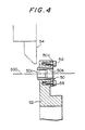
- FIG. 4 shows a preferred example of the second guide bush 50.
- the second guide bush 50 is firmly fastened to the second guide bush holder 52 by screws 56, 58 extending through a flange 50 of the second guide bush 50.
- the second guide bush 50 has a receiving taper surface 50b on the workpiece side and can guide the workpiece exactly onto a guide surface 50C of the second guide bush 50.
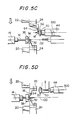
- FIGS. 5A through 5D show a cycle of progressive machining steps according to the first embodiment.
- FIG. 6A shows a workpiece machined by the front machining according to this embodiment
- FIG. 6B shows a workpiece machined by the front and rear machining.
- the front machining is performed as the first headstock 14 grips the blank material M and moves the same along the first machining axis 100.
- the front machining is carried out by the cutting tool 32 of the first turret 24.
- the thus machined workpiece is shown in FIG. 6A; substantially a half of the machining cycle is assigned to the front machining by the first headstock.
- the second headstock 44 stands by at a position remote from the working point along the first machining axis 100. Practically, however, the second headstock 44 is doing usually the rear maching during the front machining by the first headstock 14, as described below.
- the first headstock 14 moves the blank material M and the workpiece W forwardly along the first machining axis 100 and, meanwhile, the second headstock 44 advances to receive the other end of the workpiece W.
- the workpiece W is severed from the blank material M at the final stage of the front machining, immediately before which the second headstock 44 grips the other end of the workpiece W.
- the workpiece W on which the front machining has been completed and which is shown in FIG. 6A is assigned to the second headstock 44, whereupon the rear machining starts.
- a desired rear machining is performed by the rear cutting tool 54 as the second headstock 44 slides the workpiece W onto the second maching axis 300, and then the second guide bush 50 intermediately guides the workpiece W.
- the workpiece W projects or overhangs from the second headstock 44 to a relatively large extent.
- the practical rear machining is carried out as the workpiece W is intermediately guided near the working point by the second guide bush 50, a highly precise machining can be achieved even when any large lateral pressure is exerted on the workpiece W.
- the first headstock 14 already grips the next blank material M to take the front machining.
- the workpiece W completed with the front and rear machinings is pulled out from the second guide bush 50 by the second headstock 44 so that the workpiece may be discharged from the lathe.
- the workpiece W completed with the first and second machinings has been obtained as shown in FIG. 6B.
- the workpiece may be discharged by blowing air from the rear end of the second headstock 44, pushing out by a push rod via a cylinder unit or handling by a robot.
- the distance between the second guide bush 50 and the second headstock 44 must be more than the length of the workpiece to take out the workpiece from the second headstock 44.
- the second guide bush is used to support the other end of the workpiece so as to have an adequate overhang during the rear machining
- the workpiece such as in the form of a cylindrical rod can be shaped not only at its end surface but also its side peripheral surface, thus expanding the range of the rear machining to a remarkable extent.
- the moving ranges of the cutting tools and other members can be set to adequate largeness. Therefore complex machinings of both the front and rear parts of the workpiece can be achieved.
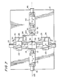
- FIGS. 7, 8 and 9 show a modified lathe according to a second embodiment of this invention. Parts similar to those of the first embodiment are designated by like reference numerals; their detailed description is omitted here for clarity.
- the second headstock 44 is slidable only along the first machining axis 100 and, unlike the first embodiment, is not slidable in a direction perpendicular to the first machining axis 100.
- the second guide bush 50 is located in axial alignment with the first machining axis 100, and is supported by the guide bush holder 52 fixed to the base 40.
- the lathe of this second embodiment is simple in construction. Further, since the second headstock is from any lateral sliding movement, it is possible to shorten the machining cycle to such extent.
- the second headstock 44 moves along the first machining axis to an adequate extent, as indicated by the arrow D.
- the workpiece can be supported at two points by the first guide bush 36 and the second guide bush 50 during the front machining, if necessary.
- FIGS. 10A through 10D show a cycle ofprogressivelysive machining steps according to the second embodiment.
- FIG. 10A shows the front machining step by the first headstock 14, during which the second headstock 44 is fully retracted to the right on the first machining axis 100.
- FIG. 10B shows the step in which the workpiece W is severed off the blank material M.
- the blank material M is advanced from the first headstock 14 adequately, whereupon the workpiece W is cut off by the cutting tool 54 as it is supported by the second guide bush 50.
- FIG. 10C shows the step in which the workpiece W severed off the blank material M is under the rear machining. At that time the blank material M is under the next front machining.
- FIG. 10D shows the step in which the workpiece W completed with the rear machining is being discharged as indicated by an arrow.
- the various members is returned from this position to the position of FIG. 10A ready for the next rear machining.
- the foregoing steps are repeated.
- Thus a shortened automatic machining cycle has been completed.
- FIG. 11 shows another modified lathe according to a third embodiment, in which the second headstock 44 is movable only along the first machining axis 100, and the second guide bush 50 is slidable in a direction perpendicular to the first machining axis 100, as indicated by an arrow F.
- the second guide bush 50 is retracted laterally from the first machining axis during the front machining, but can be located in alignment with the first machining axis 100 to perform a desired rear machining. Therefore, the lathe of this third embodiment is simple in construction. Further, easy and smooth movements of the cutting tools can be achieved within the machining range.
- FIG. 12 shows still another modified lathe according to a fourth embodiment.
- the second headstock 44 is slidable only on the first machining axis 100
- the second guide bush 50 is slidable perpendicularly to the first machining axis 100.
- the second guide bush 50 is substituted for the cutting tools carried by the second turret 26. Accordingly it is possible to achieve the function of this invention with simple construction.
- the front and rear machinings are carried out on the left and right ends, respectively, of the bed.
- the front and rear machinings may be performed on the first and second headstocks parallel to each other according to need.
- the workpiece completed with the front machining is gripped, whereupon the workpiece is reoriented and moved to the second headstock located adjacent to the first headstock so that the second machining can be performed by the second headstock.
- a plurality of second guide bushes different in diameter are arranged to meet with the shape of a workpiece.
- These second guide bushes may be optionally selectively used by a linear-drive index mechanism or a rotary index mechanism, or in combination thereof, which would cause an improved usefulness. Any combination of the foregoing changes and variations do not introduce new matter.
- the second guide bush is added to intermediately guide the workpiece during the rear machining, it is possible to take an adequately large overhang of the workpiece during the rear machining. Consequently a variety of kinds of machinings can be possible. Further the entire machining cycle can be divided into front and rear machinings, thus shortening the machining cycle to a minimum.
- the first and second headstocks are slidable along their respective machining axes, and the first headstock grips the blank material to take a front machining, whereupon the semi-machined blank material, i.e., a workpiece is transferred to the second headstock to take a rear machining.
- the lathe also has first and second guide bushes for intermediately guiding the workpiece near the working point while the workpiece is gripped by the first and second headstocks.
- the entire machining cycle can be divided into the front and rear machinings. Thus it is possible to shorten the machining cycle period.
Abstract
Description
- This invention relates to a headstock-reciprocating-type automatic lathe and a machining method using it, and more particularly to a workpiece supporting mechanism and method, for a headstock-receiprocating-type automatic lathe, which has first and second headstocks and is capable of performing front and rear machinings.
- Heretofore, automatic lathes are known in which the gripping of a workpiece, the cutting of the workpiece in multiple steps into a desired shape by using a plurality of cutting tools, and the discharging of the finished workpiece are performed in an almost fully automated fashion. In modern machining industries, this automatic lathe constitutes an essential part of a turning center or the like and is usually numerically controlled by a computer.
- Various types of automatic lathes are now available on the market; in particular, a headstock-reciptorcating-type automatic lathe, in which a headstock gripping the workpiece gives to the workpiece a driving rotation and slides on the bed along the machining axis, is most widely used as a relatively small-sized and precise machining unit.
- In this type of automatic lathe, since the movement of the workpiece along the machining axis is assigned to the headstock and, on the other hand, the movement of the workpiece in the cutting direction is assigned to the cutting tool, a very efficient machining can be achieved in cooperation of these two members. Further, since the headstock performs all the way from the gripping of the workpiece to the moving of the workpiece especially when many workpieces are to be taken from a continuous length of blank material in a continuous manner, it is possible to continuously machine the elongated blank material with good efficiency.
- Still further, since it is unnecessary to move the cutting tool on the bed in the machining axis, a turret on which various cutting tools are detachably supported can be stably held in a proper position. Consequently, vibrations, which were inevitable with the cutting-tool-moving type, can be reduced to a minimum, thus guaranteeing excellent quality products.
- However, with this type of automatic lathe, since the headstock grips only one end of the blank material during the machining, the length of a projected or overhang part of the blank material would necessarily be large if the cutting range is long. The overhang part of the blank material tends to be deformed due to laterial pressure during the machining, thus impairing the machining precision. To this end, it has been proposed to use a guide bush for supporting the overhang part of the blank material near the working point of the cutting tool in such a manner that the blank material to be machined normally projects a little beyond the guide bush to the working point of the cutting tool. This guide bush was a remedy for the bad effect of the cantilevered supporting.
- This type of automatic lathe is well known as a Swiss-type automatic. Yet in recent years, it has been realized to add a second headstock to perform a rear machining, in addition to a front machining to be performed by the first headstock.
- Upon completion of the front machining by the first headstock, the second headstock grips the other end of the workpiece and gives a predetermined driving rotation to the workpiece to take the final machining, thus causing an expanded function of the Swiss-type automatic lathe.
- The second headstock is also slidable in the machining axis of the first headstock; as the second headstock takes the final machining and subsequently discharges the workpiece, the first headstock can stand by for the machining of the next blank material. This arrangement was accordingly very effective in shortening the entire cycle of process.
- However, the primary object of this conventional double-headstock automatic lathe is to take a cutting on the end surface of the workpiece, as a rear machining, by the second headstock. This conventional lathe is used only for machining the end surface of the workpiece, which has been removed from the first headstock, to measure. That is, in the prior art, the second headstock plays as just an assistant to help the first headstock in taking the final stage of the machining of the workpiece.
- Consequently, in the proportion of the front and rear machinings, the former is the overhelmingly majority. During the rear machining, all expected reduction of the machining cycle was only enough to make it ready for the front machining of the next cycle.
- With this prior art, because the second headstock also supports the workpiece at only one end thereof, the allowable length of the overhang part of the workpiece is about twice or triple the diameter of the supported portion of the workpiece to secure a highly precise machining against any lateral pressure. Thus the range in which the rear machining can be performed was remarkably restricted.
- It is therefore an object of this invention to provide an improved headstock-reciprocating-type automatic lathe in which the workpiece can be supported in a proper posture even during the rear machining and in which the range of the rear machining can be expanded.
- Another object of the invention is to provide a machining method using such an improved headstock-reciprocating-type automatic lathe.
- According to a primary feature of this invention, a headstock-reciprocating-type automatic lathe has an additional guide bush for intermediately guiding the workpiece near the working point of a cutting tool along the machining axis of the second headstock.
- For another feature of the invention, the second headstock is slidable in a direction perpendicular to the machining axis of the first headstock and has a rear machining axis different from the machining axis of the first headstock.
- In an alternative form, the first and second headstocks may have a common machining axis. In this case, the second headstock is slidable on and along the machining axis of the first headstock.
- With this arrangement, since the workpiece is intermediately guided by the second guide bush as the second headstock grips the other end of the workpiece after completion of the front machining, the length of the overhang part of the workpiece is adequately large so that the range to be shaped by the rear machining can be remarkably expanded to an extent substantially equal to the range of the front machining.
- As a consequence, if the entire machining cycle is divided into front and rear equal parts, the first headstock can take the front machining of the next blank material during the rear machining, thus reducing the entire machining time remarkably.
- Further, by locating the maching axis of the first headstock and the machining axis of the second headstock at different positions, the first machining and the rear machining can be performed at remotely spaced positions, thus eliminating the machining restrictions due to the interference of the cutting tools.
- Furthermore, if the first and second headstocks have a common machining axis, the working points of the two headstocks are located at axially spaced positions, and the sliding motion in the direction perpendicular to the machining axis of the second headstock. Accordingly, it is possible to make the lathe simple in construction and also to reduce the machining time.
- The above and other advantages, features and additional objects of this invention will be manifest to those versed in the art upon making reference to the following detailed description and the accompanying drawings in which several structural embodiments incorporating the principles of this invention are shown by way of illustrative example.
-
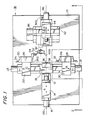
- FIG. 1 is a plan view of a headstock-reciprocating-type automatic lathe according to a first embodiment of this invention;
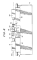
- FIG. 2 is a front elevational view, with a first cutter support block omitted, of the lathe of the first embodiment;
- FIG. 3 is a side elevational of the lathe of the first embodiment:
- FIG. 4 is a detail cross-sectional view of a second guide bush of the lathe of the first embodiment;
- FIGS. 5A through 5D show a cycle of progressive machining steps of the first embodiment;
- FIG. 6A shows a workpiece machined by a front machining according to the first embodiment;
- FIG. 6B shows a workpiece machined by first and second machinings according to the first embodiment;
- FIG. 7 is a plan view similar to FIG. 1, showing a second embodiment of this invention;
- FIG. 8 is a front elevational view, with parts broken away, of the lathe of the second embodiment;
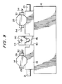
- FIG. 9 is a side elevational view of the lathe of the second embodiment;
- FIGS. 10A through 10D show a cycle of progressive machining steps of the second embodiment;
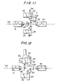
- FIG. 11 is a schematic plan view showing a third embodiment of this invention; and
- FIG. 12 is a view similar to FIG. 11, showing a fourth embodiment of this invention.
- The principles of this invention will be particularly useful when embodied in a headstock-reciprocating-type automatic lathe (hereinafter called "lathe") such as shown in FIGS. 1, 2 and 3.
- In the lathe, a
first headstock 14 is slidably movably carried on abase 12 fixed to abed 10. Thefirst headstock 14 is slidably movable on thebase 12 in a direction of an arrow A along afirst machining axis 100. - The movement of the
first headstock 14 is controlled by aservo motor 16 supported on thebase 12. Consequently, though there is no detailed illustration in the drawings, under the control of a computer according to a predetermined machining program, thefirst headstock 14 grips a blank material, e.g., an elongated or continuous-length cylindrical rod, then moves the blank material to a working point of a cutting tool (described below), and rotates the blank material for machining. Theheadstock 14 can be moved along thefirst machining axis 100 by theservo motor 16. - A
first tool post 20 and asecond tool post 22 are reciprocatingly slidably carried on a base 18 fixed to thebed 10. The first andsecond tool posts base 18 perpendicularly to thefirst machining axis 100 as indicated by arrows B, C, respectively. - The movements of the first and
second tool posts servo motors base 18. - A
first turret 24 and asecond turret 26 are rotatably supported on the first andsecond tool posts second turrets various cutting tools 32 and a second set ofvarious cutting tools 34 are detachably supported via a pair oftool holders - As the first and
second tool posts bed 18, thecutting tools axis 200. The working point of the workpiece is defined by the crossing point of the cuttingaxis 200 and the the workpiece. - It is a common knowledge that when locating the blank material in the working point, the overhang part of the blank material will be remarkably large in length if the blank material is supported at only one end by the
first headstock 14. To this end, the lathe is equipped with afirst guide bush 36 fixed to a firstguide bush holder 38 fixed to thebase 18. - The blank material is therefore intermediately guided near the working point by the
first guide bush 36 so that a desired precise machining can be performed by thecutting tools - According to this embodiment, for making a rear machining on the workpiece, a
slide base 42 is reciprocatingly slidably carried on a base 40 fixed to thebed 10. Theslide base 42 is reciprocatingly slidable in the direction of an arrow D along thefirst machining axis 100. - On this
slide base 42, asecond headstock 44 is carried so as to be reciprocatingly slidable in the direction of an arrow E perpendicular to thefirst machining axis 100. Consequently, thesecond head stock 44 is movable optionally either along thefirst machining axis 100 or in the direction perpendicular to thefirst machining axis 100. - A rear or second machining axis of the
second headstock 44 is designated by 300. Thesecond machining axis 300 is out of axial alignment with thefirst machining axis 100. Thesecond headstock 44 grips the other end of the workpiece on thefirst machining axis 100 and then slides in the direction of an arrow E to take a desired rear machining along thesecond machining axis 300. - A pair of
servo motors base 40 and theslide base 42 for moving thesecond headstock 44 in the optional direction of either the arrow D or the arrow E. - For a significant feature of this invention, the lathe is also equipped with a
second guide bush 50 for intermediately guiding the workpiece near the working point while the rear machining is being performed along thesecond machining axis 300 by thesecond headstock 44. In this embodiment, thesecond guide bush 50 is fixed to thebed 10 by a secondguide bush holder 52. - The
guide bush 50 is disposed in axial alignment with thesecond machining axis 300, and can intermediately guide the workpiece near a second working point as thesecond headstock 44 grips the workpiece and slides it along thesecond machining axis 300, as shown in phantom lines in FIG. 1. - The rear maching is performed by a
rear cutting tool 54 detachably held by thesecond turret 26; the crossing point of asecond cutting axis 400 and the workpiece defines the rear working point. - During this rear machining, if the
second headstock 44 supports the workpiece with a relatively large overhang thereof, e.g., if the extent of overhang is more than ten times the diameter of the gripped portion of the workpiece, it is possible to keep the workpiece in a proper posture against lateral pressure when the maching range is large, thus realizing a highly precise machining. - FIG. 4 shows a preferred example of the
second guide bush 50. In FIG. 4, thesecond guide bush 50 is firmly fastened to the secondguide bush holder 52 byscrews flange 50 of thesecond guide bush 50. - The
second guide bush 50 has a receivingtaper surface 50b on the workpiece side and can guide the workpiece exactly onto a guide surface 50C of thesecond guide bush 50. - FIGS. 5A through 5D show a cycle of progressive machining steps according to the first embodiment. FIG. 6A shows a workpiece machined by the front machining according to this embodiment, and FIG. 6B shows a workpiece machined by the front and rear machining.
- Specifically, in FIG. 5A, the front machining is performed as the
first headstock 14 grips the blank material M and moves the same along thefirst machining axis 100. Here the front machining is carried out by the cuttingtool 32 of thefirst turret 24. The thus machined workpiece is shown in FIG. 6A; substantially a half of the machining cycle is assigned to the front machining by the first headstock. - During this front machining, in the drawings, the
second headstock 44 stands by at a position remote from the working point along thefirst machining axis 100. Practically, however, thesecond headstock 44 is doing usually the rear maching during the front machining by thefirst headstock 14, as described below. - Upon completion of the front machining, as shown in FIG. 5B, the
first headstock 14 moves the blank material M and the workpiece W forwardly along thefirst machining axis 100 and, meanwhile, thesecond headstock 44 advances to receive the other end of the workpiece W. - In the illustrated embodiment, the workpiece W is severed from the blank material M at the final stage of the front machining, immediately before which the
second headstock 44 grips the other end of the workpiece W. Thus, the workpiece W on which the front machining has been completed and which is shown in FIG. 6A is assigned to thesecond headstock 44, whereupon the rear machining starts. - In FIG. 5C, a desired rear machining is performed by the
rear cutting tool 54 as thesecond headstock 44 slides the workpiece W onto thesecond maching axis 300, and then thesecond guide bush 50 intermediately guides the workpiece W. During this rear machining, the workpiece W projects or overhangs from thesecond headstock 44 to a relatively large extent. As is apparent from FIG. 5C, however, since the practical rear machining is carried out as the workpiece W is intermediately guided near the working point by thesecond guide bush 50, a highly precise machining can be achieved even when any large lateral pressure is exerted on the workpiece W. - Meanwhile, during this rear machining, the
first headstock 14 already grips the next blank material M to take the front machining. By thus performing the front and rear machinings concurrently, it is possible to shorten the entire machining cycle to a minimum. - In FIG. 5D, the workpiece W completed with the front and rear machinings is pulled out from the
second guide bush 50 by thesecond headstock 44 so that the workpiece may be discharged from the lathe. As a result, the workpiece W completed with the first and second machinings has been obtained as shown in FIG. 6B. The workpiece may be discharged by blowing air from the rear end of thesecond headstock 44, pushing out by a push rod via a cylinder unit or handling by a robot. - Also in FIG. 5D, during the discharging, the distance between the
second guide bush 50 and thesecond headstock 44 must be more than the length of the workpiece to take out the workpiece from thesecond headstock 44. - At that time, the
first headstock 14 has almost completed the front machining, and thesecond headstock 44 slides back to the position of FIG. 5A. The foregoing machining procedures are repeated. - As described above, according to this invention, since the second guide bush is used to support the other end of the workpiece so as to have an adequate overhang during the rear machining, the workpiece such as in the form of a cylindrical rod can be shaped not only at its end surface but also its side peripheral surface, thus expanding the range of the rear machining to a remarkable extent.
- Consequently, by performing the front and rear machinings concurrently, it is possible to shorten the entire machine cycle to a minimum.
- According to the first embodiment, since the second machining axis is located out of axial alignment with the first machining axis, the moving ranges of the cutting tools and other members can be set to adequate largeness. Therefore complex machinings of both the front and rear parts of the workpiece can be achieved.
- FIGS. 7, 8 and 9 show a modified lathe according to a second embodiment of this invention. Parts similar to those of the first embodiment are designated by like reference numerals; their detailed description is omitted here for clarity.
- For a significant feature of this second embodiment, the
second headstock 44 is slidable only along thefirst machining axis 100 and, unlike the first embodiment, is not slidable in a direction perpendicular to thefirst machining axis 100. - Likewise, the
second guide bush 50 is located in axial alignment with thefirst machining axis 100, and is supported by theguide bush holder 52 fixed to thebase 40. - The lathe of this second embodiment is simple in construction. Further, since the second headstock is from any lateral sliding movement, it is possible to shorten the machining cycle to such extent.
- To obtain adequate moving allowance for the individual cutting tools when performing the front and rear machinings concurrently, the
second headstock 44 moves along the first machining axis to an adequate extent, as indicated by the arrow D. - According to the second embodiment, in which the lathe has a common machining axis for the front and rear machinings, the workpiece can be supported at two points by the
first guide bush 36 and thesecond guide bush 50 during the front machining, if necessary. - FIGS. 10A through 10D show a cycle of progressive machining steps according to the second embodiment.
- FIG. 10A shows the front machining step by the
first headstock 14, during which thesecond headstock 44 is fully retracted to the right on thefirst machining axis 100. - FIG. 10B shows the step in which the workpiece W is severed off the blank material M. In this embodiment, the blank material M is advanced from the
first headstock 14 adequately, whereupon the workpiece W is cut off by the cuttingtool 54 as it is supported by thesecond guide bush 50. - With this two-point support system, an adequate ly large overhang of the workpiece can be obtained during the front machining. The rear machining and the front machining can be started directly from the position of FIG. 10B, thus shortening the machining cycle to a minimum.
- FIG. 10C shows the step in which the workpiece W severed off the blank material M is under the rear machining. At that time the blank material M is under the next front machining.
- FIG. 10D shows the step in which the workpiece W completed with the rear machining is being discharged as indicated by an arrow. The various members is returned from this position to the position of FIG. 10A ready for the next rear machining. The foregoing steps are repeated. Thus a shortened automatic machining cycle has been completed.
- FIG. 11 shows another modified lathe according to a third embodiment, in which the
second headstock 44 is movable only along thefirst machining axis 100, and thesecond guide bush 50 is slidable in a direction perpendicular to thefirst machining axis 100, as indicated by an arrow F. Thesecond guide bush 50 is retracted laterally from the first machining axis during the front machining, but can be located in alignment with thefirst machining axis 100 to perform a desired rear machining. Therefore, the lathe of this third embodiment is simple in construction. Further, easy and smooth movements of the cutting tools can be achieved within the machining range. - FIG. 12 shows still another modified lathe according to a fourth embodiment. Like the third embodiment, the
second headstock 44 is slidable only on thefirst machining axis 100, and thesecond guide bush 50 is slidable perpendicularly to thefirst machining axis 100. For a feature different from the third embodiment, thesecond guide bush 50 is substituted for the cutting tools carried by thesecond turret 26. Accordingly it is possible to achieve the function of this invention with simple construction. - In this illustrated embodiment, the front and rear machinings are carried out on the left and right ends, respectively, of the bed. Alternatively, the front and rear machinings may be performed on the first and second headstocks parallel to each other according to need. Using a known root, the workpiece completed with the front machining is gripped, whereupon the workpiece is reoriented and moved to the second headstock located adjacent to the first headstock so that the second machining can be performed by the second headstock.
- Alternatively, a plurality of second guide bushes different in diameter are arranged to meet with the shape of a workpiece. These second guide bushes may be optionally selectively used by a linear-drive index mechanism or a rotary index mechanism, or in combination thereof, which would cause an improved usefulness. Any combination of the foregoing changes and variations do not introduce new matter.
- To sum up the foregoing, according to this invention, since the second guide bush is added to intermediately guide the workpiece during the rear machining, it is possible to take an adequately large overhang of the workpiece during the rear machining. Consequently a variety of kinds of machinings can be possible. Further the entire machining cycle can be divided into front and rear machinings, thus shortening the machining cycle to a minimum.
- In machining a blank material on an automatic lathe of the type having first and second headstocks slidably carried along a bed, the first and second headstocks are slidable along their respective machining axes, and the first headstock grips the blank material to take a front machining, whereupon the semi-machined blank material, i.e., a workpiece is transferred to the second headstock to take a rear machining. The lathe also has first and second guide bushes for intermediately guiding the workpiece near the working point while the workpiece is gripped by the first and second headstocks. For machining a blank material in the form of a cylindrical rod continuously, the entire machining cycle can be divided into the front and rear machinings. Thus it is possible to shorten the machining cycle period.
Claims (6)
Applications Claiming Priority (2)
| Application Number | Priority Date | Filing Date | Title |
|---|---|---|---|
| JP63303301A JPH0716804B2 (en) | 1988-11-30 | 1988-11-30 | Spindle-sliding automatic lathe and machining method using the same |
| JP303301/88 | 1988-11-30 |
Publications (3)
| Publication Number | Publication Date |
|---|---|
| EP0371450A2 true EP0371450A2 (en) | 1990-06-06 |
| EP0371450A3 EP0371450A3 (en) | 1991-04-10 |
| EP0371450B1 EP0371450B1 (en) | 1995-04-12 |
Family
ID=17919311
Family Applications (1)
| Application Number | Title | Priority Date | Filing Date |
|---|---|---|---|
| EP89121917A Expired - Lifetime EP0371450B1 (en) | 1988-11-30 | 1989-11-28 | Headstock-reciprocating-type automatic lathe and machining method using the same |
Country Status (5)
| Country | Link |
|---|---|
| US (1) | US5152201A (en) |
| EP (1) | EP0371450B1 (en) |
| JP (1) | JPH0716804B2 (en) |
| KR (1) | KR940005906B1 (en) |
| DE (1) | DE68922189T2 (en) |
Cited By (12)
| Publication number | Priority date | Publication date | Assignee | Title |
|---|---|---|---|---|
| EP0476598A2 (en) * | 1990-09-21 | 1992-03-25 | Seiko Seiki Kabushiki Kaisha | NC Complex automatic lathe |
| US5207134A (en) * | 1991-01-21 | 1993-05-04 | Tsugami Corporation | Automatic precision lathe |
| US5239901A (en) * | 1992-09-11 | 1993-08-31 | Lin I Nan | CNC lathe |
| US5313694A (en) * | 1992-01-24 | 1994-05-24 | Takisawa Machine Tool Co., Ltd. | Machine tool for non-circular and other machining |
| EP0613745A1 (en) * | 1993-02-27 | 1994-09-07 | Star Micronics Co., Ltd. | Automatic lathe |
| US5421229A (en) * | 1993-04-29 | 1995-06-06 | Index-Werke Gmbh & Co. & Kg Hahn & Tessky | Automatic lathe |
| WO1997045221A1 (en) * | 1996-05-28 | 1997-12-04 | Traub Drehmaschinen Gmbh | Lathe, in particular a long-turning lathe, for working bar-shaped workpieces |
| EP1203634A1 (en) * | 2000-11-02 | 2002-05-08 | IEMCA Giuliani Macchine Italia S.p.A. | Transfer type machine tool |
| EP1340569A2 (en) * | 2002-02-28 | 2003-09-03 | IEMCA Giuliani Macchine Italia S.p.A. | A method and unit for machining parts in a transfer type machine tool |
| EP0888840B1 (en) * | 1997-06-12 | 2003-09-17 | Star Micronics Co., Ltd. | A cutting-off method of an automatic lathe and an automatic lathe |
| EP2548679A1 (en) * | 2010-03-18 | 2013-01-23 | Citizen Holdings Co., Ltd. | Machine tool |
| EP3241637A1 (en) * | 2016-05-03 | 2017-11-08 | Danobat, S. Coop. | Threading method and machine |
Families Citing this family (23)
| Publication number | Priority date | Publication date | Assignee | Title |
|---|---|---|---|---|
| DE9307155U1 (en) * | 1993-05-11 | 1993-08-19 | Traub Ag | Automatic lathe |
| US5676030A (en) * | 1995-08-14 | 1997-10-14 | Crudgington Machine Tools, Inc. | Multi-spindle CNC lathe |
| JPH09323201A (en) * | 1996-06-04 | 1997-12-16 | Dainichi Kinzoku Kogyo Kk | Turning method and lathe device to be used therefor |
| US5758554A (en) * | 1996-12-05 | 1998-06-02 | Miyano; Toshiharu Tom | Machine tool and method for machining a long-shafted workpiece |
| US6173630B1 (en) * | 1998-02-26 | 2001-01-16 | Hsuan Lung Wu | Working machine for machining a workpiece |
| US6446533B2 (en) * | 1999-08-20 | 2002-09-10 | Toshiharu Tom Miyano | Lathe assembly and method of using a lathe assembly |
| DE60037400T2 (en) * | 1999-10-28 | 2008-11-13 | Nakamura Tome Precision Industry Co. Ltd. | COMBINED TURNING MACHINE WITH NC CONTROL |
| US6675451B1 (en) * | 2000-05-10 | 2004-01-13 | Toshiharu Miyano | Machine tool and method of using the machine tool |
| US6807887B2 (en) * | 2000-06-08 | 2004-10-26 | Tri-Turn Technologies, Inc. | Multiple-spindle bar machine |
| US6637302B2 (en) * | 2001-03-22 | 2003-10-28 | Toshiharu Tom Miyano | Machining system and method of machining a workpiece using the machining system |
| JP4498631B2 (en) * | 2001-03-28 | 2010-07-07 | 株式会社ツガミ | Spindle movement type automatic lathe |
| JP2005111631A (en) * | 2003-10-09 | 2005-04-28 | Star Micronics Co Ltd | Nc automatic lathe |
| CN1886221B (en) * | 2003-12-26 | 2010-06-09 | 西铁城控股株式会社 | Automatic lathe |
| JP5139278B2 (en) * | 2006-05-30 | 2013-02-06 | 株式会社 ベアック | Drilling device |
| US7997173B2 (en) * | 2009-05-01 | 2011-08-16 | Teng Hung Wang | Adjustable tool supporting mechanism for machine tool |
| ATE516915T1 (en) | 2009-05-19 | 2011-08-15 | Teng-Hung Wang | ADJUSTABLE TOOL AUXILIARY MECHANISM FOR A MACHINE TOOL |
| US8387493B2 (en) * | 2010-10-18 | 2013-03-05 | Thomas P. Monroe | Modular lathe bed system |
| DE102011118747B4 (en) * | 2011-11-17 | 2015-07-02 | Emag Holding Gmbh | Method and machine tool for complete machining of wavy workpieces |
| KR102045424B1 (en) | 2012-11-12 | 2019-12-03 | 삼성디스플레이 주식회사 | X-ray generator, x-ray detector and method for taking x-ray images using the same |
| CN104014818B (en) * | 2014-03-18 | 2016-08-24 | 浙江华天机械有限公司 | The automatic turning device of a kind of bowl-type plug and automatic vehicle processing method |
| JP6259412B2 (en) | 2015-03-19 | 2018-01-10 | ファナック株式会社 | A numerical controller that performs reciprocating turning in a combined fixed cycle. |
| CN106862972A (en) * | 2017-03-28 | 2017-06-20 | 北京无线电测量研究所 | Turning machining device and its processing method after a kind of Ferrite Material die mould |
| KR102597690B1 (en) * | 2021-06-03 | 2023-11-02 | 주식회사바텍 | X-ray image apparatus |
Citations (7)
| Publication number | Priority date | Publication date | Assignee | Title |
|---|---|---|---|---|
| CH340111A (en) * | 1957-07-19 | 1959-07-31 | Caracteres Sa | Process for working parts which have to undergo several machining operations and machine for implementing this process |
| GB1141914A (en) * | 1966-08-12 | 1969-02-05 | Frank Sirola | Improvements in work support for receiving slender stock to be turned |
| EP0064766A2 (en) * | 1981-05-13 | 1982-11-17 | DSO "SAVODI sa METALOREJESCHTI MASCHINI" | Method and device for working pieces with rotational symmetry |
| FR2563454A1 (en) * | 1984-04-27 | 1985-10-31 | Myano Tekkosho Kk | MULTI-FUNCTION MACHINE-TOOL WITH TWO PINS |
| JPS62152603A (en) * | 1985-12-25 | 1987-07-07 | Tsugami Corp | Automatic lathe able to perform back machining |
| DE3609571A1 (en) * | 1986-03-21 | 1987-09-24 | Festo Kg | Apparatus for machining linearly extending, bar-shaped workpieces and methods of machining bar-shaped workpieces by means of the apparatus |
| DE3818667A1 (en) * | 1987-06-10 | 1988-12-29 | Volkswagen Ag | Lathe |
Family Cites Families (19)
| Publication number | Priority date | Publication date | Assignee | Title |
|---|---|---|---|---|
| GB1022625A (en) * | 1963-05-03 | 1966-03-16 | English Electric Co Ltd | Work rests in machine tools |
| FR1589103A (en) * | 1968-08-01 | 1970-03-23 | ||
| JPS5246389B2 (en) * | 1972-10-17 | 1977-11-24 | ||
| JPS5219388A (en) * | 1975-08-06 | 1977-02-14 | Star Seimitsu Kk | Automatic lathe |
| JPS5246389A (en) * | 1975-10-09 | 1977-04-13 | Meidensha Electric Mfg Co Ltd | Controller of ozonizer |
| JPS5322685A (en) * | 1976-08-13 | 1978-03-02 | Nomura Takayuki | Multiishaft automatic machine |
| JPS5933481B2 (en) * | 1979-05-22 | 1984-08-16 | 野村 孝之 | automatic lathing |
| JPS574441A (en) * | 1980-06-11 | 1982-01-11 | Maeden:Kk | Device for mounting loudspeaker on vehicle |
| CH636543A5 (en) * | 1980-07-16 | 1983-06-15 | Tarex Sa | MACHINE TOOL COMPRISING TWO OPPOSITE COAXIAL SPINDLES. |
| JPS6062401A (en) * | 1983-09-16 | 1985-04-10 | Citizen Watch Co Ltd | Back surface machining device of lathe |
| JPS60177801A (en) * | 1984-02-24 | 1985-09-11 | Hitachi Seiki Co Ltd | Turning machine tool |
| US4719676A (en) * | 1984-09-10 | 1988-01-19 | Wadell Equipment Company, Inc. | Flexible machining system |
| JPS6186102A (en) * | 1984-10-04 | 1986-05-01 | Citizen Watch Co Ltd | Automatic lathe |
| JPS62130102A (en) * | 1985-11-29 | 1987-06-12 | Citizen Watch Co Ltd | Numerically controlled automatic lathe |
| JPS63152603A (en) * | 1986-12-17 | 1988-06-25 | Showa Highpolymer Co Ltd | Photocurable resin composition |
| DE3812642A1 (en) * | 1987-04-17 | 1988-11-17 | Yamazaki Mazak Corp | Machine tool for complex machining and machining method for the use of the machine tool |
| JPS63300802A (en) * | 1987-05-29 | 1988-12-08 | Yamazaki Mazak Corp | Opposed-spindle lathe |
| EP0298672A3 (en) * | 1987-07-08 | 1989-12-06 | Wickman Bennett Machine Tool Company Limited | Multispindle lathe |
| JPS6421102A (en) * | 1987-07-15 | 1989-01-24 | De P Kensetsu Kogyo Kk | Method and device for bonding paving board |
-
1988
- 1988-11-30 JP JP63303301A patent/JPH0716804B2/en not_active Expired - Lifetime
-
1989
- 1989-11-28 DE DE68922189T patent/DE68922189T2/en not_active Expired - Fee Related
- 1989-11-28 EP EP89121917A patent/EP0371450B1/en not_active Expired - Lifetime
- 1989-11-30 KR KR1019890017788A patent/KR940005906B1/en not_active IP Right Cessation
-
1991
- 1991-06-27 US US07/725,391 patent/US5152201A/en not_active Expired - Fee Related
Patent Citations (7)
| Publication number | Priority date | Publication date | Assignee | Title |
|---|---|---|---|---|
| CH340111A (en) * | 1957-07-19 | 1959-07-31 | Caracteres Sa | Process for working parts which have to undergo several machining operations and machine for implementing this process |
| GB1141914A (en) * | 1966-08-12 | 1969-02-05 | Frank Sirola | Improvements in work support for receiving slender stock to be turned |
| EP0064766A2 (en) * | 1981-05-13 | 1982-11-17 | DSO "SAVODI sa METALOREJESCHTI MASCHINI" | Method and device for working pieces with rotational symmetry |
| FR2563454A1 (en) * | 1984-04-27 | 1985-10-31 | Myano Tekkosho Kk | MULTI-FUNCTION MACHINE-TOOL WITH TWO PINS |
| JPS62152603A (en) * | 1985-12-25 | 1987-07-07 | Tsugami Corp | Automatic lathe able to perform back machining |
| DE3609571A1 (en) * | 1986-03-21 | 1987-09-24 | Festo Kg | Apparatus for machining linearly extending, bar-shaped workpieces and methods of machining bar-shaped workpieces by means of the apparatus |
| DE3818667A1 (en) * | 1987-06-10 | 1988-12-29 | Volkswagen Ag | Lathe |
Cited By (17)
| Publication number | Priority date | Publication date | Assignee | Title |
|---|---|---|---|---|
| EP0476598A2 (en) * | 1990-09-21 | 1992-03-25 | Seiko Seiki Kabushiki Kaisha | NC Complex automatic lathe |
| EP0476598A3 (en) * | 1990-09-21 | 1992-08-05 | Seiko Seiki Kabushiki Kaisha | Nc complex automatic lathe |
| US5361472A (en) * | 1990-09-21 | 1994-11-08 | Seiko Seiki Kabushiki Kaisha | NC complex automatic lathe |
| US5207134A (en) * | 1991-01-21 | 1993-05-04 | Tsugami Corporation | Automatic precision lathe |
| US5313694A (en) * | 1992-01-24 | 1994-05-24 | Takisawa Machine Tool Co., Ltd. | Machine tool for non-circular and other machining |
| US5239901A (en) * | 1992-09-11 | 1993-08-31 | Lin I Nan | CNC lathe |
| EP0613745A1 (en) * | 1993-02-27 | 1994-09-07 | Star Micronics Co., Ltd. | Automatic lathe |
| US5421229A (en) * | 1993-04-29 | 1995-06-06 | Index-Werke Gmbh & Co. & Kg Hahn & Tessky | Automatic lathe |
| WO1997045221A1 (en) * | 1996-05-28 | 1997-12-04 | Traub Drehmaschinen Gmbh | Lathe, in particular a long-turning lathe, for working bar-shaped workpieces |
| EP0888840B1 (en) * | 1997-06-12 | 2003-09-17 | Star Micronics Co., Ltd. | A cutting-off method of an automatic lathe and an automatic lathe |
| EP1203634A1 (en) * | 2000-11-02 | 2002-05-08 | IEMCA Giuliani Macchine Italia S.p.A. | Transfer type machine tool |
| EP1340569A2 (en) * | 2002-02-28 | 2003-09-03 | IEMCA Giuliani Macchine Italia S.p.A. | A method and unit for machining parts in a transfer type machine tool |
| EP1340569A3 (en) * | 2002-02-28 | 2003-11-05 | IEMCA Giuliani Macchine Italia S.p.A. | A method and unit for machining parts in a transfer type machine tool |
| EP2548679A1 (en) * | 2010-03-18 | 2013-01-23 | Citizen Holdings Co., Ltd. | Machine tool |
| EP2548679A4 (en) * | 2010-03-18 | 2014-04-23 | Citizen Holdings Co Ltd | Machine tool |
| US8887601B2 (en) | 2010-03-18 | 2014-11-18 | Citizen Holdings Co., Ltd. | Machine tool |
| EP3241637A1 (en) * | 2016-05-03 | 2017-11-08 | Danobat, S. Coop. | Threading method and machine |
Also Published As
| Publication number | Publication date |
|---|---|
| US5152201A (en) | 1992-10-06 |
| DE68922189D1 (en) | 1995-05-18 |
| EP0371450A3 (en) | 1991-04-10 |
| JPH02152701A (en) | 1990-06-12 |
| KR940005906B1 (en) | 1994-06-24 |
| EP0371450B1 (en) | 1995-04-12 |
| DE68922189T2 (en) | 1995-09-28 |
| JPH0716804B2 (en) | 1995-03-01 |
| KR900007542A (en) | 1990-06-01 |
Similar Documents
| Publication | Publication Date | Title |
|---|---|---|
| EP0371450A2 (en) | Headstock-reciprocating-type automatic lathe and machining method using the same | |
| EP0827807B1 (en) | Long bar member machining apparatus and method | |
| JP5138258B2 (en) | Numerically controlled lathe provided with a guide bush and a method of machining a workpiece using the numerically controlled lathe | |
| US4831906A (en) | Numerical control machine | |
| JP2561577Y2 (en) | Opposing spindle lathe with tailstock holder | |
| JP2828232B2 (en) | Opposing spindle lathe | |
| JP3370760B2 (en) | Multi-axis automatic lathe | |
| JP4259653B2 (en) | Automatic lathe | |
| US6024001A (en) | Method of turning works and lathe for carrying out the method | |
| JPH0429482B2 (en) | ||
| GB2262061A (en) | Double spindle type lathe | |
| JP3439237B2 (en) | Lathe and lathe processing method | |
| EP0590753A1 (en) | Method and apparatus for machining workpieces | |
| JPH0542401A (en) | Nc machine tool | |
| JP2003245803A (en) | Processing method for slender work | |
| JP2001129701A (en) | Numerically controlled automatic lathe and method of machining workpiece by numerically controlled automatic lathe | |
| JP2003062701A (en) | Cnc lathe with counter spindle | |
| JPH08112701A (en) | Machining method executed on nc-lathe and nc-lathe capable of back up machining | |
| JP2656759B2 (en) | High precision nut manufacturing equipment | |
| JPH08118203A (en) | Control method of nc lathe and device thereof | |
| JP2002283103A (en) | Spindle moving type automatic lathe | |
| KR100227183B1 (en) | Multiple piston processing machine | |
| JPS6374502A (en) | Numerically controlled automatic lathe | |
| JPS63200915A (en) | Thread cutting method by numerically controlled lathe | |
| JP2002341914A (en) | Numerically controlled lathe having opposed comblike tool posts, method for machining work by the same and its program |
Legal Events
| Date | Code | Title | Description |
|---|---|---|---|
| PUAI | Public reference made under article 153(3) epc to a published international application that has entered the european phase |
Free format text: ORIGINAL CODE: 0009012 |
|
| AK | Designated contracting states |
Kind code of ref document: A2 Designated state(s): CH DE FR GB IT LI |
|
| PUAL | Search report despatched |
Free format text: ORIGINAL CODE: 0009013 |
|
| AK | Designated contracting states |
Kind code of ref document: A3 Designated state(s): CH DE FR GB IT LI |
|
| RHK1 | Main classification (correction) |
Ipc: B23Q 1/24 |
|
| 17P | Request for examination filed |
Effective date: 19910430 |
|
| 17Q | First examination report despatched |
Effective date: 19921105 |
|
| GRAA | (expected) grant |
Free format text: ORIGINAL CODE: 0009210 |
|
| AK | Designated contracting states |
Kind code of ref document: B1 Designated state(s): CH DE FR GB IT LI |
|
| REF | Corresponds to: |
Ref document number: 68922189 Country of ref document: DE Date of ref document: 19950518 |
|
| ITF | It: translation for a ep patent filed |
Owner name: SAIC BREVETTI S.R.L. |
|
| ET | Fr: translation filed | ||
| PG25 | Lapsed in a contracting state [announced via postgrant information from national office to epo] |
Ref country code: GB Effective date: 19951128 |
|
| PLBE | No opposition filed within time limit |
Free format text: ORIGINAL CODE: 0009261 |
|
| STAA | Information on the status of an ep patent application or granted ep patent |
Free format text: STATUS: NO OPPOSITION FILED WITHIN TIME LIMIT |
|
| 26N | No opposition filed | ||
| GBPC | Gb: european patent ceased through non-payment of renewal fee |
Effective date: 19951128 |
|
| PGFP | Annual fee paid to national office [announced via postgrant information from national office to epo] |
Ref country code: FR Payment date: 19991116 Year of fee payment: 11 |
|
| PGFP | Annual fee paid to national office [announced via postgrant information from national office to epo] |
Ref country code: CH Payment date: 19991119 Year of fee payment: 11 |
|
| PGFP | Annual fee paid to national office [announced via postgrant information from national office to epo] |
Ref country code: DE Payment date: 19991224 Year of fee payment: 11 |
|
| PG25 | Lapsed in a contracting state [announced via postgrant information from national office to epo] |
Ref country code: LI Free format text: LAPSE BECAUSE OF NON-PAYMENT OF DUE FEES Effective date: 20001130 Ref country code: CH Free format text: LAPSE BECAUSE OF NON-PAYMENT OF DUE FEES Effective date: 20001130 |
|
| REG | Reference to a national code |
Ref country code: CH Ref legal event code: PL |
|
| PG25 | Lapsed in a contracting state [announced via postgrant information from national office to epo] |
Ref country code: FR Free format text: LAPSE BECAUSE OF NON-PAYMENT OF DUE FEES Effective date: 20010731 |
|
| PG25 | Lapsed in a contracting state [announced via postgrant information from national office to epo] |
Ref country code: DE Free format text: LAPSE BECAUSE OF NON-PAYMENT OF DUE FEES Effective date: 20010801 |
|
| REG | Reference to a national code |
Ref country code: FR Ref legal event code: ST |
|
| PG25 | Lapsed in a contracting state [announced via postgrant information from national office to epo] |
Ref country code: IT Free format text: LAPSE BECAUSE OF NON-PAYMENT OF DUE FEES;WARNING: LAPSES OF ITALIAN PATENTS WITH EFFECTIVE DATE BEFORE 2007 MAY HAVE OCCURRED AT ANY TIME BEFORE 2007. THE CORRECT EFFECTIVE DATE MAY BE DIFFERENT FROM THE ONE RECORDED. Effective date: 20051128 |