EP0370851A1 - Fuel supply device for an internal combustion engine - Google Patents
Fuel supply device for an internal combustion engine Download PDFInfo
- Publication number
- EP0370851A1 EP0370851A1 EP89403021A EP89403021A EP0370851A1 EP 0370851 A1 EP0370851 A1 EP 0370851A1 EP 89403021 A EP89403021 A EP 89403021A EP 89403021 A EP89403021 A EP 89403021A EP 0370851 A1 EP0370851 A1 EP 0370851A1
- Authority
- EP
- European Patent Office
- Prior art keywords
- capacity
- movable wall
- pump
- engine
- volume
- Prior art date
- Legal status (The legal status is an assumption and is not a legal conclusion. Google has not performed a legal analysis and makes no representation as to the accuracy of the status listed.)
- Withdrawn
Links
Images
Classifications
-
- F—MECHANICAL ENGINEERING; LIGHTING; HEATING; WEAPONS; BLASTING
- F02—COMBUSTION ENGINES; HOT-GAS OR COMBUSTION-PRODUCT ENGINE PLANTS
- F02M—SUPPLYING COMBUSTION ENGINES IN GENERAL WITH COMBUSTIBLE MIXTURES OR CONSTITUENTS THEREOF
- F02M37/00—Apparatus or systems for feeding liquid fuel from storage containers to carburettors or fuel-injection apparatus; Arrangements for purifying liquid fuel specially adapted for, or arranged on, internal-combustion engines
- F02M37/20—Apparatus or systems for feeding liquid fuel from storage containers to carburettors or fuel-injection apparatus; Arrangements for purifying liquid fuel specially adapted for, or arranged on, internal-combustion engines characterised by means for preventing vapour lock
-
- F—MECHANICAL ENGINEERING; LIGHTING; HEATING; WEAPONS; BLASTING
- F02—COMBUSTION ENGINES; HOT-GAS OR COMBUSTION-PRODUCT ENGINE PLANTS
- F02M—SUPPLYING COMBUSTION ENGINES IN GENERAL WITH COMBUSTIBLE MIXTURES OR CONSTITUENTS THEREOF
- F02M5/00—Float-controlled apparatus for maintaining a constant fuel level
- F02M5/10—Float-controlled apparatus for maintaining a constant fuel level having means for preventing vapour lock, e.g. insulated float chambers or forced fuel circulation through float chamber with engine stopped
-
- Y—GENERAL TAGGING OF NEW TECHNOLOGICAL DEVELOPMENTS; GENERAL TAGGING OF CROSS-SECTIONAL TECHNOLOGIES SPANNING OVER SEVERAL SECTIONS OF THE IPC; TECHNICAL SUBJECTS COVERED BY FORMER USPC CROSS-REFERENCE ART COLLECTIONS [XRACs] AND DIGESTS
- Y10—TECHNICAL SUBJECTS COVERED BY FORMER USPC
- Y10S—TECHNICAL SUBJECTS COVERED BY FORMER USPC CROSS-REFERENCE ART COLLECTIONS [XRACs] AND DIGESTS
- Y10S261/00—Gas and liquid contact apparatus
- Y10S261/08—Carburetor primers
Definitions
- the present invention relates to fuel supply devices for an internal combustion engine, having a constant level tank supplied from a tank by a pump with mechanical drive by the engine.
- Mechanical drive pumps are generally attached directly to the motor housing to facilitate transmission of movement.
- the pump which is no longer cooled by the fuel passing through it when it is in operation, heats up. If the temperature under the hood is very high, the fuel contained in the pump vaporizes. If an attempt is made to restart the engine before cooling, the steam or air occupying the pump delays the fuel intake: this results in particular in a sudden running of the engine as soon as the tank at constant level s 'is emptied, not yet supplied by the pump.
- a supply device of the type has already been proposed in which a capacity is interposed between the tank and the pump and is separated from the tank by a non-return valve.
- the upper part of this capacity is connected to a source of pressurized air when the engine is started. The air drives the fuel contained in the capacity towards the pump.
- This solution requires introducing air into the capacity, which is not very favorable; it requires a source of pressurized air; it lacks progressiveness.
- the present invention aims to provide a supply device of the type defined above guaranteeing rapid priming of the pump when it contains gas or vapor as a result of heating.
- the capacity comprises a movable wall return means which tend to bring the movable wall into a position where the volume of the capacity is maximum and means for automatic displacement of the wall in the direction of the volume reduction in response to engine rotation.
- the displacement means are advantageously sensitive to the vacuum which appears in the intake duct of the engine as soon as it rotates, including under the action of the starter.
- These means can be constituted by a pneumatic capsule driving the movable wall.
- the latter may be a deformable membrane, subjected to the action of the return means which themselves will generally be constituted by a spring.
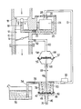
- the device shown by way of example in the figure uses displacement means sensitive to the vacuum created in the intake duct when the engine is rotated, which makes it possible to arrive at a simple, inexpensive and unlikely to fail.
- the supply device comprises a carburetor, the body 10 of which is pierced by an intake duct 12 which contains, arranged in this order from downstream to upstream, a throttling member 14 controlled by the driver, the outlet for a main fuel spouting system 16 and a starting flap (not shown).
- the outlet of the main spouting system is placed at the neck 18 of a venturi.
- the intake duct still open auxiliary circuits, not shown here because not concerned by the invention.
- the main spouting system 16 is fed by a constant level tank 20 via a main nozzle 22.
- the constant level tank shown is of the type having a float 24 provided with a needle 26 which closes an orifice intake 28 as soon as the fuel in the tank reaches a determined level.
- the intake port 28 is supplied by a mechanical pump 30 which draws the fuel from a tank 32 through a pipe 34 on which a non-return valve 36 is placed.
- Means for scanning the pump when the engine is started are interposed on line 34, between the non-return valve 36 and the pump 30. These means comprise a capacity 38 of variable volume.
- the capacity shown in the figure comprises a bottom formed by a movable wall 40, constituted by a deformable membrane 42 and cups 44 provided with a pusher 46.
- the periphery of the membrane 42 is pinched between a rigid wall of capacity 38 and a cover 48 which constitutes a stop.
- Return means constituted by a helical spring 50 placed in the capacity, exert on the movable wall 40 a force which tends to move it in a direction increasing the volume of the capacity 38.
- the displacement of the movable wall is limited by pressing a bulge of the pusher 46 against the cover 48.
- the capacity 38 is placed so as not to heat up as much as the pump 30, to avoid any percolation in this capacity; in particular, it will be removed from the engine.
- the motor means coupled to the movable wall 40 and making it possible to move it in a direction which reduces the volume of the capacity 38 when the motor is put in step include, in the case illustrated in the figure, a pneumatic capsule 52 subjected to the vacuum prevailing in the intake duct, downstream of the throttling member 14.
- the capsule 52 shown has a housing 54 trapping the periphery a membrane 56 and define with it a working chamber 58.
- the chamber 58 is connected to a point of the intake duct situated downstream of the main throttling member 14 by a channel 60 provided, in the mode of shown embodiment, of a throttle calibrator 62 whose role is to make the action of the capsule 52 more progressive. In some cases, this calibrator is unnecessary and can be omitted.
- the membrane 56 is coupled to the pusher 46 of the variable volume capacity by a rod 64: the rod has a terminal bend engaged in a transverse hole 70 of the pusher.
- Abutment means are generally provided to limit the movement of the membrane 56 under the action of the vacuum: in the case illustrated in the figure, they consist of a bulge 66 of the rod 64 and a flange 68 of the housing.
- the operation of the device is as follows.
- Chamber 38 has a maximum volume. It is filled with fuel from the tank 32 due to the suction by the pump 30 and then the last stroke of the movable wall when the engine has stopped.
- the vacuum which appears in the intake duct 12 is transmitted to the chamber 58.
- the pneumatic capsule 52 comes into action and pulls the rod 64, upwards in the figure.
- a fraction of the fuel contained in the capacity is returned to the pump 30 (the non-return valve 36 being closed). If the pump 30 has emptied of liquid fuel, due to its heating, the vapors contained in the pump 30 are discharged towards the carburetor, allowing a re-priming.
- the movable wall of the capacity 38 is maintained in a position where it gives the capacity the minimum volume fixed by the stop means 66, 68.
- the spring 50 brings the movable wall back to the stop position where it is shown in the figure and causes the suction of fuel through the valve 36.
Abstract
Description
La présente invention concerne les dispositifs d'alimentation en combustible pour moteur à combustion interne, ayant une cuve à niveau constant alimentée à partir d'un réservoir par une pompe à entraînement mécanique par le moteur.The present invention relates to fuel supply devices for an internal combustion engine, having a constant level tank supplied from a tank by a pump with mechanical drive by the engine.
Les pompes à entraînement mécanique sont en général fixées directement sur le carter du moteur pour faciliter la transmission de mouvement. Lorsque le moteur est arrêté alors qu'il est chaud, la pompe, qui n'est plus refroidie par le combustible qui la traverse lorsqu'elle est en fonctionnement, s'échauffe. Si la température sous capot est très élevée, le combustible contenu dans la pompe se vaporise. Si on tente de remettre le moteur en marche avant refroidissement, la vapeur ou l'air qui occupe la pompe retarde l'aspiration de combustible : cela se traduit notamment par un à-coup de fonctionnement du moteur dès que la cuve à niveau constant s'est vidée, n'étant pas encore alimentée par la pompe.Mechanical drive pumps are generally attached directly to the motor housing to facilitate transmission of movement. When the engine is stopped while it is hot, the pump, which is no longer cooled by the fuel passing through it when it is in operation, heats up. If the temperature under the hood is very high, the fuel contained in the pump vaporizes. If an attempt is made to restart the engine before cooling, the steam or air occupying the pump delays the fuel intake: this results in particular in a sudden running of the engine as soon as the tank at constant level s 'is emptied, not yet supplied by the pump.
On a déjà proposé un dispositif d'alimentation du type dans lequel une capacité est interposée entre le réservoir et la pompe et est séparée du réservoir par un clapet anti-retour. On relie la partie supérieure de cette capacité à une source d'air sous pression lors du démarrage du moteur. L'air chasse le combustible contenu dans la capacité vers la pompe.A supply device of the type has already been proposed in which a capacity is interposed between the tank and the pump and is separated from the tank by a non-return valve. The upper part of this capacity is connected to a source of pressurized air when the engine is started. The air drives the fuel contained in the capacity towards the pump.
Cette solution exige d'introduire de l'air dans la capacité, ce qui est peu favorable ; elle nécessite une source d'air sous pression ; elle manque de progressivité.This solution requires introducing air into the capacity, which is not very favorable; it requires a source of pressurized air; it lacks progressiveness.
La présente invention vise à fournir un dispositif d'alimentation du type ci-dessus défini garantissant un réamorçage rapide de la pompe lorsqu'elle contient du gaz ou de la vapeur par suite d'un échauffement.The present invention aims to provide a supply device of the type defined above guaranteeing rapid priming of the pump when it contains gas or vapor as a result of heating.
Dans ce but, la capacité comporte une paroi mobile des moyens de rappel qui tendent à amener la paroi mobile dans une position où le volume de la capacité est maximum et des moyens de déplacement automatique de la paroi dans le sens de la diminution de volume en réponse à la mise en rotation du moteur.For this purpose, the capacity comprises a movable wall return means which tend to bring the movable wall into a position where the volume of the capacity is maximum and means for automatic displacement of the wall in the direction of the volume reduction in response to engine rotation.
Les moyens de déplacement sont avantageusement sensibles à la dépression qui apparaît dans le conduit d'admission du moteur dès qu'il tourne, y compris sous l'action du démarreur. Ces moyens peuvent être constitués par une capsule pneumatique entraînant la paroi mobile. Cette dernière peut être une membrane déformable, soumise à l'action des moyens de rappel qui seront eux-mêmes en général constitués par un ressort.The displacement means are advantageously sensitive to the vacuum which appears in the intake duct of the engine as soon as it rotates, including under the action of the starter. These means can be constituted by a pneumatic capsule driving the movable wall. The latter may be a deformable membrane, subjected to the action of the return means which themselves will generally be constituted by a spring.
L'invention sera mieux comprise à la lecture de la description qui suit d'un mode particulier de réalisation, donné à titre d'exemple non limitatif. La description se réfère à la figure unique qui l'accompagne et montre schématiquement, en coupe suivant un plan vertical, les composants concernés par l'invention d'un dispositif d'alimentation.The invention will be better understood on reading the following description of a particular embodiment, given by way of non-limiting example. The description refers to the single figure which accompanies it and schematically shows, in section along a vertical plane, the components concerned by the invention of a supply device.
Le dispositif montré à titre d'exemple sur la figure utilise des moyens de déplacement sensibles à la dépression créée dans le conduit d'admission lors de la mise en rotation du moteur, ce qui permet d'arriver à une constitution simple, peu coûteuse et peu susceptible de panne.The device shown by way of example in the figure uses displacement means sensitive to the vacuum created in the intake duct when the engine is rotated, which makes it possible to arrive at a simple, inexpensive and unlikely to fail.
Le dispositif d'alimentation comporte un carburateur dont le corps 10 est percé d'un conduit d'admission 12 qui contient, disposé dans cet ordre d'aval en amont, un organe d'étranglement 14 commandé par le conducteur, le débouché d'un système de jaillissement principal de combustible 16 et un volet de départ (non représenté). Le débouché du système de jaillissement principal est placé au col 18 d'un venturi. Dans le conduit d'admission débouchent encore des circuits auxiliaires, non représentés ici car non concernés par l'invention.The supply device comprises a carburetor, the
Le système de jaillissement principal 16 est alimenté par une cuve à niveau constant 20 par l'intermédiaire d'un gicleur principal 22. La cuve à niveau constant représentée est du type ayant un flotteur 24 muni d'un pointeau 26 qui ferme un orifice d'admission 28 dès que le combustible dans la cuve atteint un niveau déterminé. L'orifice d'admission 28 est alimenté par une pompe mécanique 30 qui puise le combustible dans un réservoir 32 à travers une canalisation 34 sur laquelle est placé un clapet anti-retour 36.The
Des moyens permettant un balayage de la pompe lors du lancement du moteur sont interposés sur la conduite 34, entre le clapet anti-retour 36 et la pompe 30. Ces moyens comprennent une capacité 38 de volume variable. La capacité représentée sur la figure comporte un fond formé par une paroi mobile 40, constituée par une membrane déformable 42 et des coupelles 44 munie d'un poussoir 46. La périphérie de la membrane 42 est pincée entre une paroi rigide de la capacité 38 et un couvercle 48 qui constitue butée. Des moyens de rappel, constitués par un ressort en hélice 50 placé dans la capacité, exercent sur la paroi mobile 40 une force qui tend à la déplacer dans un sens augmentant le volume de la capacité 38. Le déplacement de la paroi mobile est limité par appui d'un renflement du poussoir 46 contre le couvercle 48.Means for scanning the pump when the engine is started are interposed on
La capacité 38 est placée de façon à ne pas s'échauffer autant que la pompe 30, pour éviter toute percolation dans cette capacité ; elle sera notamment écartée du moteur.The
Les moyens moteurs attelés à la paroi mobile 40 et permettant de la déplacer dans un sens qui réduit le volume de la capacité 38 lorsque le moteur est mis en marche comprennent, dans le cas illustré sur la figure, une capsule pneumatique 52 soumise à la dépression qui règne dans le conduit d'admission, en aval de l'organe d'étranglement 14. La capsule 52 représentée comporte un boîtier 54 emprisonnant la périphérie d'une membrane 56 et délimitent avec elle une chambre de travail 58. La chambre 58 est reliée à un point du conduit d'admission situé en aval de l'organe d'étranglement principal 14 par un canal 60 muni, dans le mode de réalisation représenté, d'un calibreur d'étranglement 62 dont le rôle est de rendre l'action de la capsule 52 plus progressive. Dans certains cas, ce calibreur est inutile et peut être omis.The motor means coupled to the
La membrane 56 est attelée au poussoir 46 de la capacité de volume variable par une tige 64 : la tige présente un coude terminal engagé dans un trou transversal 70 du poussoir. Des moyens de butée sont généralement prévus pour limiter le déplacement de la membrane 56 sous l'action de la dépression : dans le cas illustré sur la figure, ils sont constitués par un renflement 66 de la tige 64 et une collerette 68 du boîtier.The
Le fonctionnement du dispositif est le suivant.The operation of the device is as follows.
Lorsque le moteur est à l'arrêt, les éléments sont dans la position représentée sur la figure. La chambre 58 de la capsule pneumatique 52 est à la pression atmosphérique. La membrane 56 est équilibrée et la tige 64 n'exerce aucune force sur le poussoir 46 que le ressort 50 maintient en butée. La chambre 38 a un volume maximum. Elle est remplie de combustible provenant du réservoir 32 du fait de l'aspiration par la pompe 30 puis de la dernière course de la paroi mobile lorsque le moteur s'est arreté.When the engine is stopped, the elements are in the position shown in the figure. The
Lorsque le moteur est lancé, la dépression qui apparaît dans le conduit d'admission 12 est transmise à la chambre 58. La capsule pneumatique 52 entre en action et tire la tige 64, vers le haut sur la figure. Une fraction du combustible contenu dans la capacité est refoulée vers la pompe 30 (le clapet anti-retour 36 étant fermé). Si la pompe 30 s'est vidée de combustible liquide, du fait de son échauffement, les vapeurs contenues dans la pompe 30 sont refoulées vers le carburateur, permettant un réamorçage.When the engine is started, the vacuum which appears in the
Aussi longtemps que le moteur est en fonctionnement, la paroi mobile de la capacité 38 est maintenue dans une position où elle donne à la capacité le volume minimum fixé par les moyens de butée 66, 68.As long as the engine is in operation, the movable wall of the
Dès qu'on arrête le moteur, le ressort 50 ramène la paroi mobile dans la position de butée où elle est montrée sur la figure et provoque l'aspiration de combustible à travers le clapet 36.As soon as the engine is stopped, the
On voit qu'une diminution de volume de la capacité 38 intervient à chaque lancement du moteur, même si ce dernier est froid. Mais ce fonctionnement est sans inconvénient. Cependant des moyens peuvent être prévus pour permettre un retour au réservoir du combustible chassé par la capacité ou interdire le fonctionnement de la capsule pneumatique 52 en cas de lancement du moteur froid.It can be seen that a reduction in the volume of the
Claims (6)
Applications Claiming Priority (2)
| Application Number | Priority Date | Filing Date | Title |
|---|---|---|---|
| FR8814496 | 1988-11-07 | ||
| FR8814496A FR2638785B1 (en) | 1988-11-07 | 1988-11-07 | FUEL SUPPLY DEVICE FOR INTERNAL COMBUSTION ENGINE |
Publications (1)
| Publication Number | Publication Date |
|---|---|
| EP0370851A1 true EP0370851A1 (en) | 1990-05-30 |
Family
ID=9371626
Family Applications (1)
| Application Number | Title | Priority Date | Filing Date |
|---|---|---|---|
| EP89403021A Withdrawn EP0370851A1 (en) | 1988-11-07 | 1989-11-02 | Fuel supply device for an internal combustion engine |
Country Status (4)
| Country | Link |
|---|---|
| US (1) | US5063891A (en) |
| EP (1) | EP0370851A1 (en) |
| BR (1) | BR8905883A (en) |
| FR (1) | FR2638785B1 (en) |
Families Citing this family (5)
| Publication number | Priority date | Publication date | Assignee | Title |
|---|---|---|---|---|
| US5526795A (en) * | 1994-03-10 | 1996-06-18 | Ford Motor Company | High pressure pumpless fuel system |
| EP0786591A3 (en) * | 1996-01-29 | 1997-08-13 | WCI OUTDOOR PRODUCTS, Inc. | Fast start fuel system for an internal combustion engine |
| DE29812679U1 (en) * | 1998-07-16 | 1998-10-01 | Stihl Maschf Andreas | Pressure compensation system for a fuel tank of an internal combustion engine, in particular for hand-held, portable tools |
| US6874482B2 (en) * | 2003-05-06 | 2005-04-05 | Wacker Corporation | Diaphragm carburetor with air purge system |
| US7267326B2 (en) * | 2005-05-05 | 2007-09-11 | Tecumseh Products Company | Automatic priming system |
Citations (2)
| Publication number | Priority date | Publication date | Assignee | Title |
|---|---|---|---|---|
| US4129106A (en) * | 1971-06-14 | 1978-12-12 | Sellman Donald L | Vapor lock and fuel vaporization controls |
| FR2564903A1 (en) * | 1984-05-25 | 1985-11-29 | Noisier Guy | Internal combustion engine feed device with constant level vessel |
Family Cites Families (6)
| Publication number | Priority date | Publication date | Assignee | Title |
|---|---|---|---|---|
| JPS5037806B1 (en) * | 1971-03-10 | 1975-12-05 | ||
| JPS58192963A (en) * | 1982-05-01 | 1983-11-10 | Sanshin Ind Co Ltd | Controlling device for fuel of internal-combustion engine |
| JPS6183474A (en) * | 1984-09-29 | 1986-04-28 | Teikei Kikaki Kk | Starting device of diaphragm type carburetor |
| US4735751A (en) * | 1986-05-27 | 1988-04-05 | Tecumseh Products Company | Primer system and method for priming an internal combustion engine |
| US4684484A (en) * | 1986-05-27 | 1987-08-04 | Tecumseh Products Company | Primer system and method for priming an internal combustion engine |
| US4814114A (en) * | 1988-07-21 | 1989-03-21 | Walbro Corporation | Diaphragm-controlled carburetor with manual fuel enrichment |
-
1988
- 1988-11-07 FR FR8814496A patent/FR2638785B1/en not_active Expired - Fee Related
-
1989
- 1989-10-23 US US07/425,336 patent/US5063891A/en not_active Expired - Fee Related
- 1989-11-02 EP EP89403021A patent/EP0370851A1/en not_active Withdrawn
- 1989-11-06 BR BR898905883A patent/BR8905883A/en unknown
Patent Citations (2)
| Publication number | Priority date | Publication date | Assignee | Title |
|---|---|---|---|---|
| US4129106A (en) * | 1971-06-14 | 1978-12-12 | Sellman Donald L | Vapor lock and fuel vaporization controls |
| FR2564903A1 (en) * | 1984-05-25 | 1985-11-29 | Noisier Guy | Internal combustion engine feed device with constant level vessel |
Non-Patent Citations (1)
| Title |
|---|
| PATENT ABSTRACTS OF JAPAN, vol. 10, no. 257 (M-513)[2313], 3 septembre 1986, page 81 M 513; & JP-A-61 83 474 (TEIKEI KIKAKI K.K.) 28-04-1986 * |
Also Published As
| Publication number | Publication date |
|---|---|
| US5063891A (en) | 1991-11-12 |
| FR2638785A1 (en) | 1990-05-11 |
| FR2638785B1 (en) | 1991-01-25 |
| BR8905883A (en) | 1990-06-12 |
Similar Documents
| Publication | Publication Date | Title |
|---|---|---|
| BE1008861A5 (en) | Engine fuel system for internal. | |
| FR2698915A1 (en) | Vapor recovery assembly for fuel system. | |
| BE897463A (en) | FUEL SUPPLY SYSTEM FOR AN INTERNAL COMBUSTION ENGINE | |
| FR2616895A1 (en) | SUCTION BATTERY EQUIPPED WITH A SLIDE VALVE, DESIGNED TO REMOVE A-CUPS FROM SUCTION BY REFRIGERANT LIQUID | |
| EP0370851A1 (en) | Fuel supply device for an internal combustion engine | |
| EP0786045B1 (en) | Two-stroke engine comprising an enhanced injection device and associated injection method | |
| EP2890612B1 (en) | Drainage method and purge collector of a carburation system of a helicopter | |
| FR2490733A2 (en) | Heated fuel feed for diesel engine - has thermostatic flow valve incorporated in filter to save space | |
| FR2463271A1 (en) | FUEL INJECTION PUMP FOR INTERNAL COMBUSTION ENGINES | |
| FR2633013A1 (en) | FUEL PUMP | |
| FR2693767A1 (en) | Fuel injection device for a two-stroke engine. | |
| FR2472668A1 (en) | FUEL ENRICHMENT DEVICE FOR GAS FUEL MIXERS | |
| EP0374038B1 (en) | Cooling device for an internal-combustion engine | |
| FR2517746A1 (en) | RECOVERY PUMP DEVICE FOR CARBURETOR | |
| FR2681102A1 (en) | FUEL INJECTION PUMP FOR A TWO-STROKE ENGINE. | |
| FR2937685A1 (en) | METHOD AND APPARATUS FOR GAS BLEEDING OF A FUEL DOSER AND FUEL LEVEL RETENTION | |
| FR2485095A1 (en) | IMPROVEMENTS ON RECOVERY PUMP CARBURETORS | |
| FR2481371A1 (en) | HOT RESET VALVE FOR MEMBRANE CARBURETOR | |
| FR2686946A1 (en) | CARBURETOR FOR A THERMAL ENGINE. | |
| FR2640694A1 (en) | Evaporator/pressure-reducing device | |
| BE1004144A5 (en) | System fuel. | |
| FR2564903A1 (en) | Internal combustion engine feed device with constant level vessel | |
| CH219476A (en) | Device for injecting fuel into the supply line of an internal combustion engine. | |
| FR2523651A1 (en) | Accelerator pump for carburettor - has connection to float bowl via duct controlled by valve actuated by choke | |
| FR3106386A1 (en) | Mechanical valve for an aqueous solution injection system on board a vehicle |
Legal Events
| Date | Code | Title | Description |
|---|---|---|---|
| PUAI | Public reference made under article 153(3) epc to a published international application that has entered the european phase |
Free format text: ORIGINAL CODE: 0009012 |
|
| AK | Designated contracting states |
Kind code of ref document: A1 Designated state(s): DE ES GB IT |
|
| 17P | Request for examination filed |
Effective date: 19901107 |
|
| 17Q | First examination report despatched |
Effective date: 19910416 |
|
| STAA | Information on the status of an ep patent application or granted ep patent |
Free format text: STATUS: THE APPLICATION IS DEEMED TO BE WITHDRAWN |
|
| 18D | Application deemed to be withdrawn |
Effective date: 19930427 |