EP0370685A2 - Cable adjuster - Google Patents
Cable adjuster Download PDFInfo
- Publication number
- EP0370685A2 EP0370685A2 EP89311816A EP89311816A EP0370685A2 EP 0370685 A2 EP0370685 A2 EP 0370685A2 EP 89311816 A EP89311816 A EP 89311816A EP 89311816 A EP89311816 A EP 89311816A EP 0370685 A2 EP0370685 A2 EP 0370685A2
- Authority
- EP
- European Patent Office
- Prior art keywords
- tube
- prongs
- housing
- release member
- adjuster
- Prior art date
- Legal status (The legal status is an assumption and is not a legal conclusion. Google has not performed a legal analysis and makes no representation as to the accuracy of the status listed.)
- Granted
Links
Images
Classifications
-
- F—MECHANICAL ENGINEERING; LIGHTING; HEATING; WEAPONS; BLASTING
- F16—ENGINEERING ELEMENTS AND UNITS; GENERAL MEASURES FOR PRODUCING AND MAINTAINING EFFECTIVE FUNCTIONING OF MACHINES OR INSTALLATIONS; THERMAL INSULATION IN GENERAL
- F16C—SHAFTS; FLEXIBLE SHAFTS; ELEMENTS OR CRANKSHAFT MECHANISMS; ROTARY BODIES OTHER THAN GEARING ELEMENTS; BEARINGS
- F16C1/00—Flexible shafts; Mechanical means for transmitting movement in a flexible sheathing
- F16C1/10—Means for transmitting linear movement in a flexible sheathing, e.g. "Bowden-mechanisms"
-
- F—MECHANICAL ENGINEERING; LIGHTING; HEATING; WEAPONS; BLASTING
- F16—ENGINEERING ELEMENTS AND UNITS; GENERAL MEASURES FOR PRODUCING AND MAINTAINING EFFECTIVE FUNCTIONING OF MACHINES OR INSTALLATIONS; THERMAL INSULATION IN GENERAL
- F16C—SHAFTS; FLEXIBLE SHAFTS; ELEMENTS OR CRANKSHAFT MECHANISMS; ROTARY BODIES OTHER THAN GEARING ELEMENTS; BEARINGS
- F16C1/00—Flexible shafts; Mechanical means for transmitting movement in a flexible sheathing
- F16C1/26—Construction of guiding-sheathings or guiding-tubes
- F16C1/262—End fittings; Attachment thereof to the sheathing or tube
-
- F—MECHANICAL ENGINEERING; LIGHTING; HEATING; WEAPONS; BLASTING
- F16—ENGINEERING ELEMENTS AND UNITS; GENERAL MEASURES FOR PRODUCING AND MAINTAINING EFFECTIVE FUNCTIONING OF MACHINES OR INSTALLATIONS; THERMAL INSULATION IN GENERAL
- F16C—SHAFTS; FLEXIBLE SHAFTS; ELEMENTS OR CRANKSHAFT MECHANISMS; ROTARY BODIES OTHER THAN GEARING ELEMENTS; BEARINGS
- F16C1/00—Flexible shafts; Mechanical means for transmitting movement in a flexible sheathing
- F16C1/10—Means for transmitting linear movement in a flexible sheathing, e.g. "Bowden-mechanisms"
- F16C1/22—Adjusting; Compensating length
- F16C1/226—Adjusting; Compensating length by adjusting the effective length of the sheathing
Definitions
- a Bowden cable consists of an inner part, herein called a wire, and a surrounding tubular outer part, herein called a sleeve.
- Such cables are used for example for vehicle clutch operation and in those situations the sleeve is held stationery and the wire moves axially along the sleeve.
- the wire is connected between the clutch operating member e.g. pedal at one end and some part of the clutch mechanism at the other end.
- the clutch operating member e.g. pedal at one end and some part of the clutch mechanism at the other end.
- the clutch operating member e.g. pedal at one end and some part of the clutch mechanism at the other end.
- Another prior art method is to locate one sleeve end in a screw adjuster, usually a male screwthreaded tube forming a continuation of the sleeve and engaged in a female threaded lug so as to form an end stop for the cable.
- a locknut fixes the position. Adjustment can be difficult if the end stop is inaccessible.
- One object of the invention is to provide improvements. Another object is to provide automatic adjustment.
- a Bowden cable adjuster comprises a tube for receiving an end of the sleeve of said cable and forming a continuation of said sleeve, a housing supporting said tube, and means permitting adjustment of the position of said tube relative to said housing, characterised in that said means permitting adjustment comprise a starlock washer supported on said housing and having prongs frictionally engaged with said tube, said prongs being inclined to the plane of the said washer so as to allow unidirectional movement only of said tube.
- an automatic adjuster for a Bowden cable comprises a tube for receiving one end of the sleeve of the cable and for an extension thereof through which the wire of the cable extends, a release member surrounding said tube and having one end within said tube for effecting adjustment, and the opposite end of said member located outside the tube being arranged to be contacted by a cable operating member, a housing receiving and guiding the said release member for sliding movement therein, a starlock washer supported by the housing, having prongs radially inwardly directed and inclined to an acute angle with respect to the axis of the release member, said prongs engaging the said tube, said release member one end abutting said prongs, and spring means urging the starlock washer into the housing and urging the said tube away from the said opposite end of the said release member so as to draw the said tube through the starlock washer when the prongs are displaced by the release member which in turn is displaced by contact with the cable operating member.
- the adjuster shown comprises a housing generally indicated by the reference numeral 10 which comprises a cup 12 and a tube 14 extending concentrically of the cup and from the base thereof.
- This housing 10 is to be located and possibly fixed in relation to a vehicle bulkhead shown in dash lines at 16. Any required spacer 18 and washers 20 may be provided between the cup and the bulkhead in order to give a desired axial location according to circumstances.
- the adjuster further comprises a locking tube generally indicated by the reference numeral 24 and which comprises a smaller diameter tubular portion 26 and a larger diameter tubular portion 28.
- the portion 28 is dimensioned internally to receive one end of the sleeve of the Bowden cable therein, so that the sleeve extends away generally as indicated in the chain dot line at 30.
- the wire of the cable extends throughout the adjuster and is connected for example by a fixed nipple to the clutch pedal mechanism in the vicinity of the reference 32 at the left hand side of the adjuster as illustrated.
- the adjuster further comprises a release member 34 which is tubular, is a free sliding fit in the tube 14, and receives the smaller diameter portion 26 of the locking tube in its bore, also as a free sliding fit therein.
- a spring abutment 36 is a shallow cup located on the locking tube and seating against a shoulder formed adjacent the junction of the two different diameter portions.
- a starlock washer 40 is located in the cup 12 and this washer has a generally domed or conical shape with a series of prongs projecting radially inwardly and with the tips of those prongs engaged with the locking sleeve. Hence the prongs are inclined to the plane containing the outer periphery of the washer.
- the release member 34 has one end abutting the starlock washer adjacent the free ends of those prongs.
- a pair of helical compression springs is employed, namely an outer spring 42 which extends between the spring abutment cup 36 at one end and the outer periphery of the starlock washer at the other end, and this spring 42 serves to retain the starlock washer in the housing.
- a loose abutment washer 44 is located on the locking sleeve and has a frusto conical face of wider angle than the cone of the starlock washer adjacent the starlock washer and its opposite face forms a cup to receive and locate one end of the inner spring 46. The opposite end of that spring also seats on the spring abutment cup 36.
- the washer 44 abuts the ends of the prongs adjacent to the locking sleeve so that those prongs are in effect trapped between the washer and the release member at their tips.
- a spacer washer such as 50 may be located on the wire and between the nipple on the wire and the release member, or the part 50 may be considered to be the actual clutch actuating part itself, fixed to the wire e.g. by a nipple 32.
- the parts When installed, the parts are adjusted so that with the clutch engaged the nipple (or clutch actuating member) in the position 32 contacts the spacer 50 which contacts the end of the release sleeve.
- the clutch When the clutch is operated, that is disengaged, the wire moves in the direction of the arrow A applying a compressive load to the Bowden sleeve 30. Any tendency for the locking tube 26 to slide in the release member 34 is resisted by the starlock washer and the tips of the prongs which frictionally engage the part 26.
- the adjuster of the present invention provides automatic self-adjustment of the Bowden cable.
- the wear rate is expected to be low and each adjustment may be over a relatively small distance.
Landscapes
- Engineering & Computer Science (AREA)
- General Engineering & Computer Science (AREA)
- Health & Medical Sciences (AREA)
- Oral & Maxillofacial Surgery (AREA)
- Mechanical Engineering (AREA)
- Insulated Conductors (AREA)
- Flexible Shafts (AREA)
- Control Of Motors That Do Not Use Commutators (AREA)
- Manufacturing Of Electric Cables (AREA)
- Mechanical Operated Clutches (AREA)
- Glass Compositions (AREA)
- Laying Of Electric Cables Or Lines Outside (AREA)
Abstract
Description
- This invention relates to adjusters for Bowden cables. A Bowden cable consists of an inner part, herein called a wire, and a surrounding tubular outer part, herein called a sleeve. Such cables are used for example for vehicle clutch operation and in those situations the sleeve is held stationery and the wire moves axially along the sleeve. The wire is connected between the clutch operating member e.g. pedal at one end and some part of the clutch mechanism at the other end. As the clutch wears, extra movement is needed. Sometimes the actual travel required for clutch operation may remain constant but the location of the wire ends becomes progressively further away from the position occupied before any wear had occurred. In either situation adjustment may be made so as to keep the operating member in the same position, by varying the relative length of the wire and sleeve or displacing one end of the sleeve to a new adjusted position.
- In the prior art, one method of adjustment has been provided by a nipple fixed to the wire by a screw, allowing release, re-positioning of the nipple and retightening of the screw. This has the disadvantage that in order to clamp sufficiently tight it is necessary for the screw to bite into the wire which may be difficult or may damage the wire. Correct screw pressure is extremely critical.
- Another prior art method is to locate one sleeve end in a screw adjuster, usually a male screwthreaded tube forming a continuation of the sleeve and engaged in a female threaded lug so as to form an end stop for the cable. A locknut fixes the position. Adjustment can be difficult if the end stop is inaccessible.
- Other arrangements have provided the equivalent of a screwthread on a formation of the sleeve itself, in attempts to provide the same effect but at reduced cost.
- One object of the invention is to provide improvements. Another object is to provide automatic adjustment.
- According to the invention a Bowden cable adjuster comprises a tube for receiving an end of the sleeve of said cable and forming a continuation of said sleeve, a housing supporting said tube, and means permitting adjustment of the position of said tube relative to said housing, characterised in that said means permitting adjustment comprise a starlock washer supported on said housing and having prongs frictionally engaged with said tube, said prongs being inclined to the plane of the said washer so as to allow unidirectional movement only of said tube.
- Also according to the invention, an automatic adjuster for a Bowden cable comprises a tube for receiving one end of the sleeve of the cable and for an extension thereof through which the wire of the cable extends, a release member surrounding said tube and having one end within said tube for effecting adjustment, and the opposite end of said member located outside the tube being arranged to be contacted by a cable operating member, a housing receiving and guiding the said release member for sliding movement therein, a starlock washer supported by the housing, having prongs radially inwardly directed and inclined to an acute angle with respect to the axis of the release member, said prongs engaging the said tube, said release member one end abutting said prongs, and spring means urging the starlock washer into the housing and urging the said tube away from the said opposite end of the said release member so as to draw the said tube through the starlock washer when the prongs are displaced by the release member which in turn is displaced by contact with the cable operating member.
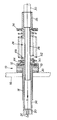
- One embodiment of the invention is now more particularly described with reference to the accompanying drawing wherein the sole Figure is a sectional elevation of an adjuster mechanism for a Bowden cable.
- Referring to the drawing, the part shown is intended for use as an automatic clutch adjuster for a motor vehicle. The adjuster shown comprises a housing generally indicated by the
reference numeral 10 which comprises acup 12 and atube 14 extending concentrically of the cup and from the base thereof. Thishousing 10 is to be located and possibly fixed in relation to a vehicle bulkhead shown in dash lines at 16. Any required spacer 18 andwashers 20 may be provided between the cup and the bulkhead in order to give a desired axial location according to circumstances. - The adjuster further comprises a locking tube generally indicated by the
reference numeral 24 and which comprises a smaller diametertubular portion 26 and a larger diametertubular portion 28. Theportion 28 is dimensioned internally to receive one end of the sleeve of the Bowden cable therein, so that the sleeve extends away generally as indicated in the chain dot line at 30. The wire of the cable extends throughout the adjuster and is connected for example by a fixed nipple to the clutch pedal mechanism in the vicinity of thereference 32 at the left hand side of the adjuster as illustrated. - The adjuster further comprises a
release member 34 which is tubular, is a free sliding fit in thetube 14, and receives thesmaller diameter portion 26 of the locking tube in its bore, also as a free sliding fit therein. - A
spring abutment 36 is a shallow cup located on the locking tube and seating against a shoulder formed adjacent the junction of the two different diameter portions. - A
starlock washer 40 is located in thecup 12 and this washer has a generally domed or conical shape with a series of prongs projecting radially inwardly and with the tips of those prongs engaged with the locking sleeve. Hence the prongs are inclined to the plane containing the outer periphery of the washer. Therelease member 34 has one end abutting the starlock washer adjacent the free ends of those prongs. - A pair of helical compression springs is employed, namely an
outer spring 42 which extends between thespring abutment cup 36 at one end and the outer periphery of the starlock washer at the other end, and thisspring 42 serves to retain the starlock washer in the housing. - A
loose abutment washer 44 is located on the locking sleeve and has a frusto conical face of wider angle than the cone of the starlock washer adjacent the starlock washer and its opposite face forms a cup to receive and locate one end of theinner spring 46. The opposite end of that spring also seats on thespring abutment cup 36. Thewasher 44 abuts the ends of the prongs adjacent to the locking sleeve so that those prongs are in effect trapped between the washer and the release member at their tips. - A spacer washer such as 50 may be located on the wire and between the nipple on the wire and the release member, or the
part 50 may be considered to be the actual clutch actuating part itself, fixed to the wire e.g. by anipple 32. - When installed, the parts are adjusted so that with the clutch engaged the nipple (or clutch actuating member) in the
position 32 contacts thespacer 50 which contacts the end of the release sleeve. When the clutch is operated, that is disengaged, the wire moves in the direction of the arrow A applying a compressive load to the Bowdensleeve 30. Any tendency for thelocking tube 26 to slide in therelease member 34 is resisted by the starlock washer and the tips of the prongs which frictionally engage thepart 26. - During wear on the clutch the clutch end of the wire, i.e. the opposite end of the wire to the
point 32 moves progressively away from the adjuster, so that increasing pressure is applied on theadjuster sleeve 34 until the right hand end of the same (in the drawing) displaces the prongs to ease their frictional engagement to enable thesprings point 32 away from the adjuster again so as to reduce the load applied to the starlock washer allowing the prongs to grip and lock the adjuster in the new position. The inclination of the prongs makes the possible movement of the locking tube unidirectional. - Hence the adjuster of the present invention provides automatic self-adjustment of the Bowden cable. In ordinary use of a clutch the wear rate is expected to be low and each adjustment may be over a relatively small distance.
Claims (6)
Priority Applications (1)
| Application Number | Priority Date | Filing Date | Title |
|---|---|---|---|
| AT89311816T ATE104026T1 (en) | 1988-11-23 | 1989-11-15 | CABLE ADJUSTMENT DEVICE. |
Applications Claiming Priority (2)
| Application Number | Priority Date | Filing Date | Title |
|---|---|---|---|
| GB8827383 | 1988-11-23 | ||
| GB888827383A GB8827383D0 (en) | 1988-11-23 | 1988-11-23 | Cable adjuster |
Publications (3)
| Publication Number | Publication Date |
|---|---|
| EP0370685A2 true EP0370685A2 (en) | 1990-05-30 |
| EP0370685A3 EP0370685A3 (en) | 1990-10-17 |
| EP0370685B1 EP0370685B1 (en) | 1994-04-06 |
Family
ID=10647341
Family Applications (1)
| Application Number | Title | Priority Date | Filing Date |
|---|---|---|---|
| EP89311816A Expired - Lifetime EP0370685B1 (en) | 1988-11-23 | 1989-11-15 | Cable adjuster |
Country Status (9)
| Country | Link |
|---|---|
| EP (1) | EP0370685B1 (en) |
| JP (1) | JPH02217605A (en) |
| KR (1) | KR900008187A (en) |
| AT (1) | ATE104026T1 (en) |
| DE (1) | DE68914407T2 (en) |
| DK (1) | DK583489A (en) |
| ES (1) | ES2055101T3 (en) |
| GB (2) | GB8827383D0 (en) |
| PT (1) | PT92394B (en) |
Cited By (6)
| Publication number | Priority date | Publication date | Assignee | Title |
|---|---|---|---|---|
| WO1994018462A1 (en) * | 1993-02-09 | 1994-08-18 | Simplistik Design (Uk) Limited | Self-adjusting cable assembly |
| FR2708059A1 (en) * | 1993-07-22 | 1995-01-27 | Blg Systemes | Automatic adjustment device for a control cable |
| EP0743463A2 (en) * | 1995-04-28 | 1996-11-20 | Bowden Controls Limited | Bi-directional locking device for use in an adjustable cable or rod control system |
| WO1998025786A1 (en) * | 1996-12-09 | 1998-06-18 | Magna Interior Systems Inc. | Method of installing a bowden wire assembly and the resulting installation |
| ES2188394A1 (en) * | 2001-09-17 | 2003-06-16 | Castellon Melchor Daumal | Control cable with self-adjusting tension. |
| DE102005021669A1 (en) * | 2005-05-06 | 2006-11-16 | Huf Hülsbeck & Fürst Gmbh & Co. Kg | Method for tolerance correction in door lock system especially in automobiles has one end of a Bowden cable outer on a sprung ratchet mount for axial adjustment |
Families Citing this family (3)
| Publication number | Priority date | Publication date | Assignee | Title |
|---|---|---|---|---|
| GB2260588A (en) * | 1991-10-09 | 1993-04-21 | Rover Group | A clutch cable adjuster |
| GB2275316A (en) * | 1993-02-19 | 1994-08-24 | Ford Motor Co | Adjustable cable installation in a motor vehicle |
| CN105626731B (en) * | 2014-10-31 | 2018-07-27 | 北京宇航系统工程研究所 | A kind of cut spring suitable for small-sized installation space |
Citations (4)
| Publication number | Priority date | Publication date | Assignee | Title |
|---|---|---|---|---|
| DE2101209A1 (en) * | 1971-01-12 | 1972-07-20 | Siemens Ag | Device for automatically maintaining a defined air gap in an electromagnetic clutch or brake |
| US4378713A (en) * | 1980-06-10 | 1983-04-05 | Acco Industries Inc. | Self-adjusting cable control device |
| FR2553479A1 (en) * | 1983-10-14 | 1985-04-19 | Dba | Cable control unit with adjustment element |
| FR2595841A1 (en) * | 1986-01-22 | 1987-09-18 | Bendix France | Mechanical control device with cable having automatic adjustment |
-
1988
- 1988-11-23 GB GB888827383A patent/GB8827383D0/en active Pending
-
1989
- 1989-11-15 DE DE68914407T patent/DE68914407T2/en not_active Expired - Fee Related
- 1989-11-15 ES ES89311816T patent/ES2055101T3/en not_active Expired - Lifetime
- 1989-11-15 EP EP89311816A patent/EP0370685B1/en not_active Expired - Lifetime
- 1989-11-15 AT AT89311816T patent/ATE104026T1/en not_active IP Right Cessation
- 1989-11-20 GB GB8926187A patent/GB2225403B/en not_active Expired - Fee Related
- 1989-11-21 DK DK583489A patent/DK583489A/en not_active Application Discontinuation
- 1989-11-22 JP JP1304510A patent/JPH02217605A/en active Pending
- 1989-11-23 PT PT92394A patent/PT92394B/en not_active IP Right Cessation
- 1989-11-23 KR KR1019890017226A patent/KR900008187A/en not_active Application Discontinuation
Patent Citations (4)
| Publication number | Priority date | Publication date | Assignee | Title |
|---|---|---|---|---|
| DE2101209A1 (en) * | 1971-01-12 | 1972-07-20 | Siemens Ag | Device for automatically maintaining a defined air gap in an electromagnetic clutch or brake |
| US4378713A (en) * | 1980-06-10 | 1983-04-05 | Acco Industries Inc. | Self-adjusting cable control device |
| FR2553479A1 (en) * | 1983-10-14 | 1985-04-19 | Dba | Cable control unit with adjustment element |
| FR2595841A1 (en) * | 1986-01-22 | 1987-09-18 | Bendix France | Mechanical control device with cable having automatic adjustment |
Cited By (7)
| Publication number | Priority date | Publication date | Assignee | Title |
|---|---|---|---|---|
| WO1994018462A1 (en) * | 1993-02-09 | 1994-08-18 | Simplistik Design (Uk) Limited | Self-adjusting cable assembly |
| FR2708059A1 (en) * | 1993-07-22 | 1995-01-27 | Blg Systemes | Automatic adjustment device for a control cable |
| EP0743463A2 (en) * | 1995-04-28 | 1996-11-20 | Bowden Controls Limited | Bi-directional locking device for use in an adjustable cable or rod control system |
| EP0743463B1 (en) * | 1995-04-28 | 1999-11-24 | Adwest Bowden Tsk Limited | Bi-directional locking device for use in an adjustable cable or rod control system |
| WO1998025786A1 (en) * | 1996-12-09 | 1998-06-18 | Magna Interior Systems Inc. | Method of installing a bowden wire assembly and the resulting installation |
| ES2188394A1 (en) * | 2001-09-17 | 2003-06-16 | Castellon Melchor Daumal | Control cable with self-adjusting tension. |
| DE102005021669A1 (en) * | 2005-05-06 | 2006-11-16 | Huf Hülsbeck & Fürst Gmbh & Co. Kg | Method for tolerance correction in door lock system especially in automobiles has one end of a Bowden cable outer on a sprung ratchet mount for axial adjustment |
Also Published As
| Publication number | Publication date |
|---|---|
| ES2055101T3 (en) | 1994-08-16 |
| DE68914407T2 (en) | 1994-07-21 |
| GB2225403A (en) | 1990-05-30 |
| KR900008187A (en) | 1990-06-02 |
| ATE104026T1 (en) | 1994-04-15 |
| PT92394A (en) | 1990-05-31 |
| DK583489A (en) | 1990-05-24 |
| PT92394B (en) | 1995-09-12 |
| GB8827383D0 (en) | 1988-12-29 |
| GB2225403B (en) | 1992-08-12 |
| GB8926187D0 (en) | 1990-01-10 |
| EP0370685B1 (en) | 1994-04-06 |
| JPH02217605A (en) | 1990-08-30 |
| DK583489D0 (en) | 1989-11-21 |
| EP0370685A3 (en) | 1990-10-17 |
| DE68914407D1 (en) | 1994-05-11 |
Similar Documents
| Publication | Publication Date | Title |
|---|---|---|
| US5138897A (en) | Cable adjuster | |
| EP0286269A1 (en) | Control cable assembly | |
| US4598809A (en) | Cable-and-sleeve connector | |
| US4658668A (en) | Transmission kickdown cable adjuster | |
| EP0312382B1 (en) | Control cable adjuster device | |
| EP0048620A1 (en) | Cable-and-sleeve connector | |
| US4799400A (en) | Self-adjusting cable control device | |
| EP0936703A2 (en) | Contact device | |
| EP0120616B1 (en) | Improvements in or relating to cable-and-sleeve connectors | |
| EP0167612B1 (en) | Clutch control mechanism with auto-adjuster | |
| EP0370685A2 (en) | Cable adjuster | |
| US4955252A (en) | Cable-and-sleeve connections | |
| US20030024082A1 (en) | Spring clip | |
| EP0118520B1 (en) | Self-adjusting clutch mechanism | |
| US7530288B2 (en) | Automatic adjust assembly with release lock | |
| US4580665A (en) | Quick connect brake coupling | |
| GB2176861A (en) | Device for automatically regulating tension applied to inner wire of control cable for slack adjustment | |
| EP0234864B1 (en) | Control cable adjuster device | |
| US4549709A (en) | Device for attaching to a wall the end of a sheath in which a control cable is slidably received | |
| GB2260588A (en) | A clutch cable adjuster | |
| US4424890A (en) | Manual clutch wear adjuster | |
| GB2157789A (en) | Self-adjusting clutch control mechanism | |
| US5489011A (en) | Vehicle clutch cable self-adjusting mechanism | |
| EP0267685A2 (en) | Control cable adjuster device | |
| GB2174168A (en) | Self-adjusting clutch control cable |
Legal Events
| Date | Code | Title | Description |
|---|---|---|---|
| PUAI | Public reference made under article 153(3) epc to a published international application that has entered the european phase |
Free format text: ORIGINAL CODE: 0009012 |
|
| AK | Designated contracting states |
Kind code of ref document: A2 Designated state(s): AT BE CH DE ES FR GB GR IT LI LU NL SE |
|
| PUAL | Search report despatched |
Free format text: ORIGINAL CODE: 0009013 |
|
| AK | Designated contracting states |
Kind code of ref document: A3 Designated state(s): AT BE CH DE ES FR GB GR IT LI LU NL SE |
|
| 17P | Request for examination filed |
Effective date: 19901227 |
|
| 17Q | First examination report despatched |
Effective date: 19911028 |
|
| GRAA | (expected) grant |
Free format text: ORIGINAL CODE: 0009210 |
|
| AK | Designated contracting states |
Kind code of ref document: B1 Designated state(s): AT BE CH DE ES FR GB GR IT LI LU NL SE |
|
| PG25 | Lapsed in a contracting state [announced via postgrant information from national office to epo] |
Ref country code: SE Free format text: THE PATENT HAS BEEN ANNULLED BY A DECISION OF A NATIONAL AUTHORITY Effective date: 19940406 Ref country code: LI Effective date: 19940406 Ref country code: GR Free format text: LAPSE BECAUSE OF FAILURE TO SUBMIT A TRANSLATION OF THE DESCRIPTION OR TO PAY THE FEE WITHIN THE PRESCRIBED TIME-LIMIT Effective date: 19940406 Ref country code: CH Effective date: 19940406 Ref country code: BE Effective date: 19940406 Ref country code: AT Effective date: 19940406 |
|
| REF | Corresponds to: |
Ref document number: 104026 Country of ref document: AT Date of ref document: 19940415 Kind code of ref document: T |
|
| REF | Corresponds to: |
Ref document number: 68914407 Country of ref document: DE Date of ref document: 19940511 |
|
| ITF | It: translation for a ep patent filed |
Owner name: ING. A. GIAMBROCONO & C. S.R.L. |
|
| REG | Reference to a national code |
Ref country code: CH Ref legal event code: PL |
|
| REG | Reference to a national code |
Ref country code: ES Ref legal event code: FG2A Ref document number: 2055101 Country of ref document: ES Kind code of ref document: T3 |
|
| ET | Fr: translation filed | ||
| RAP2 | Party data changed (patent owner data changed or rights of a patent transferred) |
Owner name: QUINTON HAZELL PLC |
|
| NLT2 | Nl: modifications (of names), taken from the european patent patent bulletin |
Owner name: QUINTON HAZELL PLC TE NUNEATON, GROOT-BRITTANNIE. |
|
| PG25 | Lapsed in a contracting state [announced via postgrant information from national office to epo] |
Ref country code: GB Effective date: 19941115 |
|
| PG25 | Lapsed in a contracting state [announced via postgrant information from national office to epo] |
Ref country code: ES Free format text: LAPSE BECAUSE OF NON-PAYMENT OF DUE FEES Effective date: 19941116 |
|
| PG25 | Lapsed in a contracting state [announced via postgrant information from national office to epo] |
Ref country code: LU Free format text: LAPSE BECAUSE OF NON-PAYMENT OF DUE FEES Effective date: 19941130 |
|
| REG | Reference to a national code |
Ref country code: GB Ref legal event code: 732E |
|
| PLBE | No opposition filed within time limit |
Free format text: ORIGINAL CODE: 0009261 |
|
| STAA | Information on the status of an ep patent application or granted ep patent |
Free format text: STATUS: NO OPPOSITION FILED WITHIN TIME LIMIT |
|
| 26N | No opposition filed | ||
| PG25 | Lapsed in a contracting state [announced via postgrant information from national office to epo] |
Ref country code: NL Effective date: 19950601 |
|
| GBPC | Gb: european patent ceased through non-payment of renewal fee |
Effective date: 19941115 |
|
| NLV4 | Nl: lapsed or anulled due to non-payment of the annual fee | ||
| PG25 | Lapsed in a contracting state [announced via postgrant information from national office to epo] |
Ref country code: FR Effective date: 19950731 |
|
| PG25 | Lapsed in a contracting state [announced via postgrant information from national office to epo] |
Ref country code: DE Effective date: 19950801 |
|
| REG | Reference to a national code |
Ref country code: FR Ref legal event code: ST |
|
| REG | Reference to a national code |
Ref country code: ES Ref legal event code: FD2A Effective date: 19951214 |
|
| PG25 | Lapsed in a contracting state [announced via postgrant information from national office to epo] |
Ref country code: IT Free format text: LAPSE BECAUSE OF NON-PAYMENT OF DUE FEES Effective date: 20051115 |