EP0369739A1 - Contact - Google Patents
Contact Download PDFInfo
- Publication number
- EP0369739A1 EP0369739A1 EP89311770A EP89311770A EP0369739A1 EP 0369739 A1 EP0369739 A1 EP 0369739A1 EP 89311770 A EP89311770 A EP 89311770A EP 89311770 A EP89311770 A EP 89311770A EP 0369739 A1 EP0369739 A1 EP 0369739A1
- Authority
- EP
- European Patent Office
- Prior art keywords
- leg members
- contact
- socket
- contacts
- bridge portion
- Prior art date
- Legal status (The legal status is an assumption and is not a legal conclusion. Google has not performed a legal analysis and makes no representation as to the accuracy of the status listed.)
- Withdrawn
Links
Images

Classifications
-
- H—ELECTRICITY
- H01—ELECTRIC ELEMENTS
- H01R—ELECTRICALLY-CONDUCTIVE CONNECTIONS; STRUCTURAL ASSOCIATIONS OF A PLURALITY OF MUTUALLY-INSULATED ELECTRICAL CONNECTING ELEMENTS; COUPLING DEVICES; CURRENT COLLECTORS
- H01R13/00—Details of coupling devices of the kinds covered by groups H01R12/70 or H01R24/00 - H01R33/00
- H01R13/02—Contact members
- H01R13/10—Sockets for co-operation with pins or blades
- H01R13/11—Resilient sockets
- H01R13/115—U-shaped sockets having inwardly bent legs, e.g. spade type
-
- H—ELECTRICITY
- H01—ELECTRIC ELEMENTS
- H01R—ELECTRICALLY-CONDUCTIVE CONNECTIONS; STRUCTURAL ASSOCIATIONS OF A PLURALITY OF MUTUALLY-INSULATED ELECTRICAL CONNECTING ELEMENTS; COUPLING DEVICES; CURRENT COLLECTORS
- H01R4/00—Electrically-conductive connections between two or more conductive members in direct contact, i.e. touching one another; Means for effecting or maintaining such contact; Electrically-conductive connections having two or more spaced connecting locations for conductors and using contact members penetrating insulation
- H01R4/24—Connections using contact members penetrating or cutting insulation or cable strands
- H01R4/2416—Connections using contact members penetrating or cutting insulation or cable strands the contact members having insulation-cutting edges, e.g. of tuning fork type
- H01R4/242—Connections using contact members penetrating or cutting insulation or cable strands the contact members having insulation-cutting edges, e.g. of tuning fork type the contact members being plates having a single slot
Definitions
- pin spacing is close, a typical example being 2.54mm where pin size is 0.635mm. It has been a problem to produce socket contacts by stamping and forming from sheet material using simple tooling of a size capable of accepting a square pin of a size such as 0.635mm square formed at a pitch of 2.54mm. The problem exists for other sizes and pitches.
- the terminal portion may be an insulating displacement contact portion.
- the invention further provides a stamped sheet of conductive material suitable for forming a series of contacts for use in a female connector, which stamped sheet provides an elongate attachment portion and a multiplicity of planar contact portions arranged side by side and attached to said attachment portion, each contact portion having a bridge portion, a pair of leg members extending from the bridge portion and being formable into a contact according to the invention, spacing of the contact portions corresponding to the pitch of pins of a male connector assembly with which the female connector is to mate, in use.
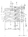
- FIG. 1 illustrates a series of contacts 10 stamped from conducting sheet material 11.
- Each contact 10 has an insulation displacement portion 12 although it will be appreciated that other types of terminal portion could be used.
- Each contact 10 has a pair of leg members 13, 14 connected by a bridge portion 15.
- FIG. 2 illustrates clearly how small the bridge portion becomes when in U-shape and the leg members are formed at this stage with respective outwardly cranked portions 16, 17 and inwardly cranked portions 18, 19 in the leg members 13, 14.
- the leg members are formed with further outwardly cranked portions 20, 21 respectively at their free ends to allow ease of acceptance of a pin in use.
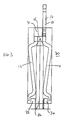
- Figure 3 shows a contact 10 in position within a female connector block 30.
- the block 30 has a passageway 31 therethrough, from one end of which emerges the terminal portion 12 and through the other end of which passes a pin 32.
- the small dimension of the bridge portion 15 advantageously allows the passageway 31 to be of small dimension at that end thereof.
- Ribs 33 and 34 extend into the passageway to lie inside free ends of the legs 13 and 14 to act as stops to prevent the leg members 13 and 14 approaching each other too closely at the reduced spacing region and thus causing difficulty of entry of the pin 32.
- Forming contacts in this shape allows spacing of the contacts in the stamped sheet to be much closer than has hitherto been possible and enables socket contacts to be able to accept a standard pin size and yet still be stamped at 2.54mm pitch, yet requiring no complex metal forming to produce a workable configuration.
- the fact that a simple operation is involved in formation of the leg shapes means that gold coating of selected parts can be carried out before formation while the contacts are all still held together. Since the socket pitch is the same as the pin pitch, each row of sockets can be inserted in a single operation rather than a double operation which has hitherto been necessary where sockets have been formed at double pin pitch.
Abstract
A socket contact (10) is capable of being stamped from sheet material and subsequently formed. The contact has a socket portion for accepting a pin and a terminal portion (12). The socket portion has a pair of mutually facing leg members (13,14) and a bridge portion (15) joining the leg members (13,14). The bridge portion (15) is substantially U-shaped with spacing of the leg members (13,14) where they extend from the bridge portion (15) being less than the size of the pin to be accepted. The leg members (13,14) are cranked to provide a maximum spacing between the leg members (13,14) towards the ends thereof joined by the bridge portion (15) and a reduced spacing between the leg members (13,14) in the region of their free ends to provide resiliently biased contact with a pin, in use.
Description
- The invention relates to contacts, and more particularly to contacts for use in multi contact socket assemblies for mating with multi pin male connector elements.
- In multi pin contacts, pin spacing is close, a typical example being 2.54mm where pin size is 0.635mm. It has been a problem to produce socket contacts by stamping and forming from sheet material using simple tooling of a size capable of accepting a square pin of a size such as 0.635mm square formed at a pitch of 2.54mm. The problem exists for other sizes and pitches.
- Elaborate proposals have been made, or simple proposals for a U-shaped socket having parallel spaced contact arms have meant that, in order to provide adequate socket size for pin acceptance, the pitch of socket formation is greater than the pin pitch, so that sockets have to be stamped at double pin pitch, resulting in a double insertion step of socket rows into a connector body to achieve sockets at the desired pitch.
- According to the invention there is provided a socket contact capable of being stamped from sheet material and subsequently formed, which contact comprises a socket portion for accepting a pin, in use, and a terminal portion for connection to a conductor or the like, the socket portion comprising a pair of mutually facing leg members between which a pin is engageable, in use, and a bridge portion joining the leg members remote from their free ends, the bridge portion being substantially U-shaped with spacing of the leg members where they extend from the bridge portion being less than the size of the pin to be accepted by the socket, the leg members having a cranked profile to provide a maximum spacing between the leg members towards the ends thereof joined by the bridge portion and a reduced spacing between the leg members in the region of their free ends to provide resiliently biased contact with a pin, in use.
- The free ends of the leg members may open away from one another to ease entry of a pin, in use.
- The leg members may be gold coated in the region of reduced spacing.
- The terminal portion may be an insulating displacement contact portion.
- The invention further provides a stamped sheet of conductive material suitable for forming a series of contacts for use in a female connector, which stamped sheet provides an elongate attachment portion and a multiplicity of planar contact portions arranged side by side and attached to said attachment portion, each contact portion having a bridge portion, a pair of leg members extending from the bridge portion and being formable into a contact according to the invention, spacing of the contact portions corresponding to the pitch of pins of a male connector assembly with which the female connector is to mate, in use.
- The invention further provides a series of contacts according to the invention stamped from sheet material and connected together by material of said sheet prior to insertion into a female connector block, spacing of the contacts corresponding to the pitch of pins of a male connector assembly with which the female connector is to mate, in use.
- The invention further provides a method of making socket contacts according to the invention ready for insertion into a female connector block at a pitch corresponding to the pitch of pins in a corresponding male connector assembly, which method comprises stamping planar contact portions from flat sheet material such that the contact portions are connected together by material of said sheet, each contact portion having a bridge portion and a pair of leg members extending from the bridge portion, forming the contacts by bending the bridge portion of each contact portion to form a U-shape, and cranking the leg members to provide said maximum and reduced leg member spacings.
- The method may include a step of gold coating the leg members in the reduced spacing region after stamping but prior to forming the final shape.
- The invention further provides a method of making and inserting contacts according to the invention into a female connector block comprising the method of making contacts according to the invention and a further step of inserting formed contacts into the female connector block at the pitch of pins with which the sockets are to mate, in use.
- The insertion step preferably includes a step of inserting the contacts connected together by material of the sheet, and removing the connecting sheet material after insertion.
- By way of example, one embodiment of a socket contact according to the invention and a method of manufacturing the contact will now be described with reference to the accompanying drawings, in which:-
- Figure 1 is a plan view of a series of socket contacts stamped from sheet material but not formed into final contact shape;
- Figure 2 is a perspective view of a complete socket contact according to the invention; and
- Figure 3 is a side view of the socket contact of Figure 2 located in material of a female connector block and engaged by a pin of a male connector.
- Figure 1 illustrates a series of
contacts 10 stamped from conducting sheet material 11. Eachcontact 10 has aninsulation displacement portion 12 although it will be appreciated that other types of terminal portion could be used. Eachcontact 10 has a pair ofleg members bridge portion 15. - The length of the
bridge portion 15 is such that if theleg members bridge portion 15 bent into a U-shape, the spacing of theleg members contacts 10 are stamped corresponds, however, to the pitch commonly used in connectors, namely 2.54mm, this being achieved by the shortness of thebridge portion 15 in thecontacts 10. - Subsequent to stamping, the bridge portion and leg members are formed to provide the final contact shape shown in Figure 2. Figure 2 illustrates clearly how small the bridge portion becomes when in U-shape and the leg members are formed at this stage with respective outwardly cranked
portions 16, 17 and inwardly crankedportions leg members bridge portion 15 and a reduced spacing in a region towards the free ends of theleg members - The leg members are formed with further outwardly cranked
portions - Prior to formation of the shape shown in Figure 2, the regions of the
leg members - Figure 3 shows a
contact 10 in position within a female connector block 30. The block 30 has apassageway 31 therethrough, from one end of which emerges theterminal portion 12 and through the other end of which passes apin 32. The small dimension of thebridge portion 15 advantageously allows thepassageway 31 to be of small dimension at that end thereof. -
Ribs legs leg members pin 32. - Figure 3 illustrates clearly how the
pin 32 is substantially larger than the U-shapebridge portion 15 and how the cranking of theleg members pin 32 between the leg members in the region of their free ends. - Forming contacts in this shape allows spacing of the contacts in the stamped sheet to be much closer than has hitherto been possible and enables socket contacts to be able to accept a standard pin size and yet still be stamped at 2.54mm pitch, yet requiring no complex metal forming to produce a workable configuration. The fact that a simple operation is involved in formation of the leg shapes means that gold coating of selected parts can be carried out before formation while the contacts are all still held together. Since the socket pitch is the same as the pin pitch, each row of sockets can be inserted in a single operation rather than a double operation which has hitherto been necessary where sockets have been formed at double pin pitch.
- It will be appreciated that the foregoing description is by way of example only and that modifications and alterations may be made within the scope of the invention.
Claims (10)
1. A socket contact capable of being stamped from sheet material and subsequently formed, which contact comprises a socket portion for accepting a pin, in use, and a terminal portion for connection to a conductor or the like, the socket portion comprising a pair of mutually facing leg members between which a pin is engageable, in use, and a bridge portion joining the leg members remote from their free ends, the bridge portion being substantially U-shaped with spacing of the leg members where they extend from the bridge portion being less than the size of the pin to be accepted by the socket, the leg members having a cranked profile to provide a maximum spacing between the leg members towards the ends thereof joined by the bridge portion and a reduced spacing between the leg members in the region of their free ends to provide resiliently biased contact with a pin, in use.
2. A socket contact as claimed in Claim 1 wherein the free ends of the leg members open away from one another to ease entry of a pin, in use.
3. A socket contact as claimed in Claim 1 or Claim 2 wherein the leg members are gold coated in the region of reduced spacing.
4. A socket contact as claimed in any one of Claims 1 to 3 wherein the terminal portion is an insulating displacement contact portion.
5. A stamped sheet of conductive material suitable for forming a series of contacts for use in a female connector, which stamped sheet provides an elongate attachment portion and a multiplicity of planar contact portions arranged side by side and attached to said attachment portion, each contact portion having a bridge portion, a pair of leg members extending from the bridge portion and being formable into a contact as claimed in any one of Claims 1 to 4, spacing of the contact portions corresponding to the pitch of pins of a male connector assembly with which the female connector is to mate, in use.
6. A series of contacts as claimed in any one of Claims 1 to 4 stamped from sheet material and connected together by material of said sheet prior to insertion into a female connector block, spacing of the contacts corresponding to the pitch of pins of a male connector assembly with which the female connector is to mate, in use.
7. A method of making socket contacts as claimed in any one of Claims 1 to 4 or 6 ready for insertion into a female connector block at a pitch corresponding to the pitch of pins in a corresponding male connector assembly, which method comprises stamping planar contact portions from flat sheet material, such that the contact portions are connected together by material of said sheet, each contact portion having a bridge portion and a pair of leg members extending from the bridge portion, forming the contacts by bending the bridge portion of each contact to form a U-shape, and cranking the leg members to provide said maximum and reduced leg spacings.
8. A method as claimed in Claim 7 comprising a step of gold coating the leg members in the reduced spacing region after stamping but prior to forming the final shape.
9. A method of making and inserting socket contacts as claimed in any one of Claims 1 to 4 into a female connector block comprising the method as claimed in Claim 7 or Claim 8 and a further step of inserting formed contacts into the female connector block at the pitch of pins with which the sockets are to mate, in use.
10. A method as claimed in Claim 9 wherein the insertion step includes a step of inserting the contacts connected together by material of the sheet, and removing the connecting sheet material after insertion.
Applications Claiming Priority (2)
| Application Number | Priority Date | Filing Date | Title |
|---|---|---|---|
| GB888826969A GB8826969D0 (en) | 1988-11-18 | 1988-11-18 | Improvements in contacts |
| GB8826969 | 1988-11-18 |
Publications (1)
| Publication Number | Publication Date |
|---|---|
| EP0369739A1 true EP0369739A1 (en) | 1990-05-23 |
Family
ID=10647062
Family Applications (1)
| Application Number | Title | Priority Date | Filing Date |
|---|---|---|---|
| EP89311770A Withdrawn EP0369739A1 (en) | 1988-11-18 | 1989-11-14 | Contact |
Country Status (4)
| Country | Link |
|---|---|
| EP (1) | EP0369739A1 (en) |
| JP (1) | JPH02244571A (en) |
| AU (1) | AU4469089A (en) |
| GB (1) | GB8826969D0 (en) |
Cited By (1)
| Publication number | Priority date | Publication date | Assignee | Title |
|---|---|---|---|---|
| DE19905717A1 (en) * | 1999-02-11 | 2000-08-17 | Delphi Tech Inc | Fastener |
Families Citing this family (1)
| Publication number | Priority date | Publication date | Assignee | Title |
|---|---|---|---|---|
| JPH0754730B2 (en) * | 1991-05-24 | 1995-06-07 | 鴻海精密工業股▲分▼有限公司 | Connector socket contact and manufacturing method thereof |
Citations (2)
| Publication number | Priority date | Publication date | Assignee | Title |
|---|---|---|---|---|
| FR2270694A1 (en) * | 1974-05-09 | 1975-12-05 | Bunker Ramo | |
| DE3441134A1 (en) * | 1984-11-10 | 1986-05-15 | Cannon Electric Gmbh | Test plug having socket contacts, and a method for producing such socket contacts |
Family Cites Families (2)
| Publication number | Priority date | Publication date | Assignee | Title |
|---|---|---|---|---|
| JPS5750776A (en) * | 1980-09-11 | 1982-03-25 | Nippon Acchakutanshi Seizo Kk | Contact for pressure contact connector and method of producing same |
| JPS5832918A (en) * | 1981-08-22 | 1983-02-26 | Toyota Motor Corp | Monolith catalyst holding unit |
-
1988
- 1988-11-18 GB GB888826969A patent/GB8826969D0/en active Pending
-
1989
- 1989-11-14 EP EP89311770A patent/EP0369739A1/en not_active Withdrawn
- 1989-11-14 AU AU44690/89A patent/AU4469089A/en not_active Abandoned
- 1989-11-17 JP JP1299438A patent/JPH02244571A/en active Pending
Patent Citations (2)
| Publication number | Priority date | Publication date | Assignee | Title |
|---|---|---|---|---|
| FR2270694A1 (en) * | 1974-05-09 | 1975-12-05 | Bunker Ramo | |
| DE3441134A1 (en) * | 1984-11-10 | 1986-05-15 | Cannon Electric Gmbh | Test plug having socket contacts, and a method for producing such socket contacts |
Cited By (1)
| Publication number | Priority date | Publication date | Assignee | Title |
|---|---|---|---|---|
| DE19905717A1 (en) * | 1999-02-11 | 2000-08-17 | Delphi Tech Inc | Fastener |
Also Published As
| Publication number | Publication date |
|---|---|
| AU4469089A (en) | 1990-05-24 |
| GB8826969D0 (en) | 1988-12-21 |
| JPH02244571A (en) | 1990-09-28 |
Similar Documents
| Publication | Publication Date | Title |
|---|---|---|
| US3363224A (en) | Electrical connector | |
| JP6297717B2 (en) | Terminal fitting | |
| US5588884A (en) | Stamped and formed contacts for a power connector | |
| JP2617159B2 (en) | Thin electrical connector | |
| US4820207A (en) | Electrical contact | |
| US5154634A (en) | Connector holding device | |
| KR920006034B1 (en) | Printed circuit board connector | |
| EP0308448B1 (en) | Mass terminable flat flexible cable to pin connector | |
| EP0543278B1 (en) | Low profile electrical connector | |
| EP0572874A1 (en) | Dual thickness blade type electrical terminal | |
| US5807120A (en) | Printed circuit board power distribution connector | |
| US5960540A (en) | Insulated wire with integral terminals | |
| US5061196A (en) | Selective shorting of plug pins/socket contacts in an electrical connector | |
| EP0263630A1 (en) | Electrical terminal for printed circuit board and method of making the same | |
| US4527857A (en) | Terminal for connecting a wire to a blade type terminal | |
| US4708416A (en) | Electrical connecting terminal for a connector | |
| US4564254A (en) | IDC Latching terminal | |
| EP0795930B1 (en) | High contact force pin-receiving electrical contact | |
| US4908942A (en) | Method of making an electrical terminal | |
| CA1192971A (en) | Electrical connector | |
| CA1150378A (en) | Slotted plate terminal renewable as spade terminal | |
| US6139362A (en) | Fastener for connecting an electrical device to a substrate | |
| EP0369739A1 (en) | Contact | |
| US6033270A (en) | Electrical connector device | |
| US5509819A (en) | Low profile splice bussing plate |
Legal Events
| Date | Code | Title | Description |
|---|---|---|---|
| PUAI | Public reference made under article 153(3) epc to a published international application that has entered the european phase |
Free format text: ORIGINAL CODE: 0009012 |
|
| AK | Designated contracting states |
Kind code of ref document: A1 Designated state(s): BE CH DE ES FR GB IT LI LU NL SE |
|
| 17P | Request for examination filed |
Effective date: 19901102 |
|
| 17Q | First examination report despatched |
Effective date: 19921218 |
|
| STAA | Information on the status of an ep patent application or granted ep patent |
Free format text: STATUS: THE APPLICATION IS DEEMED TO BE WITHDRAWN |
|
| 18D | Application deemed to be withdrawn |
Effective date: 19930429 |