EP0369403B1 - Bedienungspult mit in Modulbauweise zusammensetzbaren Elementen, insbesondere für Tür- und Hausvideofernsprechstellen-Systeme - Google Patents
Bedienungspult mit in Modulbauweise zusammensetzbaren Elementen, insbesondere für Tür- und Hausvideofernsprechstellen-Systeme Download PDFInfo
- Publication number
- EP0369403B1 EP0369403B1 EP89121074A EP89121074A EP0369403B1 EP 0369403 B1 EP0369403 B1 EP 0369403B1 EP 89121074 A EP89121074 A EP 89121074A EP 89121074 A EP89121074 A EP 89121074A EP 0369403 B1 EP0369403 B1 EP 0369403B1
- Authority
- EP
- European Patent Office
- Prior art keywords
- button panel
- rods
- frame
- panel according
- house
- Prior art date
- Legal status (The legal status is an assumption and is not a legal conclusion. Google has not performed a legal analysis and makes no representation as to the accuracy of the status listed.)
- Expired - Lifetime
Links
- 230000004308 accommodation Effects 0.000 claims description 5
- 239000000463 material Substances 0.000 claims description 5
- 230000014759 maintenance of location Effects 0.000 claims description 3
- 229920001971 elastomer Polymers 0.000 claims description 2
- 239000000806 elastomer Substances 0.000 claims description 2
- 230000008878 coupling Effects 0.000 claims 1
- 238000010168 coupling process Methods 0.000 claims 1
- 238000005859 coupling reaction Methods 0.000 claims 1
- 239000002184 metal Substances 0.000 claims 1
- 230000000875 corresponding effect Effects 0.000 description 4
- 238000004519 manufacturing process Methods 0.000 description 3
- XECAHXYUAAWDEL-UHFFFAOYSA-N acrylonitrile butadiene styrene Chemical compound C=CC=C.C=CC#N.C=CC1=CC=CC=C1 XECAHXYUAAWDEL-UHFFFAOYSA-N 0.000 description 2
- 229920000122 acrylonitrile butadiene styrene Polymers 0.000 description 2
- 239000004676 acrylonitrile butadiene styrene Substances 0.000 description 2
- 238000009434 installation Methods 0.000 description 2
- 229910000838 Al alloy Inorganic materials 0.000 description 1
- 229910000831 Steel Inorganic materials 0.000 description 1
- XAGFODPZIPBFFR-UHFFFAOYSA-N aluminium Chemical compound [Al] XAGFODPZIPBFFR-UHFFFAOYSA-N 0.000 description 1
- 229910052782 aluminium Inorganic materials 0.000 description 1
- 230000002596 correlated effect Effects 0.000 description 1
- 230000000670 limiting effect Effects 0.000 description 1
- 238000012423 maintenance Methods 0.000 description 1
- 238000000034 method Methods 0.000 description 1
- 238000004080 punching Methods 0.000 description 1
- 239000010959 steel Substances 0.000 description 1
- 238000003860 storage Methods 0.000 description 1
Images


Classifications
-
- H—ELECTRICITY
- H02—GENERATION; CONVERSION OR DISTRIBUTION OF ELECTRIC POWER
- H02B—BOARDS, SUBSTATIONS OR SWITCHING ARRANGEMENTS FOR THE SUPPLY OR DISTRIBUTION OF ELECTRIC POWER
- H02B1/00—Frameworks, boards, panels, desks, casings; Details of substations or switching arrangements
- H02B1/26—Casings; Parts thereof or accessories therefor
- H02B1/40—Wall-mounted casings; Parts thereof or accessories therefor
-
- H—ELECTRICITY
- H04—ELECTRIC COMMUNICATION TECHNIQUE
- H04M—TELEPHONIC COMMUNICATION
- H04M1/00—Substation equipment, e.g. for use by subscribers
- H04M1/02—Constructional features of telephone sets
- H04M1/0291—Door telephones
Definitions
- the present invention relates to a button panel with composable modular elements particularly for outdoor posts, exchanges or the like, of house-phone or house-videophone systems.
- Current button panels for outdoor posts are constituted by a box which can be mounted flush to the wall or not and is closed by a front plate the dimensions whereof, correlated to those of the box, are determined by the number of buttons and therefore of house-phones which compose the system.
- This known structure has considerable disadvantages, and mainly those deriving from the "rigidity" of the structure itself, which does not allow to vary the number of installed devices, thus forcing to manufacture and store various elements of the button panel which differ in dimensions and/or structure.
- a modular pushbutton board comprising a supporting body for housing modules is known from GB-A-2,149,221.
- the body is provided with openings which are cut to the necessary length according to the specific application, i.e. according to the size of the specific module used.
- the board of GB-A-2,149,221 does not allow to vary the number of installed modules.
- button panels with a composable structure have been proposed and manufactured in which modular box-like elements, which contain the electric components and have a preset number of buttons associated with name-holder cards, are mounted on retention plates in which the accommodations intended to receive said modular elements are already formed.
- buttons panels are furthermore still considerably complicated and thus requires to manufacture and store a considerable number of parts, with a consequent increase in manufacturing and storage costs.
- the aim of the present invention is to eliminate these disadvantages by providing a composable button panel provided by a set of elements which are all strictly modular, can be assembled in a simple and rapid manner and are adapted to compose a sturdy structure which simplifies and facilitates installation operations and interventions for maintenance and for part replacement, and has at the same time a pleasant aesthetic appearance.
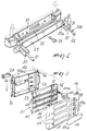
- the reference numeral 10 indicates the box of the button panel which, according to the installation requirements, may be mounted flush in a wall or simply fixed thereto, and the reference numeral 20 generally indicates a frame intended to frontally close the box 10 and constitute the actual button panel.
- Said frame 20 substantially comprises two parallel steel rods 21-22 which are sectioned or sectionable, at preset notches, in preset lengths corresponding to the number of the modular elements which will compose the button panel.
- each crosspiece is advantageously made of polymeric material of appropriate rigidity, such as ABS (acrylonitrile-butadienestyrene), and is provided with two spaced blocks 25-26 and respectively 27-28, intended to receive and retain, with a snap-together engagement, the corresponding lower and upper ends of the rods 21-22.
- each block 25-28 defines a cylindrical seat 30 (figure 2) and a longitudinal slot 31 extending parallel to the generatrices of the seat 30 and adjacent thereto; said slot has a smaller width than the diameter of said seat which in turn substantially corresponds to the diameter of the rods 21, 22.
- the latter are provided with inwardly protruding collars 30a adapted to co-operate with respective grooves 30b which are correspondingly formed in the ends of the rods.
- the lower crosspiece 23 is connected, by means of a hinge 32 with horizontal axis, to a base shoe 33 adapted to be rigidly associated with the box 10 by means of a screw 34 which engages in the threaded seat of a lower bracket 35 of the box.
- the frame 20 can be turned frontally forward and moved from a closure position, which is made stable by a second screw 36 which engages the threaded hole of an upper bracket 37 of the box, to an opening position preferably at least at 90° to the preceding one which allows access to a plurality of modular elements 40 which compose the button panel.
- Said elements 40 are fitted on the rods 21-22 so as to mutually superimpose, and each is composed of a front plate 41 intended to remain visible and by a rear housing 42 intended to accommodate the electromechanical componentry of each modular element.
- the front plate 41 is obtained by sectioning an extruded element made of aluminum or aluminum alloy and has a plurality of windows 43 for address cards, obtained by punching or equivalent methods, and a plurality of passages 43a for the buttons 44, formed to the side of the windows. Furthermore the plate 41 backwardly defines seats for the passage of the rods 21 and 22 of the frame 20 and has two curved lateral connecting wings 45 which delimit seats 46 for the accommodation and retention of elastomer gaskets 47 which ensure a seal between the box and the frame 20.
- the windows 43 are closed by respective transparent screens 48 provided with wings 48a which abut on the inner face of the plate 41.
- the respective address cards are visible through said screens and rest on corresponding raised portions 49 formed by an intermediate support 50 which also defines the holes 51 for accommodating the springs 52 of the buttons 44; said support 50 is made of transparent polymeric material and is inserted between the plate 41 and the housing 42.
- said housing supports a row of electric contacts 53, each of which is aligned with a corresponding button 44 and is closed by the button by means of a pusher finger 44a; said housing having a central window 54a intended to receive a lamp-holder shoe 54 and a series of connectors (not illustrated) or an equivalent terminal strip 55, which protrudes outside from the rear side of the housing and is electrically connected to the contacts 53.
- the housing 42 is removably associated with the plate 41 by means of four elastically resilient wings 56 which snap engage the undercut of a ridge 57 which delimits the seats of the rods 21-22.
- a ridge 58 is also defined on the plate 41 to align the plate 41 with the rear containment housing.
Landscapes
- Engineering & Computer Science (AREA)
- Power Engineering (AREA)
- Signal Processing (AREA)
- Telephone Set Structure (AREA)
- Casings For Electric Apparatus (AREA)
- Push-Button Switches (AREA)
Claims (8)
- Bedienungspult mit in Modulbauweise zusammensetzbaren Elementen, insbesondere für Haussprech- und Hausvideosprechstellensysteme, umfassend einen Rahmen (20), der zum frontalen Schließen eines kastenähnlichen Elementes (10) zum Einbau oder dergleichen vorgesehen ist, dadurch gekennzeichnet, daß der Rahmen ein Paar parallele Metallstäbe (21, 22) aufweist, die zum Aufnehmen einer Vielzahl von Modulelementen (40) geeignet sind, deren jedes eine Frontplatte (41) und eine hinteres Gehäuse (42) aufweist, das elektromechanische Bauteile enthält, wobei die Modulelemente (40) auf den Stäben angebracht sind, so daß sie übereinander angeordnet sind; wobei die Stäbe (21, 22) in unterschiedliche Längen unterteilt sind oder unterteilbar sind gemäß der Anzahl von Modulelementen, die, wenn sie übereinander angeordnet sind, das Bedienungspult bilden, wobei die Stäbe ferner durch untere und obere entfernbare Querstücke (23, 24) miteinander verbunden sind.
- Bedienungspult nach Anspruch 1, dadurch gekennzeichnet, daß das untere und obere Querstück (23, 24) des Rahmens aus Polymermaterial hergestellt sind, wobei jedes der Querstücke ein Paar in einem Abstand angeordnete Blöcke (25-28) trägt, die zum Aufnehmen und Halten entsprechender unterer und oberer Enden der Stäbe (21, 22) mit Schnappverbindung vorgesehen sind.
- Bedienungspult nach Anspruch 2, dadurch gekennzeichnet, daß jeder Block (25-28) der Querstücke (23, 24) einen zylindrischen Sitz (30) und einen angrenzenden Schlitz (31) definiert, der parallel zu den Mantellinien des Sitzes ist, wobei der Schlitz eine geringere Breite aufweist als der Durchmesser des Sitzes.
- Bedienungspult nach Anspruch 1, dadurch gekennzeichnet, daß das untere Querstück (23) des Rahmens (20) durch ein horizontales Achsgelenk (32) mit einer Ankerplatte (33) verbunden ist, die mit dem Kasten (10) starr verbunden sein kann, wobei das Gelenk (32) ermöglicht, daß der Rahmen von einer Schließposition, stabilisiert durch eine Verschlußschraube (36), in eine Frontöffnungsposition umgekippt werden kann, die bevorzugt mindestens 90° zu der vorhergehenden angeordnet ist.
- Bedienungspult nach einem der vorhergehenden Ansprüche, dadurch gekennzeichnet, daß die Frontplatte (41) jedes Modulelementes (40) aufweist: eine Vielzahl von abgedeckten Fenstern (43, 48) für Namenskarten und eine Vielzahl von nahe den Fenstern angeordneten Knöpfen (44), ein Paar in einem Abstand angeordneten zylindrischen Sitzen für den Durchtritt der Stäbe (21, 22) des Rahmens (20) und ein Paar gebogene seitliche Verbindungsflügel (45), die Sitze (46) zum Halten und Aufnehmen von Elastomerdichtungen (47) abgrenzen, die geeignet sind, eine Dichtung zwischen dem kastenähnlichen Element (10) und dem Rahmen (20) sicherzustellen.
- Bedienungspult nach den Ansprüchen 1 und 5, dadurch gekennzeichnet, daß die Frontplatte (41) jedes Modulelements (40) eine L-förmige Kante (47) aufweist, die die Durchtrittssitze der Stäbe (21, 22) abgrenzt und eine Unterschnittkupplung für eine Vielzahl von elastisch federnden Flügeln (56), die durch das hintere Gehäuse (42) des Modulelements (40) getragen sind, wobei die Frontplatte und das hintere Gehäuse in einem Schnappmechanismus lösbar verbunden sind.
- Bedienungspult nach einem der vorhergehenden Ansprüche, dadurch gekennzeichnet, daß jedes Modulelement (40) einen Zwischenträger (50) aus transparentem Polymermaterial zwischen der Frontplatte (41) und dem hinteren Gehäuse (42) eingesetzt aufweist, wobei der Zwischenträger (50) eine Vielzahl von erhabenen Bereichen (49) zum Stützen der Namenskarten und eine entsprechende Vielzahl von zylindrischen Sitzen (51) für die Aufnahme von Rückstellfedern (52) für die Knöpfe (44) definiert.
- Bedienungspult nach einem der vorhergehenden Ansprüche, dadurch gekennzeichnet, daß der Rücken jedes Modulelements (40) versehen ist mit einer Vielzahl von elektrischen Kontakten (53), wobei jeder Kontakt mit einem Drückerfinger (44a) des entsprechenden Knopfes fluchtet, mit einer Reihe von Verbindungsstücken oder einem äquivalenten Anschlußstreifen (55), die elektrisch mit den Kontakten (53) verbunden sind und von der Rückseite des Gehäuses (42) nach außen vorstehen, und mit einem Fenster (54a) zum Aufnehmen und Halten einer Lampenfassung (54).
Applications Claiming Priority (2)
| Application Number | Priority Date | Filing Date | Title |
|---|---|---|---|
| IT68028/88A IT1223916B (it) | 1988-11-18 | 1988-11-18 | Pulsantiera ad elementi modulari componibili particolarmente per impianti citofonici e videocitofonici |
| IT6802888 | 1988-11-18 |
Publications (3)
| Publication Number | Publication Date |
|---|---|
| EP0369403A2 EP0369403A2 (de) | 1990-05-23 |
| EP0369403A3 EP0369403A3 (de) | 1991-06-26 |
| EP0369403B1 true EP0369403B1 (de) | 1995-02-08 |
Family
ID=11307307
Family Applications (1)
| Application Number | Title | Priority Date | Filing Date |
|---|---|---|---|
| EP89121074A Expired - Lifetime EP0369403B1 (de) | 1988-11-18 | 1989-11-14 | Bedienungspult mit in Modulbauweise zusammensetzbaren Elementen, insbesondere für Tür- und Hausvideofernsprechstellen-Systeme |
Country Status (3)
| Country | Link |
|---|---|
| EP (1) | EP0369403B1 (de) |
| DE (1) | DE68921042T2 (de) |
| IT (1) | IT1223916B (de) |
Families Citing this family (6)
| Publication number | Priority date | Publication date | Assignee | Title |
|---|---|---|---|---|
| ES2109285T3 (es) * | 1991-03-19 | 1998-01-16 | Bitron Spa | Sistema para el montaje de un modulo de llamadas desde el exterior para un interfono audiovisual de inmuebles o viviendas. |
| DE19836435C1 (de) * | 1998-08-12 | 2000-01-13 | Loh Kg Ritto Werk | Türanlage, insbesondere Türsprechanlage |
| FR2790356B1 (fr) * | 1999-02-25 | 2001-05-04 | Schneider Electric Ind Sa | Dispositif de fixation d'un chassis dans un coffret d'appareillage electrique et coffret equipe d'un tel dispositif |
| ES1046897Y (es) * | 2000-08-02 | 2001-12-16 | Guinaz S L | Elemento portador de conjunto de pulsadores para placa de portero automatico. |
| ES1046891Y (es) * | 2000-08-02 | 2002-01-16 | Guinaz S L | Dispositivo de bisagra para placas de calle de porteros automaticos. |
| DE10340758A1 (de) * | 2003-09-02 | 2005-04-21 | Ritto Gmbh & Co Kg | Türstation mit Namensschilder und Klingeltasten |
Family Cites Families (4)
| Publication number | Priority date | Publication date | Assignee | Title |
|---|---|---|---|---|
| FR2248563A1 (en) * | 1973-10-17 | 1975-05-16 | Diela | Entry phone system for blocks of flats - has separate call button microphone and loud speaker units joined together |
| DE3214435C1 (de) * | 1982-04-20 | 1983-08-11 | Ritto-Werk Loh GmbH & Co KG, 6348 Herborn | Sprechstelle für eine Sprechanlage |
| DE3441446A1 (de) * | 1983-11-21 | 1985-05-30 | LT Terraneo S.p.A., Erba, Como | Schalttafel nach dem baukastensystem |
| ES2009616A6 (es) * | 1988-07-12 | 1989-10-01 | Gorrochategui Grajirena Javier | Sistema de placa botonera para porteros automaticos. |
-
1988
- 1988-11-18 IT IT68028/88A patent/IT1223916B/it active
-
1989
- 1989-11-14 DE DE68921042T patent/DE68921042T2/de not_active Expired - Fee Related
- 1989-11-14 EP EP89121074A patent/EP0369403B1/de not_active Expired - Lifetime
Also Published As
| Publication number | Publication date |
|---|---|
| DE68921042D1 (de) | 1995-03-23 |
| IT1223916B (it) | 1990-09-29 |
| IT8868028A0 (it) | 1988-11-18 |
| DE68921042T2 (de) | 1995-08-31 |
| EP0369403A2 (de) | 1990-05-23 |
| EP0369403A3 (de) | 1991-06-26 |
Similar Documents
| Publication | Publication Date | Title |
|---|---|---|
| US5600542A (en) | Modular automation device with a locking member | |
| US7112090B2 (en) | High density keystone jack patch panel | |
| US4875880A (en) | Modular faceplate system | |
| US6038126A (en) | Electrical power supply assembly | |
| US6186798B1 (en) | High density patching system | |
| CA2400829C (en) | Power distribution panel with modular elements | |
| US5312270A (en) | Wiring block having detachable leg assemblies | |
| US3764190A (en) | Lateral file | |
| NZ506301A (en) | Electromechanical contactor | |
| EP0369403B1 (de) | Bedienungspult mit in Modulbauweise zusammensetzbaren Elementen, insbesondere für Tür- und Hausvideofernsprechstellen-Systeme | |
| EP0070615B1 (de) | Aufnahmeeinleiten für Leiterplattenbaugruppen | |
| US5447367A (en) | Structure of vertical computer mainframe | |
| US5786987A (en) | Modular electrical interface device | |
| US20200366108A1 (en) | Charging Locker | |
| US5905631A (en) | Low-voltage switchgear assembly for the output or distribution of electrical energy | |
| US3511385A (en) | Frames for accommodating circuit cards or module frames | |
| US4443675A (en) | Multiple contact arrangement | |
| GB2284312A (en) | Modular electrical connector system | |
| US5519175A (en) | Electrical distribution equipment | |
| US3309577A (en) | Electrical component housing and system | |
| US4938351A (en) | Modular electrical component packaging system | |
| EP0351060B1 (de) | Bedienungspultsystem für Türsprechanlagen | |
| US6634692B1 (en) | Arrangement of equipment for a motor vehicle and dashboard comprising said arrangement | |
| US5108053A (en) | Mounting board, in particular for housings of the telecommunication and data technology | |
| US20070145864A1 (en) | Modular furniture system |
Legal Events
| Date | Code | Title | Description |
|---|---|---|---|
| PUAI | Public reference made under article 153(3) epc to a published international application that has entered the european phase |
Free format text: ORIGINAL CODE: 0009012 |
|
| AK | Designated contracting states |
Kind code of ref document: A2 Designated state(s): CH DE ES FR GB LI |
|
| PUAL | Search report despatched |
Free format text: ORIGINAL CODE: 0009013 |
|
| AK | Designated contracting states |
Kind code of ref document: A3 Designated state(s): CH DE ES FR GB LI |
|
| 17P | Request for examination filed |
Effective date: 19911004 |
|
| 17Q | First examination report despatched |
Effective date: 19930929 |
|
| GRAA | (expected) grant |
Free format text: ORIGINAL CODE: 0009210 |
|
| AK | Designated contracting states |
Kind code of ref document: B1 Designated state(s): CH DE ES FR GB LI |
|
| PG25 | Lapsed in a contracting state [announced via postgrant information from national office to epo] |
Ref country code: LI Effective date: 19950208 Ref country code: ES Free format text: THE PATENT HAS BEEN ANNULLED BY A DECISION OF A NATIONAL AUTHORITY Effective date: 19950208 Ref country code: CH Effective date: 19950208 |
|
| REF | Corresponds to: |
Ref document number: 68921042 Country of ref document: DE Date of ref document: 19950323 |
|
| REG | Reference to a national code |
Ref country code: CH Ref legal event code: PL |
|
| ET | Fr: translation filed | ||
| PG25 | Lapsed in a contracting state [announced via postgrant information from national office to epo] |
Ref country code: GB Effective date: 19951114 |
|
| PLBE | No opposition filed within time limit |
Free format text: ORIGINAL CODE: 0009261 |
|
| STAA | Information on the status of an ep patent application or granted ep patent |
Free format text: STATUS: NO OPPOSITION FILED WITHIN TIME LIMIT |
|
| 26N | No opposition filed | ||
| GBPC | Gb: european patent ceased through non-payment of renewal fee |
Effective date: 19951114 |
|
| PGFP | Annual fee paid to national office [announced via postgrant information from national office to epo] |
Ref country code: FR Payment date: 20041118 Year of fee payment: 16 |
|
| PGFP | Annual fee paid to national office [announced via postgrant information from national office to epo] |
Ref country code: DE Payment date: 20041215 Year of fee payment: 16 |
|
| PG25 | Lapsed in a contracting state [announced via postgrant information from national office to epo] |
Ref country code: DE Free format text: LAPSE BECAUSE OF NON-PAYMENT OF DUE FEES Effective date: 20060601 |
|
| PG25 | Lapsed in a contracting state [announced via postgrant information from national office to epo] |
Ref country code: FR Free format text: LAPSE BECAUSE OF NON-PAYMENT OF DUE FEES Effective date: 20060731 |
|
| REG | Reference to a national code |
Ref country code: FR Ref legal event code: ST Effective date: 20060731 |