EP0368453B1 - Distributor for internal combustion engine - Google Patents
Distributor for internal combustion engine Download PDFInfo
- Publication number
- EP0368453B1 EP0368453B1 EP89309346A EP89309346A EP0368453B1 EP 0368453 B1 EP0368453 B1 EP 0368453B1 EP 89309346 A EP89309346 A EP 89309346A EP 89309346 A EP89309346 A EP 89309346A EP 0368453 B1 EP0368453 B1 EP 0368453B1
- Authority
- EP
- European Patent Office
- Prior art keywords
- housing
- distributor
- internal combustion
- combustion engine
- connector
- Prior art date
- Legal status (The legal status is an assumption and is not a legal conclusion. Google has not performed a legal analysis and makes no representation as to the accuracy of the status listed.)
- Expired - Lifetime
Links
- 238000002485 combustion reaction Methods 0.000 title claims description 25
- 239000000463 material Substances 0.000 claims description 13
- 229920002379 silicone rubber Polymers 0.000 claims description 8
- 238000007789 sealing Methods 0.000 claims description 6
- 230000004907 flux Effects 0.000 claims description 3
- 230000006698 induction Effects 0.000 claims description 3
- 238000001514 detection method Methods 0.000 description 8
- 230000006872 improvement Effects 0.000 description 5
- 238000010276 construction Methods 0.000 description 3
- 239000004020 conductor Substances 0.000 description 2
- 229920001971 elastomer Polymers 0.000 description 2
- 230000005674 electromagnetic induction Effects 0.000 description 2
- 230000002708 enhancing effect Effects 0.000 description 2
- 239000012530 fluid Substances 0.000 description 2
- 230000020169 heat generation Effects 0.000 description 2
- 230000004048 modification Effects 0.000 description 2
- 238000012986 modification Methods 0.000 description 2
- 230000009467 reduction Effects 0.000 description 2
- 230000004308 accommodation Effects 0.000 description 1
- 230000008901 benefit Effects 0.000 description 1
- 239000000470 constituent Substances 0.000 description 1
- 230000000694 effects Effects 0.000 description 1
- 230000007613 environmental effect Effects 0.000 description 1
- 239000000945 filler Substances 0.000 description 1
- 230000017525 heat dissipation Effects 0.000 description 1
- 230000002093 peripheral effect Effects 0.000 description 1
- 230000001629 suppression Effects 0.000 description 1
- XLYOFNOQVPJJNP-UHFFFAOYSA-N water Substances O XLYOFNOQVPJJNP-UHFFFAOYSA-N 0.000 description 1
- 238000004804 winding Methods 0.000 description 1
Images




Classifications
-
- F—MECHANICAL ENGINEERING; LIGHTING; HEATING; WEAPONS; BLASTING
- F02—COMBUSTION ENGINES; HOT-GAS OR COMBUSTION-PRODUCT ENGINE PLANTS
- F02P—IGNITION, OTHER THAN COMPRESSION IGNITION, FOR INTERNAL-COMBUSTION ENGINES; TESTING OF IGNITION TIMING IN COMPRESSION-IGNITION ENGINES
- F02P7/00—Arrangements of distributors, circuit-makers or -breakers, e.g. of distributor and circuit-breaker combinations or pick-up devices
- F02P7/02—Arrangements of distributors, circuit-makers or -breakers, e.g. of distributor and circuit-breaker combinations or pick-up devices of distributors
-
- H—ELECTRICITY
- H01—ELECTRIC ELEMENTS
- H01F—MAGNETS; INDUCTANCES; TRANSFORMERS; SELECTION OF MATERIALS FOR THEIR MAGNETIC PROPERTIES
- H01F38/00—Adaptations of transformers or inductances for specific applications or functions
- H01F38/12—Ignition, e.g. for IC engines
-
- F—MECHANICAL ENGINEERING; LIGHTING; HEATING; WEAPONS; BLASTING
- F02—COMBUSTION ENGINES; HOT-GAS OR COMBUSTION-PRODUCT ENGINE PLANTS
- F02P—IGNITION, OTHER THAN COMPRESSION IGNITION, FOR INTERNAL-COMBUSTION ENGINES; TESTING OF IGNITION TIMING IN COMPRESSION-IGNITION ENGINES
- F02P7/00—Arrangements of distributors, circuit-makers or -breakers, e.g. of distributor and circuit-breaker combinations or pick-up devices
- F02P7/02—Arrangements of distributors, circuit-makers or -breakers, e.g. of distributor and circuit-breaker combinations or pick-up devices of distributors
- F02P7/021—Mechanical distributors
-
- F—MECHANICAL ENGINEERING; LIGHTING; HEATING; WEAPONS; BLASTING
- F02—COMBUSTION ENGINES; HOT-GAS OR COMBUSTION-PRODUCT ENGINE PLANTS
- F02P—IGNITION, OTHER THAN COMPRESSION IGNITION, FOR INTERNAL-COMBUSTION ENGINES; TESTING OF IGNITION TIMING IN COMPRESSION-IGNITION ENGINES
- F02P7/00—Arrangements of distributors, circuit-makers or -breakers, e.g. of distributor and circuit-breaker combinations or pick-up devices
- F02P7/02—Arrangements of distributors, circuit-makers or -breakers, e.g. of distributor and circuit-breaker combinations or pick-up devices of distributors
- F02P7/021—Mechanical distributors
- F02P7/026—Distributors combined with other ignition devices, e.g. coils, fuel-injectors
-
- F—MECHANICAL ENGINEERING; LIGHTING; HEATING; WEAPONS; BLASTING
- F02—COMBUSTION ENGINES; HOT-GAS OR COMBUSTION-PRODUCT ENGINE PLANTS
- F02P—IGNITION, OTHER THAN COMPRESSION IGNITION, FOR INTERNAL-COMBUSTION ENGINES; TESTING OF IGNITION TIMING IN COMPRESSION-IGNITION ENGINES
- F02P7/00—Arrangements of distributors, circuit-makers or -breakers, e.g. of distributor and circuit-breaker combinations or pick-up devices
- F02P7/02—Arrangements of distributors, circuit-makers or -breakers, e.g. of distributor and circuit-breaker combinations or pick-up devices of distributors
- F02P7/021—Mechanical distributors
- F02P7/026—Distributors combined with other ignition devices, e.g. coils, fuel-injectors
- F02P7/028—Distributors combined with other ignition devices, e.g. coils, fuel-injectors combined with circuit-makers or -breakers
-
- F—MECHANICAL ENGINEERING; LIGHTING; HEATING; WEAPONS; BLASTING
- F02—COMBUSTION ENGINES; HOT-GAS OR COMBUSTION-PRODUCT ENGINE PLANTS
- F02P—IGNITION, OTHER THAN COMPRESSION IGNITION, FOR INTERNAL-COMBUSTION ENGINES; TESTING OF IGNITION TIMING IN COMPRESSION-IGNITION ENGINES
- F02P7/00—Arrangements of distributors, circuit-makers or -breakers, e.g. of distributor and circuit-breaker combinations or pick-up devices
- F02P7/06—Arrangements of distributors, circuit-makers or -breakers, e.g. of distributor and circuit-breaker combinations or pick-up devices of circuit-makers or -breakers, or pick-up devices adapted to sense particular points of the timing cycle
- F02P7/061—Arrangements of distributors, circuit-makers or -breakers, e.g. of distributor and circuit-breaker combinations or pick-up devices of circuit-makers or -breakers, or pick-up devices adapted to sense particular points of the timing cycle pick-up devices without mechanical contacts
-
- F—MECHANICAL ENGINEERING; LIGHTING; HEATING; WEAPONS; BLASTING
- F02—COMBUSTION ENGINES; HOT-GAS OR COMBUSTION-PRODUCT ENGINE PLANTS
- F02P—IGNITION, OTHER THAN COMPRESSION IGNITION, FOR INTERNAL-COMBUSTION ENGINES; TESTING OF IGNITION TIMING IN COMPRESSION-IGNITION ENGINES
- F02P7/00—Arrangements of distributors, circuit-makers or -breakers, e.g. of distributor and circuit-breaker combinations or pick-up devices
- F02P7/06—Arrangements of distributors, circuit-makers or -breakers, e.g. of distributor and circuit-breaker combinations or pick-up devices of circuit-makers or -breakers, or pick-up devices adapted to sense particular points of the timing cycle
- F02P7/08—Arrangements of distributors, circuit-makers or -breakers, e.g. of distributor and circuit-breaker combinations or pick-up devices of circuit-makers or -breakers, or pick-up devices adapted to sense particular points of the timing cycle having air-tight casings
Definitions
- the present invention relates to a distributor employed in an electric ignition type multi-cylinder internal combustion engine and, more particularly, a distributor for an internal combustion engine which is improved in reliability and durability.
- a distributor for internal combustion engines comprises a housing, a shaft inserted in the housing to rotate synchronously with a crankshaft of an engine, a rotor head attached to an end of the shaft to distribute electric current, and a cap for closing the housing and having electrodes for inputting electric current to the rotor head and outputting distribution electric current.
- a distributor accommodates a signal detector and other electric devices inside the housing of the distributor in order to reduce the overall size of an internal combustion engine and dispose other devices in the spaces within the internal combustion engine.
- Japanese Patent Publication No. 45-26527/1970 is one example of this type of the distributors. It is necessary in order to accommodate various kinds of electric device inside the distributor housing to give special consideration to waterproofness, heat resistance, etc.
- One of the problems concerning waterproofness is that it is difficult for waterproofness and assembleability to be compatible with each other.
- the signal detector installed inside the housing is provided with a connector inserted in an opening formed in the side wall of the housing so as to project outside the housing.
- the connector is fixed to the housing by screws through an annular rubber gasket fitted on the connector.
- the above-mentioned structure for enhancing waterproofness also gives rise to a problem that dissipation of heat generated inside the housing is likely to be obstructed.
- the heat resistance of the ignition coil must be enhanced.
- a core of the ignition coil and the housing are in contact with each other through a seat, however, the area for heat transfer is relatively small and therefore dissipation of heat through conduction at the seat does not satisfactorily take place. Further, there is a problem of generation of heat from the ignition coil.
- a heat dissipating plate is provided between the signal detector and the housing and fastened to the housing together with the signal detector by means of fastening screws.
- one of the fastening screws is disposed in such a manner as to be inserted into the annular core, while the other screw is disposed outside the core.
- a short-circuit is formed by a part of the housing and the heat dissipating plate in such a manner as to surround the cross-section of the core (i.e., in such a manner as to link up with the annular core in the form of a chain), resulting in a short-circuit current flowing.
- the resistance component of the short-circuit which results in a reduction in the energy generated in the secondary winding of the ignition coil.
- part of the energy thus lost is consumed in the heat dissipating plate, thus causing an additional rise in temperature.
- An object of the present invention is to provide a distributor for internal combustion engines having superior assembleability and excellent waterproofness.
- a distributor for an internal combustion engine comprising a housing having a bottom, an open end and a side wall between said bottom and said open end, a shaft inserted in said housing to rotate synchronously with an engine crankshaft, a rotor head mounted on said shaft, a cap attached to said housing so as to cover said rotor head, and a signal detector accomodated in said housing and having a connector projecting outside said housing, characterized in that said housing has a cut-off portion formed in said side wall so as to extend toward said bottom of said housing from said open end for receiving said connector, and a gasket has a smaller part surrounding said connector and fitted in said cut-off portion of said housing and a larger part disposed on said open end pressed between said housing and said cap, whereby sealing around said connector and an abutment between said housing and said cap is formed.
- said larger part of said gasket is annularly shaped and said smaller part extends from a part of said larger part perpendicularly to a plane on which said larger part is disposed, said smaller part also being annularly shaped, and said connector is loosely inserted in said smaller part and pressed by said cap and said housing so that the connector is waterproofed.
- said cut-off portion has side faces which tend to converge from said open end toward said bottom, and said connector surrounded by said smaller part of said gasket is inserted in said cut-off portion and pressed to the bottom of said cut-off portion by said cap through said gasket.
- an electrical current path is formed by said housing and a heat release plate disposed in the housing around a part of an annular ignition coil core and means is provided for interrupting electric current flow in said current path.
- said means is an electrically insulating bushing disposed between said heat release plate and said housing.
- said electrical current path surrounds two magnetic flux paths of said core so that no induction current is induced in said electrical path, thereby providing said means for interrupting electric current flow in said electric current path.
- a material having good thermal conductivity is charged in the gap between the ignition coil and the housing.
- said material is a fluid silicon rubber which can be solidified.
- the distributor comprises a housing 30, a shaft 1 rotatably supported by the housing 30 through bearings 101, 102 and driven by a crankshaft (not shown), a signal rotor 3 mounted on the shaft 1, a rotor head 4 secured to a top end of the shaft 1 by means of a screw 401, a cap 6 fitted to the housing 30 to provide a space therein for accommodating therein various parts such as the rotor head 4, the signal rotor 3, etc. and a signal detection device or signal detector 5 accommodated in the housing 30.
- a sealing 103 is provided between the housing 30 and the shaft 1 for securing waterproof therebetween.
- the cap 6 has a central electrode 9 in contact with an electric conductor 402 of the rotor head 4 and a cap side electrode 10 facing an end of the electric conductor 402 with a gap.
- the signal detection device 5 includes a light emission element 501, a light receiving element 502 and a connector 5a and is fixed to the housing by screws. A light emitted from the light emission element is sent to the light receiving element through the signal rotor 3 so that the light is interrupted according to the rotation of the signal rotor 3 thereby to generate an ignition timing signal for the internal combustion engine. The signal is transferred to a control unit (not shown) through the connector 5a.
- the housing 30 comprises a bottom portion 303, and a side wall portion 304 extending perpendicular to the bottom portion 303.
- the side wall portion 304 has an open end 302 and a substantially rectangular opening that a part 30a of the side wall portion 304 is cut off.
- a notch 301 is formed at the open end 302 and a peripheral portion of the cut-off portion 30a for receiving a gasket 31.
- the gasket 31 is formed of a material having elasticity such as rubber, and has a large-diameter annular portion 31a having the same diameter as the notch of the housing 30 and a small-diameter annular portion 31b which extends perpendicularly to a plane on which the large-diameter annular portion 31a is disposed, and is to be mounted on the connector 5a and fitted in the notch of the cut-off portion 30a.
- the connector 5a having the small-diameter annular portion 31b of the gasket 31 fitted thereon is assembled into the housing 30 from the upper side as viewed in Fig. 2.
- the signal detector 5 is secured to the housing 30 by means of fastening screws 32 the gasket 31 is fitted in the notch 301 of the housing 30, and then the cap 6 is mounted on the gasket 31 and then fastened by fastening screws, whereby the gasket 31 is pressed on the housing 30 by an opening end face of the cap 6, and the cap 6 is sealingly secured to the housing 30, thus completing the assembly.
- the assembly is effected by a simple operation and sufficiently waterproofed.
- Fig. 3 shows a modification of a sealing part of the distributor.
- a cut-off portion 30a′ of the housing side wall has two sides thereof which are tapered in such a manner that the mouth of the cut-off portion 30a′ is wider than the bottom.
- the gasket has a large diameter portion 31a and small diameter portion 31b, and the small diameter portion 31b also has a similar shape to the cut-off portion 30a′. This construction enables to assemble the signal detection device having the gasket mounted on the connector into the housing.
- a distributor shown in Figs. 4a to 6 has an ignition coil 7 partially enclosed in a housing 2.
- the ignition coil 7 comprises an annular core 11, a coil 12 wound around a part of the core 11, and an electrode 8 electrically connected to the coil 12.
- the distributor also has a signal detection device 5 enclosed in the housing 2 in substantially the same manner as in Figs. 1 to 2. Between the housing 2 and the signal detection device 5, a heat release plate 21 is disposed through electrically insulated bushes 22 and secured to the housing 2 with means of screws 20, so that the heat release plate 21 is electrically isolated from the housing 2.
- the electrically insulating bushes 22 are not provided, a short circuit is established through the heat release plate 21 and the housing 2, as shown by S, and resistance heat due to electric current caused in the short circuit S by magnetic induction of the ignition coil 12 is generated.
- the electrically insulating bushes 22 provided in the short circuit S breaks the short circuit S so that no electric current flows in the short circuit S. This also contributes to heat reduction and provision of a reliable distributor.
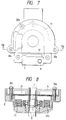
- a distributor shown in Figs. 7, 8 differs in that fastening screws for fastening the heat release plate 21 to the housing 2 are disposed outside the annular core 11 of the ignition coil 7 so that a short circuit through the heat release plate 21 and the housing 2 encloses two sections of the core 11, and in that the electrically insulating bushes 22 are not provided as mentioned above.
- the heat release plate 21 is secured outside the core 11.
- the core 11 is surrounded by electrically conductive members, the directions of two magnetic fluxes extending through the core 11 are opposite to each other in a cross-sectional view and, therefore, even if a short-circuit S′ is formed, no current can flow therein.
- a shaft 1 rotates synchronously with the rotation of an engine (not shown), so that an intermittent signal is generated by the signal rotor 3 as being a signal representative of a crank angle position of the engine and transferred to a controller (not shown) through the signal detector 5. Further, receiving an optimal engine ignition timing signal, the ignition coil 7 induces a high voltage. The induced high voltage is supplied to the rotor head 4 from the coil electrode 8 through a cap central electrode 9 and then discharged from the rotor head 4 toward a cap-side electrode 10, thus applying a high voltage to the ignition plug attached to each cylinder (not shown) of the engine.
- a material having a high thermal conductivity e.g., a silicon rubber
- a fluid material which can be solidified is conveniently employed.
- a material which has high electrical insulating properties is more preferable. From these points of view, silicon rubber is suitably employed.
- Fig. 10 shows a silicon rubber 15 charged in the gap between the ignition coil 7 and the housing 2.
- the silicon rubber 15 is filled between the housing 2 and the core 11 so as to enclose the core 11 in a U-shape.
- Fig. 11 shows a distributor in which an ignition coil is incorporated in the housing, and a heat release plate and electrically insulating bushes are provided.
- the rotor shaft 1 is mounted on the housing 2, and provided with a signal rotor 3 and a rotor head 4.
- the ignition coil 7 is disposed so that the core 11 surrounds the bearing portion of the shaft 1, and fixed to the housing 2 by fastening screws 14.
- the housing 2 has an open upper end at which a notch is formed for receiving a gasket 31 consisting of a large diameter portion and a small diameter portion as shown in Fig. 2, and a part of the side wall of the housing 2 is cut off as in Fig. 2 to form a cut-off portion 2a, the periphery of which is formed with a notch for receiving a part of the gasket 31 as in Fig. 2.
- the gasket 31 has a large-diameter portion fitted in the notch of the open upper end of the housing and a small-diameter portion extending perpendicularly to a place on which the large-diameter portion is disposed.
- the connector 5a of the signal detection device 5 is inserted, and the signal detection device 5 is mounted on the housing together with the gasket 31 after the heat release plate 21 and the electrically insulating bushes 22 are disposed and fastened by fastening screws.
- a cap 6 having a central electrode 9 and a side electrode is set on the gasket and is pressed by fastening screw 20a whereby sealing of the housing 2 is completed.
- a material 15 of excellent heat conductivity such as silicon rubber is inserted to release the heat generated in the ignition coil 7 through the material 15 and the side wall.
- the distributor for an internal combustion engine having a sealing means as disclosed in Figs. 1 to 3 has excellent assembleability and superior water tightness and hence it is possible to contribute to improvements in the reliability and durability of electric parts accommodated in the distributor.
- the distributor for an internal combustion engine makes it possible to prevent generation of heat due to the electromagnetic induction caused by the ignition coil and hence possible to contribute to improvements in the durability and reliability of electric parts accommodated in the distributor.
- the distributor for an internal combustion engine provided with the heat release plate in the manner as described above makes it possible to promote dissipation of heat generated from the ignition coil and hence possible to contribute to improvements in the reliability and durability of electric parts accommodated in the distributor by providing the material of excellent heat conductivity between the housing and the ignition coil.
- the invention enables improvements in the environmental resistance of electric parts accommodated in the distributor and exhibit the great practical advantage that it is possible to support the tendency in technological progress, i.e., accommodation of electric parts in the distributor in an intensive manner.
Landscapes
- Engineering & Computer Science (AREA)
- Chemical & Material Sciences (AREA)
- Combustion & Propulsion (AREA)
- Mechanical Engineering (AREA)
- General Engineering & Computer Science (AREA)
- Power Engineering (AREA)
- Ignition Installations For Internal Combustion Engines (AREA)
Description
- The present invention relates to a distributor employed in an electric ignition type multi-cylinder internal combustion engine and, more particularly, a distributor for an internal combustion engine which is improved in reliability and durability.
- In general, a distributor for internal combustion engines comprises a housing, a shaft inserted in the housing to rotate synchronously with a crankshaft of an engine, a rotor head attached to an end of the shaft to distribute electric current, and a cap for closing the housing and having electrodes for inputting electric current to the rotor head and outputting distribution electric current. Such a distributor accommodates a signal detector and other electric devices inside the housing of the distributor in order to reduce the overall size of an internal combustion engine and dispose other devices in the spaces within the internal combustion engine. Japanese Patent Publication No. 45-26527/1970 is one example of this type of the distributors. It is necessary in order to accommodate various kinds of electric device inside the distributor housing to give special consideration to waterproofness, heat resistance, etc.
- One of the problems concerning waterproofness is that it is difficult for waterproofness and assembleability to be compatible with each other.
- The signal detector installed inside the housing is provided with a connector inserted in an opening formed in the side wall of the housing so as to project outside the housing. The connector is fixed to the housing by screws through an annular rubber gasket fitted on the connector. However, this structure needs a large number of components and therefore suffers from inferior assembleability.
- The above-mentioned structure for enhancing waterproofness also gives rise to a problem that dissipation of heat generated inside the housing is likely to be obstructed. In a distributor where the ignition coil is accommodated inside a housing, the heat resistance of the ignition coil must be enhanced.
- However, the improvement in heat resistance that is attained simply by enhancing the heat resistance of the constituent material is limited and it is therefore necessary to improve heat resistance by contriving both suppression of heat generation and dissipation of heat.
- In a distributor housing an ignition coil, a core of the ignition coil and the housing are in contact with each other through a seat, however, the area for heat transfer is relatively small and therefore dissipation of heat through conduction at the seat does not satisfactorily take place. Further, there is a problem of generation of heat from the ignition coil.
- In order to increase the efficiency of dissipation of heat from electric devices, a heat dissipating plate is provided between the signal detector and the housing and fastened to the housing together with the signal detector by means of fastening screws.
- In this prior art, one of the fastening screws is disposed in such a manner as to be inserted into the annular core, while the other screw is disposed outside the core. Accordingly, a short-circuit is formed by a part of the housing and the heat dissipating plate in such a manner as to surround the cross-section of the core (i.e., in such a manner as to link up with the annular core in the form of a chain), resulting in a short-circuit current flowing. Thus, there is an energy loss due to the resistance component of the short-circuit, which results in a reduction in the energy generated in the secondary winding of the ignition coil. In addition, part of the energy thus lost is consumed in the heat dissipating plate, thus causing an additional rise in temperature.
- An object of the present invention is to provide a distributor for internal combustion engines having superior assembleability and excellent waterproofness.
- It is an advantageous feature of the present invention to provide a distributor wherein heat generation due to the electromagnetic induction in the ignition coil is prevented.
- According to this invention there is provided a distributor for an internal combustion engine comprising a housing having a bottom, an open end and a side wall between said bottom and said open end, a shaft inserted in said housing to rotate synchronously with an engine crankshaft, a rotor head mounted on said shaft, a cap attached to said housing so as to cover said rotor head, and a signal detector accomodated in said housing and having a connector projecting outside said housing, characterized in that said housing has a cut-off portion formed in said side wall so as to extend toward said bottom of said housing from said open end for receiving said connector, and a gasket has a smaller part surrounding said connector and fitted in said cut-off portion of said housing and a larger part disposed on said open end pressed between said housing and said cap, whereby sealing around said connector and an abutment between said housing and said cap is formed.
- Preferably, said larger part of said gasket is annularly shaped and said smaller part extends from a part of said larger part perpendicularly to a plane on which said larger part is disposed, said smaller part also being annularly shaped, and said connector is loosely inserted in said smaller part and pressed by said cap and said housing so that the connector is waterproofed.
- Conveniently, said cut-off portion has side faces which tend to converge from said open end toward said bottom, and said connector surrounded by said smaller part of said gasket is inserted in said cut-off portion and pressed to the bottom of said cut-off portion by said cap through said gasket.
- In such a construction, when the housing and the cap are secured to each other the connector is clamped between the cut-off portion and the cap whereas, when the cap is removed from the housing, the connector can be readily removed and attached through the cut-off portion. Thus, the assembly operation is facilitated.
- In a feature of this invention an electrical current path is formed by said housing and a heat release plate disposed in the housing around a part of an annular ignition coil core and means is provided for interrupting electric current flow in said current path.
- In one embodiment of the feature, said means is an electrically insulating bushing disposed between said heat release plate and said housing.
- In another embodiment of said feature said electrical current path surrounds two magnetic flux paths of said core so that no induction current is induced in said electrical path, thereby providing said means for interrupting electric current flow in said electric current path.
- Advantageously, a material having good thermal conductivity is charged in the gap between the ignition coil and the housing. Preferably, said material is a fluid silicon rubber which can be solidified. By filling the gap between the ignition coil and the housing with material having good thermal conductivity, so the transfer of heat from the ignition coil to the housing is promoted.
- Fig. 1 is a section view of an embodiment of a distributor for an internal combustion engine according to the present invention;
- Fig. 2 is a perspective view of parts used in the distributor as shown in Fig. 1;
- Fig. 3 is a front view showing a modification of a part of the distributor as shown in Figs. 1 and 2;
- Fig. 4a is a plane view of another embodiment of a distributor for an internal combustion engine according to the present invention;
- Fig. 4b is a perspective view of an ignition coil employed in the distributor shown in Fig. 4a;
- Fig. 5 is a section view of the distributor taken along a line V-V of Fig. 4a;
- Fig. 6 is an enlarged view of a part of the distributor shown in Fig. 5;
- Fig. 7 is a plane view of another embodiment of a distributor for an internal combustion engine according to the present invention;
- Fig. 8 is a sectional view of the distributor taken along a line VIII-VIII of Fig. 7;
- Fig. 9 is a sectional view of another embodiment of a distributor for an internal combustion engine according to the present invention;
- Fig. 10 is a perspective view of a part of the distributor in Fig. 9;
- Fig. 11 is a sectional view of another embodiment of a distributor according to the present invention.
- An embodiment of the present invention will be described hereunder in detail referring to Figs. 1 to 3.
- In Fig. 1 showing a distributor for an internal combustion engine, the distributor comprises a
housing 30, a shaft 1 rotatably supported by thehousing 30 throughbearings signal rotor 3 mounted on the shaft 1, arotor head 4 secured to a top end of the shaft 1 by means of ascrew 401, acap 6 fitted to thehousing 30 to provide a space therein for accommodating therein various parts such as therotor head 4, thesignal rotor 3, etc. and a signal detection device orsignal detector 5 accommodated in thehousing 30. Asealing 103 is provided between thehousing 30 and the shaft 1 for securing waterproof therebetween. Thecap 6 has acentral electrode 9 in contact with anelectric conductor 402 of therotor head 4 and acap side electrode 10 facing an end of theelectric conductor 402 with a gap. - The
signal detection device 5 includes alight emission element 501, alight receiving element 502 and aconnector 5a and is fixed to the housing by screws. A light emitted from the light emission element is sent to the light receiving element through thesignal rotor 3 so that the light is interrupted according to the rotation of thesignal rotor 3 thereby to generate an ignition timing signal for the internal combustion engine. The signal is transferred to a control unit (not shown) through theconnector 5a. - The
housing 30 comprises abottom portion 303, and aside wall portion 304 extending perpendicular to thebottom portion 303. Theside wall portion 304 has anopen end 302 and a substantially rectangular opening that apart 30a of theside wall portion 304 is cut off. Anotch 301 is formed at theopen end 302 and a peripheral portion of the cut-offportion 30a for receiving agasket 31. Thegasket 31 is formed of a material having elasticity such as rubber, and has a large-diameterannular portion 31a having the same diameter as the notch of thehousing 30 and a small-diameterannular portion 31b which extends perpendicularly to a plane on which the large-diameterannular portion 31a is disposed, and is to be mounted on theconnector 5a and fitted in the notch of the cut-offportion 30a. - The
connector 5a having the small-diameterannular portion 31b of thegasket 31 fitted thereon is assembled into thehousing 30 from the upper side as viewed in Fig. 2. Thesignal detector 5 is secured to thehousing 30 by means of fastening screws 32 thegasket 31 is fitted in thenotch 301 of thehousing 30, and then thecap 6 is mounted on thegasket 31 and then fastened by fastening screws, whereby thegasket 31 is pressed on thehousing 30 by an opening end face of thecap 6, and thecap 6 is sealingly secured to thehousing 30, thus completing the assembly. - As mentioned above, the assembly is effected by a simple operation and sufficiently waterproofed.
- Fig. 3 shows a modification of a sealing part of the distributor.
- A cut-off
portion 30a′ of the housing side wall has two sides thereof which are tapered in such a manner that the mouth of the cut-offportion 30a′ is wider than the bottom. The gasket has alarge diameter portion 31a andsmall diameter portion 31b, and thesmall diameter portion 31b also has a similar shape to the cut-offportion 30a′. This construction enables to assemble the signal detection device having the gasket mounted on the connector into the housing. - Another embodiment of the present invention will be described referring to Figs. 4a to 6.
- A distributor shown in Figs. 4a to 6 has an
ignition coil 7 partially enclosed in ahousing 2. As shown in Fig. 4b, theignition coil 7 comprises anannular core 11, acoil 12 wound around a part of the core 11, and anelectrode 8 electrically connected to thecoil 12. The distributor also has asignal detection device 5 enclosed in thehousing 2 in substantially the same manner as in Figs. 1 to 2. Between thehousing 2 and thesignal detection device 5, aheat release plate 21 is disposed through electrically insulatedbushes 22 and secured to thehousing 2 with means of screws 20, so that theheat release plate 21 is electrically isolated from thehousing 2. - In this construction, heat generated in various electric devices such as the
signal detection device 5, theignition coil 7 is relased through theheat release plate 21. - If the electrically insulating
bushes 22 are not provided, a short circuit is established through theheat release plate 21 and thehousing 2, as shown by S, and resistance heat due to electric current caused in the short circuit S by magnetic induction of theignition coil 12 is generated. However, in this embodiment, the electrically insulatingbushes 22 provided in the short circuit S breaks the short circuit S so that no electric current flows in the short circuit S. This also contributes to heat reduction and provision of a reliable distributor. - Further another embodiment of the present invention will be described referring to Figs. 7 and 8.
- A distributor shown in Figs. 7, 8 differs in that fastening screws for fastening the
heat release plate 21 to thehousing 2 are disposed outside theannular core 11 of theignition coil 7 so that a short circuit through theheat release plate 21 and thehousing 2 encloses two sections of the core 11, and in that the electrically insulatingbushes 22 are not provided as mentioned above. - In this embodiment, the
heat release plate 21 is secured outside thecore 11. In this arrangement, although thecore 11 is surrounded by electrically conductive members, the directions of two magnetic fluxes extending through the core 11 are opposite to each other in a cross-sectional view and, therefore, even if a short-circuit S′ is formed, no current can flow therein. - By virtue of this arrangement, it is unnecessary to provide the insulating
bush 22 as shown in Fig. 5 and theheat release plate 21 is secured directly to thehousing 2 at three points (or two or more points); therefore the heat release effect is enhanced. - Further another embodiment will be described hereunder in detail referring to Fig. 9.
- In Fig. 9, a shaft 1 rotates synchronously with the rotation of an engine (not shown), so that an intermittent signal is generated by the
signal rotor 3 as being a signal representative of a crank angle position of the engine and transferred to a controller (not shown) through thesignal detector 5. Further, receiving an optimal engine ignition timing signal, theignition coil 7 induces a high voltage. The induced high voltage is supplied to therotor head 4 from thecoil electrode 8 through a capcentral electrode 9 and then discharged from therotor head 4 toward a cap-side electrode 10, thus applying a high voltage to the ignition plug attached to each cylinder (not shown) of the engine. - When a high voltage is generated from the
ignition coil 7, heat is also generated simultaneously. - In order to transfer the generated heat to the
housing 2, a material having a high thermal conductivity (e.g., a silicon rubber) is charged in the gap between theignition coil 7 and thehousing 2. As the filler, a fluid material which can be solidified is conveniently employed. A material which has high electrical insulating properties is more preferable. From these points of view, silicon rubber is suitably employed. - Fig. 10 shows a
silicon rubber 15 charged in the gap between theignition coil 7 and thehousing 2. - As shown in Fig. 10, the
silicon rubber 15 is filled between thehousing 2 and the core 11 so as to enclose the core 11 in a U-shape. - Fig. 11 shows a distributor in which an ignition coil is incorporated in the housing, and a heat release plate and electrically insulating bushes are provided.
- In Fig. 11, the rotor shaft 1 is mounted on the
housing 2, and provided with asignal rotor 3 and arotor head 4. In thehousing 2, theignition coil 7 is disposed so that the core 11 surrounds the bearing portion of the shaft 1, and fixed to thehousing 2 by fastening screws 14. Thehousing 2 has an open upper end at which a notch is formed for receiving agasket 31 consisting of a large diameter portion and a small diameter portion as shown in Fig. 2, and a part of the side wall of thehousing 2 is cut off as in Fig. 2 to form a cut-offportion 2a, the periphery of which is formed with a notch for receiving a part of thegasket 31 as in Fig. 2. Thegasket 31 has a large-diameter portion fitted in the notch of the open upper end of the housing and a small-diameter portion extending perpendicularly to a place on which the large-diameter portion is disposed. In the small diameter portion of thegasket 31, theconnector 5a of thesignal detection device 5 is inserted, and thesignal detection device 5 is mounted on the housing together with thegasket 31 after theheat release plate 21 and the electrically insulatingbushes 22 are disposed and fastened by fastening screws. Acap 6 having acentral electrode 9 and a side electrode is set on the gasket and is pressed by fasteningscrew 20a whereby sealing of thehousing 2 is completed. In a gap formed between the side wall of thehousing 2 and theignition coil 7, amaterial 15 of excellent heat conductivity such as silicon rubber is inserted to release the heat generated in theignition coil 7 through thematerial 15 and the side wall. - The distributor for an internal combustion engine having a sealing means as disclosed in Figs. 1 to 3 has excellent assembleability and superior water tightness and hence it is possible to contribute to improvements in the reliability and durability of electric parts accommodated in the distributor.
- The distributor for an internal combustion engine makes it possible to prevent generation of heat due to the electromagnetic induction caused by the ignition coil and hence possible to contribute to improvements in the durability and reliability of electric parts accommodated in the distributor.
- The distributor for an internal combustion engine provided with the heat release plate in the manner as described above, makes it possible to promote dissipation of heat generated from the ignition coil and hence possible to contribute to improvements in the reliability and durability of electric parts accommodated in the distributor by providing the material of excellent heat conductivity between the housing and the ignition coil.
- Thus, the invention enables improvements in the environmental resistance of electric parts accommodated in the distributor and exhibit the great practical advantage that it is possible to support the tendency in technological progress, i.e., accommodation of electric parts in the distributor in an intensive manner.
Claims (8)
- A distributor for an internal combustion engine comprising a housing (30; 2) having a bottom (303), an open end (302) and a side wall (304) between said bottom (303) and said open end (302), a shaft (1) inserted in said housing (30; 2) to rotate synchronously with an engine crankshaft, a rotor head (4) mounted on said shaft (1), a cap (6) attached to said housing (30; 2) so as to cover said rotor head (4), and a signal detector (5) accomodated in said housing and having a connector (5a) projecting outside said housing (30; 2), characterized in that said housing (30; 2) has a cut-off portion (30a; 30a') formed in said side wall (304) so as to extend toward said bottom (303) of said housing (30; 2) from said open end (302) for receiving said connector (5a), and a gasket (31) has a smaller part (31b) surrounding said connector (5a) and fitted in said cut-off portion (30a; 30a') of said housing (30; 2) and a larger part (31a) disposed on said open end (302) pressed between said housing (30; 2) and said cap (6), whereby sealing around said connector (5a) and an abutment between said housing (30; 2) and said cap (6) is formed.
- A distributor for an internal combustion engine according to claim 1, wherein said larger part (31a) of said gasket (31) is annularly shaped and said smaller part (31b) extends from a part of said larger part (31a) perpendicularly to a plane on which said larger part (31a) is disposed, said smaller part (31b) also being annularly shaped, and said connector (5a) is loosely inserted in said smaller part (31b) and pressed by said cap (6) and said housing (30; 2) so that the connector (5a) is waterproofed.
- A distributor for an internal combustion engine according to claim 1, wherein said cut-off portion (30a') has side faces which tend to converge from said open end (302) toward said bottom (303), and said connector (5a) surrounded by said smaller part (31b) of said gasket (31) is inserted in said cut-off portion (30a') and pressed to the bottom of said cut-off portion (30a') by said cap (6) through said gasket (31).
- A distributor for an internal combustion engine according to claim 1, wherein an ignition coil (7) is arranged in the housing, and a material (15) having good thermal conductivity is charged in a gap between said housing (2) and the ignition coil (7).
- A distributor for an internal combustion engine according to claim 4, wherein said material (15) having good thermal conductivity is a silicon rubber having fluidity, said silicon rubber being poured and solidified in said gap.
- A distributor for an internal combustion engine according to any preceding claim, wherein an ignition coil (7) having an annular core (11) is arranged in the housing, and an electrical current path is formed by said housing (2) and a heat release plate (21) disposed in the housing (2) around a part of the annular ignition coil core (11), and means is provided for interrupting electric current flow in said current path.
- A distributor for an internal combustion engine according to claim 6, wherein said means for interrupting electric current flow is an electrically insulating bushing (22) disposed between said heat release plate (21) and said housing (2).
- A distributor for an internal combustion engine according to claim 6, wherein said electrical current path surrounds two magnetic flux paths of said core (11) so that no induction current is induced in said electrical path, thereby providing said means for interrupting electric current flow in said electric current path.
Applications Claiming Priority (2)
| Application Number | Priority Date | Filing Date | Title |
|---|---|---|---|
| JP232508/88 | 1988-09-19 | ||
| JP63232508A JPH0663498B2 (en) | 1988-09-19 | 1988-09-19 | Distributor for internal combustion engine |
Publications (2)
| Publication Number | Publication Date |
|---|---|
| EP0368453A1 EP0368453A1 (en) | 1990-05-16 |
| EP0368453B1 true EP0368453B1 (en) | 1994-04-13 |
Family
ID=16940431
Family Applications (1)
| Application Number | Title | Priority Date | Filing Date |
|---|---|---|---|
| EP89309346A Expired - Lifetime EP0368453B1 (en) | 1988-09-19 | 1989-09-14 | Distributor for internal combustion engine |
Country Status (5)
| Country | Link |
|---|---|
| US (1) | US4960099A (en) |
| EP (1) | EP0368453B1 (en) |
| JP (1) | JPH0663498B2 (en) |
| KR (1) | KR970011038B1 (en) |
| DE (1) | DE68914592T2 (en) |
Families Citing this family (8)
| Publication number | Priority date | Publication date | Assignee | Title |
|---|---|---|---|---|
| DE8814267U1 (en) * | 1988-11-15 | 1990-03-29 | Robert Bosch Gmbh, 7000 Stuttgart | Ignition distributor for internal combustion engines |
| JPH0752379Y2 (en) * | 1989-03-16 | 1995-11-29 | 三菱電機株式会社 | Distributor for internal combustion engine ignition |
| KR950000094Y1 (en) * | 1989-03-16 | 1995-01-09 | 미쓰비시덴키 가부시키가이샤 | Distributor for internal combustion engine |
| JP2533654B2 (en) * | 1989-10-18 | 1996-09-11 | 株式会社日立製作所 | Seal member used for internal combustion engine distributor |
| KR950000233B1 (en) * | 1990-09-28 | 1995-01-12 | 미쓰비시덴키 가부시키가이샤 | Distributor for ignition of internal combustion engine |
| JP2920242B2 (en) * | 1994-03-30 | 1999-07-19 | 三菱電機株式会社 | Switch for ignition of internal combustion engine |
| US6216679B1 (en) * | 1999-07-27 | 2001-04-17 | Delphi Technologies, Inc. | Ignition coil for an internal combustion engine |
| US9109568B2 (en) * | 2011-10-14 | 2015-08-18 | Moroso Performance Products, Inc. | Crank trigger distributor |
Family Cites Families (19)
| Publication number | Priority date | Publication date | Assignee | Title |
|---|---|---|---|---|
| GB1405011A (en) * | 1972-01-14 | 1975-09-03 | Lucas Electrical Co Ltd | Ignition distributors |
| US3888225A (en) * | 1973-09-26 | 1975-06-10 | Gen Motors Corp | Internal combustion engine ignition controller |
| DE2458593A1 (en) * | 1974-12-11 | 1976-06-16 | Bosch Gmbh Robert | CONNECTING DEVICE FOR DISTRIBUTOR |
| JPS5395442A (en) * | 1977-02-02 | 1978-08-21 | Hitachi Ltd | Fitting structure for non-contact igniter |
| US4129107A (en) * | 1977-08-22 | 1978-12-12 | General Motors Corporation | Magnetic pickup type ignition distributor |
| JPS54127939U (en) * | 1978-02-27 | 1979-09-06 | ||
| JPS56557A (en) * | 1979-06-12 | 1981-01-07 | Mitsubishi Electric Corp | Ignition distributor |
| AU522547B2 (en) * | 1980-01-23 | 1982-06-10 | Nippondenso Co. Ltd. | Ignition coil in distributor assembly |
| DE3039228A1 (en) * | 1980-10-17 | 1982-05-27 | Robert Bosch Gmbh, 7000 Stuttgart | IGNITION DISTRIBUTOR FOR INTERNAL COMBUSTION ENGINES |
| DE3109606A1 (en) * | 1981-03-13 | 1982-10-21 | Robert Bosch Gmbh, 7000 Stuttgart | Ignition distributor for internal-combustion engines |
| JPS5825580A (en) * | 1981-08-07 | 1983-02-15 | Nippon Denso Co Ltd | Ignition system with ignition coil integrating type ignition distributor |
| JPS5851065U (en) * | 1981-10-01 | 1983-04-06 | 三菱電機株式会社 | internal combustion engine ignition system |
| US4485796A (en) * | 1983-07-29 | 1984-12-04 | General Motors Corporation | Ignition distributor voltage generator |
| JPS60188875U (en) * | 1984-11-22 | 1985-12-14 | 三菱電機株式会社 | Ignition distributor |
| JPH0634623Y2 (en) * | 1985-05-09 | 1994-09-07 | 三菱電機株式会社 | Distributor for internal combustion engine |
| US4677946A (en) * | 1985-05-30 | 1987-07-07 | Ford Motor Company | Apparatus for positioning two sensor devices |
| JPH0821646B2 (en) * | 1986-04-04 | 1996-03-04 | 日本電気株式会社 | Method for forming integrated circuit cooling structure |
| JPS62247604A (en) * | 1987-02-02 | 1987-10-28 | Nippon Ferrite Ltd | Lumped constant type circulator and isolator |
| JPH0531267Y2 (en) * | 1987-11-09 | 1993-08-11 |
-
1988
- 1988-09-19 JP JP63232508A patent/JPH0663498B2/en not_active Expired - Fee Related
-
1989
- 1989-09-08 US US07/404,640 patent/US4960099A/en not_active Expired - Lifetime
- 1989-09-14 EP EP89309346A patent/EP0368453B1/en not_active Expired - Lifetime
- 1989-09-14 DE DE68914592T patent/DE68914592T2/en not_active Expired - Fee Related
- 1989-09-18 KR KR1019890013371A patent/KR970011038B1/en not_active Expired - Fee Related
Also Published As
| Publication number | Publication date |
|---|---|
| DE68914592D1 (en) | 1994-05-19 |
| JPH0663498B2 (en) | 1994-08-22 |
| KR900005067A (en) | 1990-04-13 |
| DE68914592T2 (en) | 1994-11-03 |
| KR970011038B1 (en) | 1997-07-05 |
| US4960099A (en) | 1990-10-02 |
| JPH0281957A (en) | 1990-03-22 |
| EP0368453A1 (en) | 1990-05-16 |
Similar Documents
| Publication | Publication Date | Title |
|---|---|---|
| EP0731550B1 (en) | AC generator for use in a vehicle | |
| US5109828A (en) | Apparatus for supplying high voltage to spark plug of internal combustion engine | |
| US4960099A (en) | Distributor for internal combustion engine | |
| US5359982A (en) | Ignitor for an internal combustion engine | |
| US4453526A (en) | Ignition system including ignition distributor integrated with ignition coil | |
| US4951641A (en) | Ignition coil assembly structure for an internal combustion engine | |
| KR100495364B1 (en) | Ignition Device for Internal Combustion Engines | |
| JPH09100771A (en) | Assembly of coil and spark plug | |
| US5139003A (en) | Distributor assembly for an internal combustion engine | |
| JP2864750B2 (en) | Ignition device for internal combustion engine | |
| JP4021132B2 (en) | Ignition device for internal combustion engine | |
| JPH0450461Y2 (en) | ||
| JP2744751B2 (en) | Switch for ignition of internal combustion engine | |
| JPS6018834B2 (en) | Ignition coil integrated ignition distributor | |
| JPS599100Y2 (en) | Interrupter cover for internal combustion engine ignition system | |
| US2250682A (en) | Gap connector in ignition generators | |
| JPS6145335Y2 (en) | ||
| JP4624394B2 (en) | Ignition coil device for internal combustion engine | |
| JPH06159211A (en) | Distributor for internal combustion engine ignition | |
| JPH06100175B2 (en) | Distributor with integrated ignition coil for internal combustion engine | |
| JPH06159212A (en) | Distributor for internal combustion engine ignition | |
| JPH11287175A (en) | Distributor for internal combustion engine and electromagnetic signal generator | |
| JPH06159214A (en) | Distributor for internal combustion engine ignition | |
| JPH0447169A (en) | Distributor for internal combustion engine | |
| JPH06341365A (en) | Distributor for internal combustion engine ignition |
Legal Events
| Date | Code | Title | Description |
|---|---|---|---|
| PUAI | Public reference made under article 153(3) epc to a published international application that has entered the european phase |
Free format text: ORIGINAL CODE: 0009012 |
|
| 17P | Request for examination filed |
Effective date: 19891009 |
|
| AK | Designated contracting states |
Kind code of ref document: A1 Designated state(s): DE FR GB |
|
| 17Q | First examination report despatched |
Effective date: 19920923 |
|
| GRAA | (expected) grant |
Free format text: ORIGINAL CODE: 0009210 |
|
| AK | Designated contracting states |
Kind code of ref document: B1 Designated state(s): DE FR GB |
|
| REF | Corresponds to: |
Ref document number: 68914592 Country of ref document: DE Date of ref document: 19940519 |
|
| ET | Fr: translation filed | ||
| PLBE | No opposition filed within time limit |
Free format text: ORIGINAL CODE: 0009261 |
|
| STAA | Information on the status of an ep patent application or granted ep patent |
Free format text: STATUS: NO OPPOSITION FILED WITHIN TIME LIMIT |
|
| 26N | No opposition filed | ||
| REG | Reference to a national code |
Ref country code: GB Ref legal event code: IF02 |
|
| PGFP | Annual fee paid to national office [announced via postgrant information from national office to epo] |
Ref country code: FR Payment date: 20020822 Year of fee payment: 14 |
|
| PGFP | Annual fee paid to national office [announced via postgrant information from national office to epo] |
Ref country code: GB Payment date: 20020827 Year of fee payment: 14 |
|
| PGFP | Annual fee paid to national office [announced via postgrant information from national office to epo] |
Ref country code: DE Payment date: 20020916 Year of fee payment: 14 |
|
| PG25 | Lapsed in a contracting state [announced via postgrant information from national office to epo] |
Ref country code: GB Free format text: LAPSE BECAUSE OF NON-PAYMENT OF DUE FEES Effective date: 20030914 |
|
| PG25 | Lapsed in a contracting state [announced via postgrant information from national office to epo] |
Ref country code: DE Free format text: LAPSE BECAUSE OF NON-PAYMENT OF DUE FEES Effective date: 20040401 |
|
| GBPC | Gb: european patent ceased through non-payment of renewal fee |
Effective date: 20030914 |
|
| PG25 | Lapsed in a contracting state [announced via postgrant information from national office to epo] |
Ref country code: FR Free format text: LAPSE BECAUSE OF NON-PAYMENT OF DUE FEES Effective date: 20040528 |
|
| REG | Reference to a national code |
Ref country code: FR Ref legal event code: ST |