EP0368446B1 - Self-calibrating accelerometer - Google Patents
Self-calibrating accelerometer Download PDFInfo
- Publication number
- EP0368446B1 EP0368446B1 EP89308436A EP89308436A EP0368446B1 EP 0368446 B1 EP0368446 B1 EP 0368446B1 EP 89308436 A EP89308436 A EP 89308436A EP 89308436 A EP89308436 A EP 89308436A EP 0368446 B1 EP0368446 B1 EP 0368446B1
- Authority
- EP
- European Patent Office
- Prior art keywords
- bridge
- resistor
- frame
- sensing mass
- acceleration sensor
- Prior art date
- Legal status (The legal status is an assumption and is not a legal conclusion. Google has not performed a legal analysis and makes no representation as to the accuracy of the status listed.)
- Expired - Lifetime
Links
- 230000001133 acceleration Effects 0.000 claims description 46
- 238000006073 displacement reaction Methods 0.000 claims description 41
- 230000008859 change Effects 0.000 claims description 17
- 230000004044 response Effects 0.000 claims description 8
- 239000004065 semiconductor Substances 0.000 claims description 6
- 239000004020 conductor Substances 0.000 claims description 5
- 230000035945 sensitivity Effects 0.000 claims description 5
- 230000005686 electrostatic field Effects 0.000 claims description 4
- 239000000463 material Substances 0.000 claims description 4
- 238000013016 damping Methods 0.000 claims description 3
- 238000000151 deposition Methods 0.000 claims description 3
- 238000004519 manufacturing process Methods 0.000 description 9
- XUIMIQQOPSSXEZ-UHFFFAOYSA-N Silicon Chemical compound [Si] XUIMIQQOPSSXEZ-UHFFFAOYSA-N 0.000 description 5
- 229910052710 silicon Inorganic materials 0.000 description 5
- 239000010703 silicon Substances 0.000 description 5
- 238000000034 method Methods 0.000 description 4
- XAGFODPZIPBFFR-UHFFFAOYSA-N aluminium Chemical compound [Al] XAGFODPZIPBFFR-UHFFFAOYSA-N 0.000 description 3
- 229910052782 aluminium Inorganic materials 0.000 description 3
- 239000011810 insulating material Substances 0.000 description 3
- 230000008569 process Effects 0.000 description 3
- 230000006870 function Effects 0.000 description 2
- 238000005259 measurement Methods 0.000 description 2
- 238000012360 testing method Methods 0.000 description 2
- RZVAJINKPMORJF-UHFFFAOYSA-N Acetaminophen Chemical compound CC(=O)NC1=CC=C(O)C=C1 RZVAJINKPMORJF-UHFFFAOYSA-N 0.000 description 1
- 238000012935 Averaging Methods 0.000 description 1
- ZOXJGFHDIHLPTG-UHFFFAOYSA-N Boron Chemical compound [B] ZOXJGFHDIHLPTG-UHFFFAOYSA-N 0.000 description 1
- 238000009825 accumulation Methods 0.000 description 1
- 230000002411 adverse Effects 0.000 description 1
- 229910052785 arsenic Inorganic materials 0.000 description 1
- -1 arsenic ions Chemical class 0.000 description 1
- 229910052796 boron Inorganic materials 0.000 description 1
- 230000003247 decreasing effect Effects 0.000 description 1
- 239000000428 dust Substances 0.000 description 1
- 230000000694 effects Effects 0.000 description 1
- 239000007943 implant Substances 0.000 description 1
- 150000002500 ions Chemical class 0.000 description 1
- 230000013011 mating Effects 0.000 description 1
- 239000012528 membrane Substances 0.000 description 1
- 230000004048 modification Effects 0.000 description 1
- 238000012986 modification Methods 0.000 description 1
- 239000002245 particle Substances 0.000 description 1
- 239000005297 pyrex Substances 0.000 description 1
- 239000000523 sample Substances 0.000 description 1
- 230000002277 temperature effect Effects 0.000 description 1
- 238000009966 trimming Methods 0.000 description 1
Images


Classifications
-
- G—PHYSICS
- G01—MEASURING; TESTING
- G01P—MEASURING LINEAR OR ANGULAR SPEED, ACCELERATION, DECELERATION, OR SHOCK; INDICATING PRESENCE, ABSENCE, OR DIRECTION, OF MOVEMENT
- G01P15/00—Measuring acceleration; Measuring deceleration; Measuring shock, i.e. sudden change of acceleration
-
- G—PHYSICS
- G01—MEASURING; TESTING
- G01P—MEASURING LINEAR OR ANGULAR SPEED, ACCELERATION, DECELERATION, OR SHOCK; INDICATING PRESENCE, ABSENCE, OR DIRECTION, OF MOVEMENT
- G01P21/00—Testing or calibrating of apparatus or devices covered by the preceding groups
-
- G—PHYSICS
- G01—MEASURING; TESTING
- G01P—MEASURING LINEAR OR ANGULAR SPEED, ACCELERATION, DECELERATION, OR SHOCK; INDICATING PRESENCE, ABSENCE, OR DIRECTION, OF MOVEMENT
- G01P15/00—Measuring acceleration; Measuring deceleration; Measuring shock, i.e. sudden change of acceleration
- G01P15/02—Measuring acceleration; Measuring deceleration; Measuring shock, i.e. sudden change of acceleration by making use of inertia forces using solid seismic masses
- G01P15/08—Measuring acceleration; Measuring deceleration; Measuring shock, i.e. sudden change of acceleration by making use of inertia forces using solid seismic masses with conversion into electric or magnetic values
- G01P15/0802—Details
-
- G—PHYSICS
- G01—MEASURING; TESTING
- G01P—MEASURING LINEAR OR ANGULAR SPEED, ACCELERATION, DECELERATION, OR SHOCK; INDICATING PRESENCE, ABSENCE, OR DIRECTION, OF MOVEMENT
- G01P15/00—Measuring acceleration; Measuring deceleration; Measuring shock, i.e. sudden change of acceleration
- G01P15/02—Measuring acceleration; Measuring deceleration; Measuring shock, i.e. sudden change of acceleration by making use of inertia forces using solid seismic masses
- G01P15/08—Measuring acceleration; Measuring deceleration; Measuring shock, i.e. sudden change of acceleration by making use of inertia forces using solid seismic masses with conversion into electric or magnetic values
- G01P15/12—Measuring acceleration; Measuring deceleration; Measuring shock, i.e. sudden change of acceleration by making use of inertia forces using solid seismic masses with conversion into electric or magnetic values by alteration of electrical resistance
-
- G—PHYSICS
- G01—MEASURING; TESTING
- G01P—MEASURING LINEAR OR ANGULAR SPEED, ACCELERATION, DECELERATION, OR SHOCK; INDICATING PRESENCE, ABSENCE, OR DIRECTION, OF MOVEMENT
- G01P15/00—Measuring acceleration; Measuring deceleration; Measuring shock, i.e. sudden change of acceleration
- G01P15/02—Measuring acceleration; Measuring deceleration; Measuring shock, i.e. sudden change of acceleration by making use of inertia forces using solid seismic masses
- G01P15/08—Measuring acceleration; Measuring deceleration; Measuring shock, i.e. sudden change of acceleration by making use of inertia forces using solid seismic masses with conversion into electric or magnetic values
- G01P15/12—Measuring acceleration; Measuring deceleration; Measuring shock, i.e. sudden change of acceleration by making use of inertia forces using solid seismic masses with conversion into electric or magnetic values by alteration of electrical resistance
- G01P15/123—Measuring acceleration; Measuring deceleration; Measuring shock, i.e. sudden change of acceleration by making use of inertia forces using solid seismic masses with conversion into electric or magnetic values by alteration of electrical resistance by piezo-resistive elements, e.g. semiconductor strain gauges
-
- G—PHYSICS
- G01—MEASURING; TESTING
- G01P—MEASURING LINEAR OR ANGULAR SPEED, ACCELERATION, DECELERATION, OR SHOCK; INDICATING PRESENCE, ABSENCE, OR DIRECTION, OF MOVEMENT
- G01P15/00—Measuring acceleration; Measuring deceleration; Measuring shock, i.e. sudden change of acceleration
- G01P15/02—Measuring acceleration; Measuring deceleration; Measuring shock, i.e. sudden change of acceleration by making use of inertia forces using solid seismic masses
- G01P15/08—Measuring acceleration; Measuring deceleration; Measuring shock, i.e. sudden change of acceleration by making use of inertia forces using solid seismic masses with conversion into electric or magnetic values
- G01P2015/0805—Measuring acceleration; Measuring deceleration; Measuring shock, i.e. sudden change of acceleration by making use of inertia forces using solid seismic masses with conversion into electric or magnetic values being provided with a particular type of spring-mass-system for defining the displacement of a seismic mass due to an external acceleration
- G01P2015/0822—Measuring acceleration; Measuring deceleration; Measuring shock, i.e. sudden change of acceleration by making use of inertia forces using solid seismic masses with conversion into electric or magnetic values being provided with a particular type of spring-mass-system for defining the displacement of a seismic mass due to an external acceleration for defining out-of-plane movement of the mass
- G01P2015/0825—Measuring acceleration; Measuring deceleration; Measuring shock, i.e. sudden change of acceleration by making use of inertia forces using solid seismic masses with conversion into electric or magnetic values being provided with a particular type of spring-mass-system for defining the displacement of a seismic mass due to an external acceleration for defining out-of-plane movement of the mass for one single degree of freedom of movement of the mass
- G01P2015/0828—Measuring acceleration; Measuring deceleration; Measuring shock, i.e. sudden change of acceleration by making use of inertia forces using solid seismic masses with conversion into electric or magnetic values being provided with a particular type of spring-mass-system for defining the displacement of a seismic mass due to an external acceleration for defining out-of-plane movement of the mass for one single degree of freedom of movement of the mass the mass being of the paddle type being suspended at one of its longitudinal ends
Definitions
- the instant invention relates to apparatus for sensing variations in the speed of an object, such as a motor vehicle, and microprocessor-controlled circuitry therefor to provide a calibrated output signal notwithstanding manufacturing tolerances and changes in sensor response due to changes in the operating environment thereof.
- EP-A-0261555 which forms the precharacterising portion of the annexed claim 1, discloses a semiconductor accelerometer in which a mass is supported by a cantilever, itself comprising strain gauges.
- FR-A-2421385 discloses an accelerometer in which a cantilevered mass may move, as a result of acceleration between two capacitive plates, the plates giving an electrostatic measurement of the movement.
- US 3120622 discloses an accelerometer, a piezoelectric element for measurement of acceleration and a piezoelectric or electromagnetic calibrating element.
- the prior art teaches sensors having a sensing mass cantilevered on a support beam which is displaced generally normal to the direction of beam extension by an accelerating force.
- a plurality of strain gages bonded to the beam or diffused into the surface thereof are connected to a Wheatstone bridge in a manner familiar to those skilled in the art, whereby an output proportional to the amount of such sensing mass displacement is obtained.
- the output from the strain gages is adversely affected by creep and hysteresis losses.
- the resistance of the strain gages and, hence, the output of the Wheatstone bridge connected thereto vary greatly with temperature.
- a further object of the instant invention is to provide control circuitry for an acceleration sensor which automatically Compensates for variations in sensor output due to variation in the manufacturing process therefor, thereby obviating extreme tolerance control in the sensor manufacturing process and eliminating the need for subsequent tailoring of the sensor control circuit to the specific characteristics of an individual sensor which was heretofore necessary in obtaining a proper mating of the sensor with the control circuit.
- an accelerometer comprising a rigid frame, a resilient beam extending from the frame, a sensing mass supported relative to the frame by the beam, the sensing mass being responsive to acceleration of the frame so as to be displaced thereby from an initial position relative to the frame towards a second position of maximum sensing mass displacement relative to the frame, whereby the beam is deflected a resistor on the beam, the resistance of the beam resistor varying in response to deflection of the beam, and an electrical circuit responsive to the resistance of the beam resistor, for generating an output signal characterised by means for electrostatically displacing the sensing mass to a third position intermediate the first and second positions without regard to acceleration,the output signal of the electrical circuit being calibratable by displacement of the sensing mass to the third position by the electrostatic displacement means.
- the center of mass of the sensing mass is displaced in a direction substantially normal to the plane of the beams from the initial position relative to the frame towards the second position relative thereto.
- Each of the supporting beams may have a plurality of resistors integral therewith whose resistance varies in response to deflection of the beams and, hence, in response to the displacement of the sensing mass.
- the beams may provide diametrical support for the sensing mass thereof.
- the means for electrostatically displacing the sensing mass from its initial position to a third position short of the second position thereof comprises layers of a non-magnetic electrically conductive material on opposed surfaces of the sensing mass and frame, respectively.
- the sensing mass is displaced to the third position by the resulting electrostatic field in a manner analogous to being displaced by a known accelerating field.
- the electrical circuit for generating a calibrated output signal from the instant sensor comprises a Wheatstone bridge having a pair of input and output terminals defining the four legs thereof, and a voltage source impressing a potential across the input terminals of the bridge.
- At least one of the legs of the bridge comprises a plurality of beam resistors.
- at least one of the legs of the bridge further comprises a variable-resistance resistor, the resistance of which is adjusted by suitable control means therefor, such as a microprocessor, whereby the range of voltages developed across the output terminals of the bridge is adjusted to compensate for changes in sensor operating temperature and to accommodate manufacturing tolerances.
- the electrical circuit may further comprise means for determining the voltage developed across the output terminals of the bridge, such as an analog-to-digital converter port on the microprocessor connected to the bridge output terminals by a differential amplifier; means for actuating the electrostatic displacement means of the instant sensor, such as a switch operable by the microprocessor for delivering the supply voltage across the layers; and means for generating a calibrated output signal derived from the instantaneous bridge output and adjusted to reflect changes in sensor response due to changes in the operating temperature thereof, as by comparing the instantaneous change in bridge output due to frame acceleration with the instantaneous change in bridge output due to electrostatic displacement of the sensing mass relative to the frame.
- a first exemplary embodiment 10 of the acceleration sensor of the instant invention comprises a frame 12 having a lower section, or base 14, formed of an insulating material such as pyrex and an upper section 16 formed of insulating material such as silicon secured to the upper surface 18 of the base 14 as by bonding therewith.
- a aperture 20 extends through the upper section 16 of the frame 12 from the upper surface 22 thereof so as to expose the upper surface 24 of the base 14.
- a thin, planar section 26 of a semiconductor material such as silicon is bonded to the upper surface 22 of the upper frame 16 so as to provide a pair of beams 28 which extend across the aperture 20 therein generally parallel to the upper surface 24 of the base 14.
- the planar section 26 and the sensing mass 30 are micromachined from a single block of semiconductor material such as silicon.
- the sensing mass 30 is thus free to be displaced from an initial position relative to the upper frame 16 towards a second position relative thereto in a direction substantially normal to the plane of the beams 28 in response to acceleration of the frame 12 in a direction opposite thereto.
- a plurality of protrusions or stops 34 and 35 project from the base 14 and upper frame 16, respectively, for limiting the amount of the displacement of the sensing mass 30 relative to the frame 12.
- the basal stop 34 thus defines the second position relative to the frame 12 to which the sensing mass 30 may be displaced by any given acceleration of the frame 12.
- the gap 36 between the sensing mass 30 and the frame 12 is suitably configured to provide the desired level of gas damping for the sensing mass 30.
- the instant sensor 10 further comprises a layer 40 of a non-magnetic electrically conductive material such as aluminum deposited as by a CVD process on the exposed upper surface 24 of the base 14.
- the conductive layer 40 on the base 14 thus extends generally parallel to the plane of the supporting beams 28 when the sensing mass 30 is in its initial position relative to the frame 12.
- a layer 42 of non-magnetic electrically conductive material such as aluminum is also deposited as by a CVD process on the underside 44 of the sensing mass 30 so as to be placed in opposition with the conductive layer 40 on the base 14.
- the layers 40 and 42 permit the electrostatic displacement of the sensing mass 30 relative to the frame 12 in the absence of an accelerating field upon the delivery of unlike electrical charges to the layers 40 and 42, respectively, as described hereinbelow.
- a pair of resistors 46 are formed integral with each beam 28, respectively, as by doping selected portions of the upper surface 48 of each beam 28.
- the beams may be doped with boron or arsenic ions using a CVD process or ion implant techniques.
- the resistance of the beam resistors 46 varies in response to beam deflection caused by displacement of the sensing mass 30 relative to the frame 12.
- the electrical circuit 50 for generating a calibrated output signal OUTPUT derived from the instantaneous resistance of the beam resistors 46 of the instant sensor 10 and adjusted for temperature effects thereon is shown schematically in FIG. 3.
- the electrical circuit 50 comprises a Wheatstone bridge 52; a voltage supply, such as a battery 54, which impresses a potential V S across the input terminals 56 and 58 of the bridge 52; a differential amplifier 60 connected to the output terminals 62 and 64 of the bridge 52 for amplifying the voltage V OUT developed thereacross; and a microprocessor 66 having a pair of analog-to-digital converter ports 68 thereon for reading the output of the differential amplifier 60 and the instantaneous amplitude of the supply voltage V S , and a plurality of output ports 70 thereon for controlling the range of voltages developed across the output terminals 62 and 64 of the bridge 52.
- the beam resistors 46 integral with the beams 28 of the sensor 10 are connected between the four terminals 56, 58, 62, and 64 of the Wheatstone bridge 52 to comprise the four legs 74, 76, 78, and 80 thereof.
- the position of each beam resistor 28 about the bridge 52 is determined in a manner known to those skilled in the art so as to maximize the change in the bridge output voltage V OUT upon displacement of the sensing mass 30 relative to the frame 12.
- a resistor 82 of variable resistance is placed in series with each beam resistor 28 in the two lower legs 78 and 80 of the bridge 52.
- the variable resistors 82 comprise resistors 84 of fixed resistance placed in series with the beam resistors 46 of legs 78 and 80, respectively, and a plurality of additional resistors 86 of fixed resistance which are switched under microprocessor control into parallel relation therewith, respectively.
- the switches operable by the microprocessor 66 for switching each additional resistor 86 in parallel with one of the series resistors 84 comprise a transistor 88, the emitter of which is connected to terminal 58 of the bridge 52 and the collector of which is connected to the additional resistor 86.
- the microprocessor 66 connects an additional resistor 86 into parallel relation with one of the series resistors 84 by delivering current from an output port 70 thereon to the base of the transistor 88 connected therewith.
- the microprocessor 66 is thus able to effect step changes in the resistance of legs 78 and 80 of the bridge 52 so as control the range of voltages developed across the output terminals 62 and 64 thereof during operation of the sensor 10.
- the electrical control circuit 50 compensates for changes in bridge output V OUT due to variations in sensor operating temperature, in addition to accommodating manufacturing tolerances in the nominal resistances of the beam resistors 46.
- the electrical control circuit 50 is able to limit the output V OUT of the bridge 52 to a range of voltages which will avoid saturation of the differential amplifier 60, even where the sensing mass 30 is maximally displaced by acceleration of the frame to the second position relative thereto, i.e., into engagement with the basal stop 34.
- the microprocessor 66 determines that the bridge output V OUT falls outside of the allowable range of values necessary to avoid saturation of the differential amplifier 60, the microprocessor 66 begins to sequentially connect the additional resistors 8 into parallel relation with series resistors 84 of legs 78 and 80, respectively, until the average bridge output V OUT once again falls within the allowable range.
- FIG. 3 shows only two switchable additional resistors 86 on each leg 78 and 80, the number of additional resistors 86 employed, and the resistance values thereof, are selected so as to provide optimum flexibility and performance.
- a purpose for tightly controlling of the output voltage V OUT of the bridge 52 is to permit the control circuit 50 to accurately determine when the acceleration input to the frame 12 exceeds a threshold value, whereupon the output OUTPUT from the control circuit 50 triggers an instrumentality, such as an air bag in a vehicle passenger restraint system (not shown).
- an instrumentality such as an air bag in a vehicle passenger restraint system (not shown).
- a second differential amplifier (not shown) having a different gain as the first differential amplifier 60 may be connected across the output terminals 62 and 64 of the bridge 52 to provide increased resolution with respect to that output range.
- a running average value of the microprocessor-adjusted and amplified bridge output (hereinafter referred to as V OUT for the sake of clarity) is thereafter used as the base-line for comparison with the instantaneous output V OUT,i of the bridge 52.
- V OUT the instantaneous changes in bridge output V OUT correspond to the displacement of the sensing mass 30 due to vehicle acceleration.
- a possible vehicle crash condition is indicated when the instantaneous bridge output V OUT,i exceeds the average bridge output V OUT by a threshold value, whereupon the microprocessor 66 assumes a crash condition and an average bridge output V OUT is no longer calculated.
- the average bridge output V OUT immediately prior to the indication of a possible crash condition is thereafter used as the base-line for comparison with the instantaneous output V OUT,i in order to further evaluate the vehicle acceleration profile. If the instantaneous output V OUT,i ceases to exceed the threshold value, a counter in the microprocessor is decremented. If the output does not exceed the threshold value for many consecutive readings, the microprocessor clears the crash condition by zeroing all accumulation counters therein, and normal averaging of the bridge output V OUT resumes.
- the microprocessor 66 is also provided with a plurality of output ports 70 thereon for controlling the delivery of the unlike electrical charges to the conductive layers 40 and 42 of the sensor 10, respectively, and for providing the calibrated output signal OUTPUT.
- the microprocessor 66 controls the delivery of unlike charges to the conductive layers 40 and 42 of the sensor 10 as by operating a switch 72 connecting the base layer 40 with the supply voltage V S (with the layer 42 on the sensing mass 30 already being permanently connected to ground).
- a schematic of an exemplary switch 72 connecting the base layer 40 with the supply voltage V S and operable by a pair of output ports 68 on the microprocessor 66 to apply two different potentials thereto is illustrated in FIG. 4.
- the electrical control circuit 50 of the instant invention utilizes the controlled electrostatic displacement of the sensing mass 30 relative to the sensor frame 12 to periodically recalibrate the output signal OUTPUT to accurately reflect the true acceleration profile of the vehicle.
- the instantaneous change in bridge output V OUT resulting from a known accelerating field is compared with the instantaneous change in bridge output V OUT upon electrostatic displacement of the sensing mass 30 by a known calibrating displacement voltage V D,c , at a constant calibrating temperature T c .
- the electrostatic field displacing the sensing mass 30 is thus effectively calibrated in terms of the known accelerating field, i.e., a unitary gravitational field.
- the instantaneous output V OUT,i of the bridge 52 may thereafter be periodically calibrated at any temperature T i by applying a like electrostatic deflection voltage V D,c across the conductive layers 40 and 42 of the sensor 10 and comparing the resultant change in bridge output V OUT with the earlier values therefor, as the sensing mass 30 is effectively being displaced by a known accelerating field.
- the instantaneous change in bridge output voltage V OUT,i due to the electrostatic displacement of the sensing mass 30 relative to the frame 12 appears to be a function of the electrostatic displacement voltage V D and otherwise constant sensor parameters. Accordingly, it is believed that the instantaneous electrostatic displacement voltage V D,i need not be equal to the original electrostatic displacement voltage V D,c for calibration of the instantaneous output V OUT,i of the bridge 52. Thus, the instant invention additionally avoids the costs encountered in otherwise having to tightly control the electrostatic displacement voltage V D . Accordingly, the instant invention employs simple switching means, such as the transistor/resistor circuit shown in FIG. 4, to provide a displacement voltage V D equal to either the supply voltage V S or a percentage thereof.
- a displacement voltage V D equal to the supply voltage V S is used to fully deflect the sensing mass 30 to the second position against the basal stop 34 to test for the presence of foreign objects, such as dust particles (not shown), in the gap 36 between the sensing mass 30 and the upper surface 24 of the base 14.
- a displacement voltage V D equal to a percentage of the supply voltage V S is used to partially displace the sensing mass 30 from its initial position relative to the frame 12 towards the second position relative thereto for calibration of the output signal OUTPUT.
- the microprocessor 66 reads the instantaneous electrostatic displacement voltage V D,i for use in calculating the equivalent accelerating field experienced by the sensing mass 30 during such electrostatic displacement thereof.
- the calibration of the instant sensor 10 and the generation of the calibrated output signal OUTPUT may be illustrated as follows: during sensor production, a circuit board (not shown) comprising the sensor 10 and the electrical control circuit 50 therefor is laid flat on a number of vertically extending probes in what is generally referred to as a "bed of nails" test, whereby various voltages about the circuit are measured to ensure circuit integrity.
- the sensing mass 30 is thus oriented so as to be subjected to the gravitational field of 1G and is displaced thereby from its initial position relative to the sensor frame 12 towards a second position relative thereto.
- the microprocessor 66 reads various locations in a non-volatile memory unit, such as an EEPROM (not shown), connected therewith.
- the microprocessor 66 reads the first calibrating output V OUT,c1 of the bridge 52 corresponding to the 1G acceleration field at the calibrating temperature T c , whereafter the microprocessor 66 stores the value of V OUT,c1 in the EEPROM.
- the circuit board is thereafter assembled into a housing (not shown) and potted therein, whereupon the circuit board is again tested at temperature T c to ensure sensor and circuit integrity.
- the housing is oriented in the position it will occupy when mounted in a vehicle, with the plane of the beams 28 supporting the sensing mass 30 thus extending substantially parallel with the gravitational field, whereby the sensing mass 30 returns to its initial position relative to the sensor frame 12.
- the microprocessor 66 checks the EEPROM for the presence of the first calibration value V OUT,c1 stored therein and further determines that all calibration constants have not yet been calculated.
- the microprocessor 66 then reads the second calibrating output V OUT,c2 of the bridge 52 in the absence of an accelerating field and at the calibration temperature T c .
- the difference between V OUT,c1 and V OUT,c2 is the calibrated "sensitivity" S c of the sensor 10, i.e., the change in bridge output V OUT due to an acceleration of 1G, at temperature T c
- the microprocessor 66 then actuates the switch 72 to apply a first calibrating displacement voltage V D,c to the conductive layers 40 and 42 of the sensor 10, whereby the sensing mass 30 is displaced electrostatically.
- the microprocessor 66 reads and stores the amplitude of the first calibrating displacement voltage V D,c and determines the change in bridge output V OUT by reading the resultant bridge output V OUT,D,c and subtracting there from the average output V OUT of the bridge 52, whereafter the resultant value is stored in the EEPROM.
- the accelerating field equivalent of the first calibrating electrostatic field is then calculated for use in interpreting instantaneous changes in bridge output V OUT .
- the equivalent field F c (in Gs) is calculated by the microprocessor 66 using the following formula: Where the instantaneous calibrating electrostatic deflection voltage V D,i equals the first calibrating electrostatic deflection voltage V D,c , the instantaneous sensitivity S i of the sensor 10, i.e., the instantaneous change in the bridge output voltage V OUT which corresponds to an acceleration of 1G, can be calculated as follows: Where the instantaneous calibrating electrostatic displacement voltage V D,i is not equal to the first calibrating electrostatic displacement voltage V D,c , the instantaneous sensitivity S i nonetheless remains a function of the electrostatically-induced instantaneous change in bridge output V OUT,D,i and the sensor calibration constants, with the precise relationship therebetween being established by suitable means.
- the first calibrating electrostatic voltage V D,c and the instantaneous calibrating electrostatic voltage V D,i are preferably chosen so as not to fully displace the sensing mass 30 towards the second position relative to the frame 12, i.e., into contact with the stop 34 protruding from the upper surface 24 of the base 14.
- the conductive layer 40 on the base 14 and the opposed conductive layer 42 on the sensing mass 30 may be normally biased to a like potential, e.g., to a nominal voltage of +5 volts.
- the sensing mass 30 is thereafter electrostatically displaced by increasing or decreasing the potential of either of the layers 40 or 42.
- FIGS. 5 and 6 show a second embodiment 90 of the acceleration sensor of the instant invention.
- the beams 28 provide diametrical support for the sensing mass 30 thereof.
- Each of the beams 28 is provided with at least one resistor 46 integral therewith.
- FIG. 6 shows a total of four beams 28 supporting the sensing mass 30, the instant invention contemplates the use of but two beams 28 to diametrically support the sensing mass 30.
- the instant invention further contemplates the use of a semiconductor "membrane" to support the sensing mass 30, selected portions of which are doped to provide a plurality of resistors 46 thereon.
- the beam resistors 46 of the second embodiment are connected between the terminals 56, 58, 62, and 64 of the Wheatstone bridge 52 in the manner known to those skilled in the art so as to maximize the change in output therefrom upon displacement of the sensing mass 30 relative to the frame 12.
Landscapes
- Physics & Mathematics (AREA)
- General Physics & Mathematics (AREA)
- Pressure Sensors (AREA)
Description
- The instant invention relates to apparatus for sensing variations in the speed of an object, such as a motor vehicle, and microprocessor-controlled circuitry therefor to provide a calibrated output signal notwithstanding manufacturing tolerances and changes in sensor response due to changes in the operating environment thereof.
- EP-A-0261555, which forms the precharacterising portion of the annexed
claim 1, discloses a semiconductor accelerometer in which a mass is supported by a cantilever, itself comprising strain gauges. - FR-A-2421385 discloses an accelerometer in which a cantilevered mass may move, as a result of acceleration between two capacitive plates, the plates giving an electrostatic measurement of the movement.
- US 3120622 discloses an accelerometer, a piezoelectric element for measurement of acceleration and a piezoelectric or electromagnetic calibrating element.
- The prior art teaches sensors having a sensing mass cantilevered on a support beam which is displaced generally normal to the direction of beam extension by an accelerating force. A plurality of strain gages bonded to the beam or diffused into the surface thereof are connected to a Wheatstone bridge in a manner familiar to those skilled in the art, whereby an output proportional to the amount of such sensing mass displacement is obtained. Unfortunately, the output from the strain gages is adversely affected by creep and hysteresis losses. Moreover, the resistance of the strain gages and, hence, the output of the Wheatstone bridge connected thereto vary greatly with temperature. The variation in bridge output due to temperature is further complicated, for example, where the sensing mass and its supporting beam are micromachined from silicon, as the relationship between the deflection of the sensing mass and temperature is unknown. Still further, such sensors are typically manufactured at high temperatures and subsequently cooled, whereby a thermal prestress is generated therein which is released or otherwise manifests itself as the operating temperature of the sensor varies. As a result, the sensor must be recalibrated on a continuing basis. Additionally, variations in the manufacturing process require additional manufacturing steps such as sensor resistance trimming which increase unit cost and reduce production volume.
- It is an object of the instant invention to provide an acceleration sensor and an electrical control circuit therefor which provides an output which remains unaffected by temperature changes in the operating environment thereof.
- A further object of the instant invention is to provide control circuitry for an acceleration sensor which automatically Compensates for variations in sensor output due to variation in the manufacturing process therefor, thereby obviating extreme tolerance control in the sensor manufacturing process and eliminating the need for subsequent tailoring of the sensor control circuit to the specific characteristics of an individual sensor which was heretofore necessary in obtaining a proper mating of the sensor with the control circuit.
- According to the present invention, there is provided an accelerometer comprising a rigid frame, a resilient beam extending from the frame, a sensing mass supported relative to the frame by the beam, the sensing mass being responsive to acceleration of the frame so as to be displaced thereby from an initial position relative to the frame towards a second position of maximum sensing mass displacement relative to the frame, whereby the beam is deflected a resistor on the beam, the resistance of the beam resistor varying in response to deflection of the beam, and an electrical circuit responsive to the resistance of the beam resistor, for generating an output signal characterised by means for electrostatically displacing the sensing mass to a third position intermediate the first and second positions without regard to acceleration,the output signal of the electrical circuit being calibratable by displacement of the sensing mass to the third position by the electrostatic displacement means.
- Preferably the center of mass of the sensing mass is displaced in a direction substantially normal to the plane of the beams from the initial position relative to the frame towards the second position relative thereto. Each of the supporting beams may have a plurality of resistors integral therewith whose resistance varies in response to deflection of the beams and, hence, in response to the displacement of the sensing mass. Where desired, the beams may provide diametrical support for the sensing mass thereof.
- Preferably, the means for electrostatically displacing the sensing mass from its initial position to a third position short of the second position thereof comprises layers of a non-magnetic electrically conductive material on opposed surfaces of the sensing mass and frame, respectively. Upon the delivery of unlike charges to the layers, respectively, the sensing mass is displaced to the third position by the resulting electrostatic field in a manner analogous to being displaced by a known accelerating field.
- Preferably the electrical circuit for generating a calibrated output signal from the instant sensor comprises a Wheatstone bridge having a pair of input and output terminals defining the four legs thereof, and a voltage source impressing a potential across the input terminals of the bridge. At least one of the legs of the bridge comprises a plurality of beam resistors. Additionally, at least one of the legs of the bridge further comprises a variable-resistance resistor, the resistance of which is adjusted by suitable control means therefor, such as a microprocessor, whereby the range of voltages developed across the output terminals of the bridge is adjusted to compensate for changes in sensor operating temperature and to accommodate manufacturing tolerances.
- The electrical circuit may further comprise means for determining the voltage developed across the output terminals of the bridge, such as an analog-to-digital converter port on the microprocessor connected to the bridge output terminals by a differential amplifier; means for actuating the electrostatic displacement means of the instant sensor, such as a switch operable by the microprocessor for delivering the supply voltage across the layers; and means for generating a calibrated output signal derived from the instantaneous bridge output and adjusted to reflect changes in sensor response due to changes in the operating temperature thereof, as by comparing the instantaneous change in bridge output due to frame acceleration with the instantaneous change in bridge output due to electrostatic displacement of the sensing mass relative to the frame.
- In the drawings, wherein like reference numerals are employed to designate like components among the various embodiments of the instant invention:
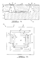
- FIG. 1 is a cross-sectional view of a first exemplary embodiment of the acceleration sensor of the instant invention;
- FIG. 2 is a bottom view of the first embodiment of the instant acceleration sensor with the base thereof removed;
- FIG. 3 is a diagrammatic schematic of an electrical circuit for generating a calibrated output signal from the instant acceleration sensor;
- FIG. 4 is a diagrammatic schematic of the microprocessor-controlled switch for depositing unlike charges on the opposed aluminum layers of the instant sensor, whereby the sensing mass of the sensor is electrostatically displaced relative to the frame thereof;
- FIG. 5 is a view in cross-section of a second exemplary embodiment of the instant acceleration sensor; and
- FIG. 6 is a bottom view of the second embodiment of the instant acceleration sensor with the base thereof removed.
- Referring to FIGS. 1 and 2, a first
exemplary embodiment 10 of the acceleration sensor of the instant invention comprises aframe 12 having a lower section, orbase 14, formed of an insulating material such as pyrex and anupper section 16 formed of insulating material such as silicon secured to theupper surface 18 of thebase 14 as by bonding therewith. Aaperture 20 extends through theupper section 16 of theframe 12 from theupper surface 22 thereof so as to expose theupper surface 24 of thebase 14. A thin,planar section 26 of a semiconductor material such as silicon is bonded to theupper surface 22 of theupper frame 16 so as to provide a pair ofbeams 28 which extend across theaperture 20 therein generally parallel to theupper surface 24 of thebase 14. A sensingmass 30, also micromachined from an insulating material such as silicon, is secured to thefree ends 32 of thebeams 28 as by bonding, whereby thesensing mass 30 is supported in a cantilevered fashion relative to theframe 12 by thebeams 28. Alternatively, theplanar section 26 and thesensing mass 30 are micromachined from a single block of semiconductor material such as silicon. - The sensing
mass 30 is thus free to be displaced from an initial position relative to theupper frame 16 towards a second position relative thereto in a direction substantially normal to the plane of thebeams 28 in response to acceleration of theframe 12 in a direction opposite thereto. A plurality of protrusions orstops base 14 andupper frame 16, respectively, for limiting the amount of the displacement of thesensing mass 30 relative to theframe 12. Thebasal stop 34 thus defines the second position relative to theframe 12 to which thesensing mass 30 may be displaced by any given acceleration of theframe 12. Thegap 36 between thesensing mass 30 and theframe 12 is suitably configured to provide the desired level of gas damping for thesensing mass 30. - The
instant sensor 10 further comprises alayer 40 of a non-magnetic electrically conductive material such as aluminum deposited as by a CVD process on the exposedupper surface 24 of thebase 14. Theconductive layer 40 on thebase 14 thus extends generally parallel to the plane of the supportingbeams 28 when thesensing mass 30 is in its initial position relative to theframe 12. Alayer 42 of non-magnetic electrically conductive material such as aluminum is also deposited as by a CVD process on theunderside 44 of thesensing mass 30 so as to be placed in opposition with theconductive layer 40 on thebase 14. Thelayers sensing mass 30 relative to theframe 12 in the absence of an accelerating field upon the delivery of unlike electrical charges to thelayers - A pair of
resistors 46 are formed integral with eachbeam 28, respectively, as by doping selected portions of the upper surface 48 of eachbeam 28. For example, the beams may be doped with boron or arsenic ions using a CVD process or ion implant techniques. The resistance of thebeam resistors 46 varies in response to beam deflection caused by displacement of thesensing mass 30 relative to theframe 12. - The
electrical circuit 50 for generating a calibrated output signal OUTPUT derived from the instantaneous resistance of thebeam resistors 46 of theinstant sensor 10 and adjusted for temperature effects thereon is shown schematically in FIG. 3. Theelectrical circuit 50 comprises a Wheatstonebridge 52; a voltage supply, such as abattery 54, which impresses a potential VS across theinput terminals bridge 52; adifferential amplifier 60 connected to theoutput terminals bridge 52 for amplifying the voltage VOUT developed thereacross; and amicroprocessor 66 having a pair of analog-to-digital converter ports 68 thereon for reading the output of thedifferential amplifier 60 and the instantaneous amplitude of the supply voltage VS, and a plurality ofoutput ports 70 thereon for controlling the range of voltages developed across theoutput terminals bridge 52. - More specifically, the
beam resistors 46 integral with thebeams 28 of thesensor 10 are connected between the fourterminals bridge 52 to comprise the fourlegs beam resistor 28 about thebridge 52 is determined in a manner known to those skilled in the art so as to maximize the change in the bridge output voltage VOUT upon displacement of thesensing mass 30 relative to theframe 12. - In addition, a
resistor 82 of variable resistance is placed in series with eachbeam resistor 28 in the twolower legs bridge 52. In the preferred embodiment of the instant invention, thevariable resistors 82 compriseresistors 84 of fixed resistance placed in series with thebeam resistors 46 oflegs additional resistors 86 of fixed resistance which are switched under microprocessor control into parallel relation therewith, respectively. The switches operable by themicroprocessor 66 for switching eachadditional resistor 86 in parallel with one of theseries resistors 84 comprise atransistor 88, the emitter of which is connected toterminal 58 of thebridge 52 and the collector of which is connected to theadditional resistor 86. Themicroprocessor 66 connects anadditional resistor 86 into parallel relation with one of theseries resistors 84 by delivering current from anoutput port 70 thereon to the base of thetransistor 88 connected therewith. - The
microprocessor 66 is thus able to effect step changes in the resistance oflegs bridge 52 so as control the range of voltages developed across theoutput terminals sensor 10. In this manner, theelectrical control circuit 50 compensates for changes in bridge output VOUT due to variations in sensor operating temperature, in addition to accommodating manufacturing tolerances in the nominal resistances of thebeam resistors 46. - Moreover, the
electrical control circuit 50 is able to limit the output VOUT of thebridge 52 to a range of voltages which will avoid saturation of thedifferential amplifier 60, even where thesensing mass 30 is maximally displaced by acceleration of the frame to the second position relative thereto, i.e., into engagement with thebasal stop 34. For example, when themicroprocessor 66 determines that the bridge output VOUT falls outside of the allowable range of values necessary to avoid saturation of thedifferential amplifier 60, themicroprocessor 66 begins to sequentially connect the additional resistors 8 into parallel relation withseries resistors 84 oflegs additional resistors 86 on eachleg additional resistors 86 employed, and the resistance values thereof, are selected so as to provide optimum flexibility and performance. - It is noted that a purpose for tightly controlling of the output voltage VOUT of the
bridge 52 is to permit thecontrol circuit 50 to accurately determine when the acceleration input to theframe 12 exceeds a threshold value, whereupon the output OUTPUT from thecontrol circuit 50 triggers an instrumentality, such as an air bag in a vehicle passenger restraint system (not shown). Thus, where a range of bridge output values is of particular significance, such as a bridge output VOUT approaching the threshold value, a second differential amplifier (not shown) having a different gain as the firstdifferential amplifier 60 may be connected across theoutput terminals bridge 52 to provide increased resolution with respect to that output range. In this regard, it is further noted that fewer switchableadditional resistors 86 are thus required on eachleg - A running average value of the microprocessor-adjusted and amplified bridge output (hereinafter referred to as VOUT for the sake of clarity) is thereafter used as the base-line for comparison with the instantaneous output VOUT,i of the
bridge 52. Where theinstant sensor 10 is utilized in a vehicle passenger restraint system as an acceleration sensor therefor, the instantaneous changes in bridge output VOUT correspond to the displacement of the sensingmass 30 due to vehicle acceleration. A possible vehicle crash condition is indicated when the instantaneous bridge output VOUT,i exceeds the average bridge output VOUT by a threshold value, whereupon themicroprocessor 66 assumes a crash condition and an average bridge output VOUT is no longer calculated. The average bridge output VOUT immediately prior to the indication of a possible crash condition is thereafter used as the base-line for comparison with the instantaneous output VOUT,i in order to further evaluate the vehicle acceleration profile. If the instantaneous output VOUT,i ceases to exceed the threshold value, a counter in the microprocessor is decremented. If the output does not exceed the threshold value for many consecutive readings, the microprocessor clears the crash condition by zeroing all accumulation counters therein, and normal averaging of the bridge output VOUT resumes. - The
microprocessor 66 is also provided with a plurality ofoutput ports 70 thereon for controlling the delivery of the unlike electrical charges to theconductive layers sensor 10, respectively, and for providing the calibrated output signal OUTPUT. - The
microprocessor 66 controls the delivery of unlike charges to theconductive layers sensor 10 as by operating aswitch 72 connecting thebase layer 40 with the supply voltage VS (with thelayer 42 on thesensing mass 30 already being permanently connected to ground). A schematic of anexemplary switch 72 connecting thebase layer 40 with the supply voltage VS and operable by a pair ofoutput ports 68 on themicroprocessor 66 to apply two different potentials thereto is illustrated in FIG. 4. - With respect to the generation of a calibrated output signal OUTPUT from the
sensor 10, theelectrical control circuit 50 of the instant invention utilizes the controlled electrostatic displacement of the sensingmass 30 relative to thesensor frame 12 to periodically recalibrate the output signal OUTPUT to accurately reflect the true acceleration profile of the vehicle. More specifically, during initial calibration of thesensor 10 and the associatedcontrol circuitry 50 therefor, the instantaneous change in bridge output VOUT resulting from a known accelerating field, as by temporarily orienting thesensor 10 so that thebeams 28 thereof extend substantially perpendicular to the earth's gravitational field, is compared with the instantaneous change in bridge output VOUT upon electrostatic displacement of the sensingmass 30 by a known calibrating displacement voltage VD,c, at a constant calibrating temperature Tc. The electrostatic field displacing the sensingmass 30 is thus effectively calibrated in terms of the known accelerating field, i.e., a unitary gravitational field. The instantaneous output VOUT,i of thebridge 52 may thereafter be periodically calibrated at any temperature Ti by applying a like electrostatic deflection voltage VD,c across theconductive layers sensor 10 and comparing the resultant change in bridge output VOUT with the earlier values therefor, as the sensingmass 30 is effectively being displaced by a known accelerating field. - Still further, the instantaneous change in bridge output voltage VOUT,i due to the electrostatic displacement of the sensing
mass 30 relative to theframe 12 appears to be a function of the electrostatic displacement voltage VD and otherwise constant sensor parameters. Accordingly, it is believed that the instantaneous electrostatic displacement voltage VD,i need not be equal to the original electrostatic displacement voltage VD,c for calibration of the instantaneous output VOUT,i of thebridge 52. Thus, the instant invention additionally avoids the costs encountered in otherwise having to tightly control the electrostatic displacement voltage VD. Accordingly, the instant invention employs simple switching means, such as the transistor/resistor circuit shown in FIG. 4, to provide a displacement voltage VD equal to either the supply voltage VS or a percentage thereof. Specifically, a displacement voltage VD equal to the supply voltage VS is used to fully deflect thesensing mass 30 to the second position against thebasal stop 34 to test for the presence of foreign objects, such as dust particles (not shown), in thegap 36 between the sensingmass 30 and theupper surface 24 of thebase 14. A displacement voltage VD equal to a percentage of the supply voltage VS is used to partially displace thesensing mass 30 from its initial position relative to theframe 12 towards the second position relative thereto for calibration of the output signal OUTPUT. Where the instantaneous electrostatic displacement voltage VD,i differs from the original calibrating displacement voltage VD,c, themicroprocessor 66 reads the instantaneous electrostatic displacement voltage VD,i for use in calculating the equivalent accelerating field experienced by the sensingmass 30 during such electrostatic displacement thereof. - The calibration of the
instant sensor 10 and the generation of the calibrated output signal OUTPUT may be illustrated as follows: during sensor production, a circuit board (not shown) comprising thesensor 10 and theelectrical control circuit 50 therefor is laid flat on a number of vertically extending probes in what is generally referred to as a "bed of nails" test, whereby various voltages about the circuit are measured to ensure circuit integrity. The sensingmass 30 is thus oriented so as to be subjected to the gravitational field of 1G and is displaced thereby from its initial position relative to thesensor frame 12 towards a second position relative thereto. When power is first delivered to the circuit board, themicroprocessor 66 reads various locations in a non-volatile memory unit, such as an EEPROM (not shown), connected therewith. If these values are zero, the sensor has not yet been calibrated, and themicroprocessor 66 reads the first calibrating output VOUT,c1 of thebridge 52 corresponding to the 1G acceleration field at the calibrating temperature Tc, whereafter themicroprocessor 66 stores the value of VOUT,c1 in the EEPROM. - The circuit board is thereafter assembled into a housing (not shown) and potted therein, whereupon the circuit board is again tested at temperature Tc to ensure sensor and circuit integrity. The housing is oriented in the position it will occupy when mounted in a vehicle, with the plane of the
beams 28 supporting the sensingmass 30 thus extending substantially parallel with the gravitational field, whereby the sensingmass 30 returns to its initial position relative to thesensor frame 12. Themicroprocessor 66 checks the EEPROM for the presence of the first calibration value VOUT,c1 stored therein and further determines that all calibration constants have not yet been calculated. Themicroprocessor 66 then reads the second calibrating output VOUT,c2 of thebridge 52 in the absence of an accelerating field and at the calibration temperature Tc. The difference between VOUT,c1 and VOUT,c2 is the calibrated "sensitivity" Sc of thesensor 10, i.e., the change in bridge output VOUT due to an acceleration of 1G, at temperature Tc. - With the
sensor 10 still at the calibration temperature Tc, themicroprocessor 66 then actuates theswitch 72 to apply a first calibrating displacement voltage VD,c to theconductive layers sensor 10, whereby the sensingmass 30 is displaced electrostatically. Themicroprocessor 66 reads and stores the amplitude of the first calibrating displacement voltage VD,c and determines the change in bridge output VOUT by reading the resultant bridge output VOUT,D,c and subtracting there from the average output VOUT of thebridge 52, whereafter the resultant value is stored in the EEPROM. - The accelerating field equivalent of the first calibrating electrostatic field is then calculated for use in interpreting instantaneous changes in bridge output VOUT. Specifically, the equivalent field Fc (in Gs) is calculated by the
microprocessor 66 using the following formula:
Where the instantaneous calibrating electrostatic deflection voltage VD,i equals the first calibrating electrostatic deflection voltage VD,c, the instantaneous sensitivity Si of thesensor 10, i.e., the instantaneous change in the bridge output voltage VOUT which corresponds to an acceleration of 1G, can be calculated as follows:
Where the instantaneous calibrating electrostatic displacement voltage VD,i is not equal to the first calibrating electrostatic displacement voltage VD,c, the instantaneous sensitivity Si nonetheless remains a function of the electrostatically-induced instantaneous change in bridge output VOUT,D,i and the sensor calibration constants, with the precise relationship therebetween being established by suitable means. - It is noted that the first calibrating electrostatic voltage VD,c and the instantaneous calibrating electrostatic voltage VD,i (where the latter differs from the former) are preferably chosen so as not to fully displace the
sensing mass 30 towards the second position relative to theframe 12, i.e., into contact with thestop 34 protruding from theupper surface 24 of thebase 14. Additionally, it is noted that, under the instant invention, theconductive layer 40 on thebase 14 and the opposedconductive layer 42 on thesensing mass 30 may be normally biased to a like potential, e.g., to a nominal voltage of +5 volts. The sensingmass 30 is thereafter electrostatically displaced by increasing or decreasing the potential of either of thelayers - FIGS. 5 and 6 show a
second embodiment 90 of the acceleration sensor of the instant invention. In thesecond embodiment 90, thebeams 28 provide diametrical support for thesensing mass 30 thereof. Each of thebeams 28 is provided with at least oneresistor 46 integral therewith. It is noted that, while FIG. 6 shows a total of fourbeams 28 supporting the sensingmass 30, the instant invention contemplates the use of but twobeams 28 to diametrically support the sensingmass 30. Similarly, the instant invention further contemplates the use of a semiconductor "membrane" to support the sensingmass 30, selected portions of which are doped to provide a plurality ofresistors 46 thereon. It is noted that thebeam resistors 46 of the second embodiment are connected between theterminals Wheatstone bridge 52 in the manner known to those skilled in the art so as to maximize the change in output therefrom upon displacement of the sensingmass 30 relative to theframe 12. - While the preferred embodiments of the invention have been disclosed, it should be appreciated that the invention is susceptible of modification without departing from the scope of the subjoined claims.
Claims (20)
- An accelerometer comprising:
a rigid frame (12);
a resilient beam (26) extending from said frame (12);
a sensing mass (30) supported relative to said frame (12) by said beam (28), said sensing mass (30) being responsive to acceleration of said frame (12) so as to be displaced thereby from an initial position relative to said frame (12) towards a second position of maximum sensing mass displacement relative to said frame (12), whereby said beam (28) is deflected;
a resistor (46) on said beam (28), the resistance of said beam resistor (46) varying in response to deflection of said beam (28); and
an electrical circuit (Figure 3) responsive to the resistance of said beam resistor (46) for generating an output signal; characterised by
means (40,42) for electrostatically displacing said sensing mass (30) to a third position intermediate said first and second positions without regard to acceleration;
said output signal of said electrical circuit being calibratable by displacement of said sensing mass (30) to said third position by said electrostatic displacement means (40, 42). - The acceleration sensor of claim 1, wherein said beam (28) is formed of a semiconductor material, and said beam resistor (46) comprises a doped portion of said semiconductor material.
- The acceleration sensor of claim 1 or 2 wherein said electrostatic displacement means comprises;
a first layer of non-magnetic electrically conductive material (40) on said frame;
a second layer of non-magnetic electrically conductive material (42) on said sensing mass (30) in opposition with said first layer (40) on said frame (12); and
means for depositing unlike electrical charges on said first (40) and second (42) layers, respectively. - The acceleration sensor of claim 3 wherein said means for depositing unlike electrical charges (72) on said first (40) and second (42) layers, respectively, comprises a voltage source (Vs) switchably connected across said layers.
- The acceleration sensor of any preceding claim including stop means (34) for limiting the amount of displacement of said sensing mass (30) relative to said frame (12).
- The acceleration sensor of claim 5 wherein said stop means (34) comprises a plurality of protrusions from said frame engageable with said sensing mass (30).
- The acceleration sensor of any preceding claim including a second resilient beam (28) extending from said frame (12) to support said sensing mass (30), said beams (28) providing diametrical support for said sensing mass (30).
- The acceleration sensor of any preceding claim including gas damping means for damping displacement of said sensing mass (30).
- The acceleration sensor of any preceding claim wherein said electrical circuit comprises:
a Wheatstone bridge (52) having a pair of input terminals (56,58) and a pair of output terminals (62,64) defining the four legs thereof, at least one of said legs comprising a beam resistor (46);
means (54) for impressing a potential across the input terminals (56,58) of said bridge; and
means (66) for determining the voltage developed across the output terminals (62,64) of said bridge. - The acceleration sensor of claim 9 wherein said means for determining the voltage developed across the output terminals of said bridge comprises a microprocessor (66) having means thereon connected to each of the output terminals, respectively, for reading the voltage developed thereacross.
- The acceleration sensor of claim 10 wherein said means on said microprocessor (66) for reading the voltage developed across the output terminals of said bridge comprises an analog-to-digital converter port (68) on said microprocessor (66) connected to the output terminals by a differential amplifier (60).
- The acceleration sensor of claim 10 or 11 wherein at least one of said legs of said bridge further comprises a first resistor of variable resistance (82), the resistance of said first resistor (82) being controlled by said microprocessor (66).
- The acceleration sensor of claim 12 wherein said first resistor (82) is placed in series with a beam resistor (46) between the terminals defining said leg of said bridge.
- The acceleration sensor of claim 12 wherein said first resistor (82) of variable resistance comprises a second resistor (84) of fixed resistance and at least one addition resistor (86) of fixed resistance, the or each said additional resistor (86) being switchable in parallel with said second resistor (84) by a like number of switch means operable by said microprocessor (66).
- The acceleration sensor of claim 14 wherein each of said switch means operable by said microprocessor (66) for switching one of said additional resistors (86) in parallel with said second resistor (84) comprises a transistor (88), the emitter of said transistor being connected to a terminal of said bridge; the collector of said transistor (88) being connected to said additional resistor (86), and the base of said transistor being connected to said microprocessor (66), whereby said additional resistor (86) is switchably connected in parallel with said second resistor (84) upon the delivery of current to the base of said transistor (88) by said microprocessor (66).
- The acceleration sensor of any one of claims 9 to 15 wherein said electrical circuit further comprises:
means for actuating said electrostatic displacement means (40,42);
means for determining the resultant change in the voltage developed across the output terminals (62,64) of said bridge (52); and
means for generating a calibrated output signal derived from the instantaneous voltage developed across the output terminals (62,64) of said bridge (52). - The acceleration sensor of any one of claims 10 to 15 wherein said means for generating said calibrated output signal comprises means for comparing the change in the voltage developed across the output terminals (62,64) of said bridge (52) due to acceleration of said sensing mass (30) relative to said frame (12) with the change in the voltage developed across the output terminals (62,64) of said bridge (52) due to the electrostatic displacement of said sensing mass (30) relative to said frame (12).
- The acceleration sensor of claim 16 wherein said means for generating said calibrated output signal comprises
means for determining the instantaneous sensitivity of said sensor (46) by comparing the instantaneous change in the voltage developed across the output terminals (62,64) of said bridge (52) due to acceleration of said sensing mass (30) relative to said frame (12) with the change in the voltage developed across the output terminals (62,64) of said bridge (52) due to the electrostatic displacement of said sensing mass (30) relative to said frame (12); and
means for calibrating the instantaneous voltage developed across the output terminals (62,64) of said bridge (52) in terms of said instantaneous sensitivity. - The accelerometer of any preceding claim, wherein said the means for electrostatically displacing the sensing means providing an electrostatic field which is calibrated with reference to a unitary gravitational field.
- The accelerometer of claim 17 including means responsive to the voltage developed across the output terminals (62,64) of said bridge (52) for varying the resistance of one of the legs of said bridge (52), whereby the voltage developed across the output terminals (62,64) of said bridge (52) is maintained in a desired range.
Applications Claiming Priority (2)
| Application Number | Priority Date | Filing Date | Title |
|---|---|---|---|
| US24836288A | 1988-09-23 | 1988-09-23 | |
| US248362 | 1988-09-23 |
Related Child Applications (2)
| Application Number | Title | Priority Date | Filing Date |
|---|---|---|---|
| EP19930100645 Division EP0542719A3 (en) | 1988-09-23 | 1989-08-21 | A method for establishing a value for the sensitivity of an acceleration sensor |
| EP93100645.6 Division-Into | 1993-01-18 |
Publications (3)
| Publication Number | Publication Date |
|---|---|
| EP0368446A2 EP0368446A2 (en) | 1990-05-16 |
| EP0368446A3 EP0368446A3 (en) | 1990-10-31 |
| EP0368446B1 true EP0368446B1 (en) | 1993-11-10 |
Family
ID=22938766
Family Applications (2)
| Application Number | Title | Priority Date | Filing Date |
|---|---|---|---|
| EP89308436A Expired - Lifetime EP0368446B1 (en) | 1988-09-23 | 1989-08-21 | Self-calibrating accelerometer |
| EP19930100645 Ceased EP0542719A3 (en) | 1988-09-23 | 1989-08-21 | A method for establishing a value for the sensitivity of an acceleration sensor |
Family Applications After (1)
| Application Number | Title | Priority Date | Filing Date |
|---|---|---|---|
| EP19930100645 Ceased EP0542719A3 (en) | 1988-09-23 | 1989-08-21 | A method for establishing a value for the sensitivity of an acceleration sensor |
Country Status (6)
| Country | Link |
|---|---|
| EP (2) | EP0368446B1 (en) |
| JP (1) | JPH0766010B2 (en) |
| KR (1) | KR940008199B1 (en) |
| AU (2) | AU624172B2 (en) |
| CA (1) | CA1330265C (en) |
| DE (1) | DE68910641T2 (en) |
Families Citing this family (34)
| Publication number | Priority date | Publication date | Assignee | Title |
|---|---|---|---|---|
| JP2681215B2 (en) * | 1989-05-29 | 1997-11-26 | 株式会社ワコー | Method for manufacturing sensor using laminated substrate |
| JPH03134552A (en) * | 1989-10-20 | 1991-06-07 | Hitachi Ltd | Detection device with self-calibration function |
| DE69019343T2 (en) | 1989-12-28 | 1996-02-15 | Wako Kk | Acceleration sensors. |
| US6864677B1 (en) | 1993-12-15 | 2005-03-08 | Kazuhiro Okada | Method of testing a sensor |
| US5412986A (en) * | 1990-12-21 | 1995-05-09 | Texas Instruments Incorporated | Accelerometer with improved strain gauge sensing means |
| JPH04258175A (en) * | 1991-02-12 | 1992-09-14 | Mitsubishi Electric Corp | Manufacture of silicon semiconductor acceleration sensor |
| DE69124377T2 (en) * | 1991-03-30 | 1997-06-12 | Kazuhiro Okada | Accelerometer with self test |
| US5345822A (en) * | 1991-06-28 | 1994-09-13 | Murata Manufacturing Co., Ltd. | Vibratory gyroscope having a support member |
| JP2737481B2 (en) * | 1991-10-02 | 1998-04-08 | 日本電気株式会社 | Semiconductor acceleration sensor |
| JP2773495B2 (en) * | 1991-11-18 | 1998-07-09 | 株式会社日立製作所 | 3D acceleration sensor |
| JPH05215769A (en) * | 1992-02-06 | 1993-08-24 | Nec Corp | Semiconductor acceleration sensor |
| US5665915A (en) * | 1992-03-25 | 1997-09-09 | Fuji Electric Co., Ltd. | Semiconductor capacitive acceleration sensor |
| JP2831195B2 (en) * | 1992-03-25 | 1998-12-02 | 富士電機株式会社 | Semiconductor acceleration sensor |
| GB2266151B (en) * | 1992-03-25 | 1996-09-11 | Fuji Electric Co Ltd | Semiconductor acceleration sensor |
| FR2694403B1 (en) * | 1992-07-31 | 1994-10-07 | Sagem | Pendulum electrostatic accelerometer with test electrode and method of manufacturing such an accelerometer. |
| JP2999088B2 (en) * | 1993-04-28 | 2000-01-17 | 株式会社日立製作所 | Airbag system |
| JP2549815B2 (en) * | 1993-06-03 | 1996-10-30 | 富士通テン株式会社 | Semiconductor acceleration sensor and test method thereof |
| IT1267374B1 (en) * | 1994-01-28 | 1997-02-05 | Marelli Autronica | SELF-CALIBRATION DEVICE OF A BRIDGE SENSOR. |
| JPH08122359A (en) * | 1994-10-21 | 1996-05-17 | Fuji Electric Co Ltd | Semiconductor acceleration sensor and its manufacturing method and test method |
| US6084257A (en) * | 1995-05-24 | 2000-07-04 | Lucas Novasensor | Single crystal silicon sensor with high aspect ratio and curvilinear structures |
| US6316796B1 (en) * | 1995-05-24 | 2001-11-13 | Lucas Novasensor | Single crystal silicon sensor with high aspect ratio and curvilinear structures |
| FR2736723B1 (en) * | 1995-07-12 | 1997-09-19 | Sagem | PENDULUM ACCELEROMETER WITH CAPACITIVE TEST ACTUATOR |
| US5596144A (en) * | 1995-08-04 | 1997-01-21 | Delco Electronics Corporation | Piezoresistive force rebalance accelerometer |
| US5721162A (en) * | 1995-11-03 | 1998-02-24 | Delco Electronics Corporation | All-silicon monolithic motion sensor with integrated conditioning circuit |
| US5665899A (en) * | 1996-02-23 | 1997-09-09 | Rosemount Inc. | Pressure sensor diagnostics in a process transmitter |
| US6347541B1 (en) * | 1998-06-29 | 2002-02-19 | Continental Teves, Inc. | Two-point calibration of a longitudinal acceleration sensor |
| JP4367165B2 (en) * | 2004-02-13 | 2009-11-18 | 株式会社デンソー | Inspection method of semiconductor mechanical quantity sensor |
| DE102004030380B4 (en) * | 2004-06-23 | 2010-07-29 | Eads Deutschland Gmbh | Micromechanical pressure sensor and method for self-testing of such |
| ITTO20070335A1 (en) | 2007-05-15 | 2008-11-16 | Sequoia It S R L | WIDE BAND ACCELEROMETER WITH SELF-RECOGNITION OF CALIBRATION |
| DE102007057136A1 (en) * | 2007-11-28 | 2009-06-04 | Robert Bosch Gmbh | Circuit for a micromechanical structure-borne sound sensor and method for operating a micromechanical structure-borne sound sensor |
| CN105518470B (en) * | 2013-09-09 | 2020-08-18 | 罗伯特·博世有限公司 | Vibration sensor and sensitivity adjustment method thereof |
| JP6513519B2 (en) * | 2015-07-17 | 2019-05-15 | 株式会社日立製作所 | Physical quantity sensor |
| WO2019190504A1 (en) | 2018-03-28 | 2019-10-03 | Halliburton Energy Services, Inc. | In-situ calibration of borehole gravimeters |
| CN112014596B (en) * | 2019-05-30 | 2022-10-28 | 武汉杰开科技有限公司 | Accelerometer and manufacturing method thereof |
Family Cites Families (8)
| Publication number | Priority date | Publication date | Assignee | Title |
|---|---|---|---|---|
| US3120622A (en) * | 1960-03-29 | 1964-02-04 | Gulton Ind Inc | Self-calibrating accelerometer |
| FR2421385A1 (en) * | 1978-03-29 | 1979-10-26 | Singer Co | Electrostatic type accelerometer with digital output - has electrodes operating as restoring mechanism and signal generators in conjunction with pendulum |
| CH642573A5 (en) * | 1979-09-24 | 1984-04-30 | Gw Maschinen Ag | METHOD AND DEVICE FOR CHECKING BANDEROLATED BODIES. |
| US4611304A (en) * | 1983-07-27 | 1986-09-09 | Sundstrand Data Control, Inc. | Transducer memory circuit |
| EP0261555B1 (en) * | 1986-09-22 | 1992-07-08 | Nippondenso Co., Ltd. | Semiconductor accelerometer |
| JPS6385461A (en) * | 1986-09-30 | 1988-04-15 | Aisin Seiki Co Ltd | Calibrating method for acceleration sensor and acceleration sensor |
| DE3717677C1 (en) * | 1987-05-26 | 1988-12-22 | Bayerische Motoren Werke Ag | Method for calibrating acceleration pick-ups (sensors), and device for carrying out the method |
| US4827091A (en) * | 1988-09-23 | 1989-05-02 | Automotive Systems Laboratory, Inc. | Magnetically-damped, testable accelerometer |
-
1989
- 1989-08-21 EP EP89308436A patent/EP0368446B1/en not_active Expired - Lifetime
- 1989-08-21 EP EP19930100645 patent/EP0542719A3/en not_active Ceased
- 1989-08-21 CA CA000608910A patent/CA1330265C/en not_active Expired - Fee Related
- 1989-08-21 DE DE89308436T patent/DE68910641T2/en not_active Expired - Fee Related
- 1989-08-23 AU AU40171/89A patent/AU624172B2/en not_active Ceased
- 1989-08-31 KR KR1019890012485A patent/KR940008199B1/en not_active Expired - Fee Related
- 1989-09-22 JP JP1245408A patent/JPH0766010B2/en not_active Expired - Lifetime
-
1992
- 1992-12-01 AU AU29774/92A patent/AU644547B2/en not_active Expired - Fee Related
Also Published As
| Publication number | Publication date |
|---|---|
| EP0368446A2 (en) | 1990-05-16 |
| AU644547B2 (en) | 1993-12-09 |
| DE68910641D1 (en) | 1993-12-16 |
| AU624172B2 (en) | 1992-06-04 |
| KR940008199B1 (en) | 1994-09-08 |
| CA1330265C (en) | 1994-06-21 |
| JPH02116755A (en) | 1990-05-01 |
| AU2977492A (en) | 1993-02-18 |
| JPH0766010B2 (en) | 1995-07-19 |
| EP0542719A3 (en) | 1993-06-02 |
| EP0542719A2 (en) | 1993-05-19 |
| EP0368446A3 (en) | 1990-10-31 |
| AU4017189A (en) | 1990-03-29 |
| KR900005178A (en) | 1990-04-13 |
| DE68910641T2 (en) | 1994-04-28 |
Similar Documents
| Publication | Publication Date | Title |
|---|---|---|
| US5060504A (en) | Self-calibrating accelerometer | |
| EP0368446A2 (en) | Self-calibrating accelerometer | |
| US5163325A (en) | Self-compensating accelerometer | |
| US5465604A (en) | Method for adjusting sensitivity of a sensor | |
| US5103667A (en) | Self-testable micro-accelerometer and method | |
| KR0175300B1 (en) | Detection device with self calibration | |
| US5253510A (en) | Self-testable micro-accelerometer | |
| US4941354A (en) | Tri-axial accelerometers | |
| US5481905A (en) | Transducer circuit having negative integral feedback | |
| EP0140334B1 (en) | Accelerometer | |
| US4736629A (en) | Micro-miniature accelerometer | |
| EP0338688B1 (en) | Accelerometer | |
| US4960177A (en) | Silicon membrane micro-scale | |
| US5241850A (en) | Sensor with programmable temperature compensation | |
| US5287724A (en) | Method for calibrating an accelerometer | |
| EP0533389A2 (en) | Amplified pressure transducer | |
| EP0055633B1 (en) | An electronic balance | |
| EP0245031B1 (en) | Low cost high precision sensor | |
| US5048319A (en) | Method for calibrating an acceleration sensor | |
| JP3145040B2 (en) | Capacitive acceleration sensor | |
| US20050066704A1 (en) | Method and device for the electrical zero balancing for a micromechanical component | |
| AU2023359885B2 (en) | Method and device for measuring a voltage | |
| JP3173504B2 (en) | Acceleration detecting device and capacitance type acceleration detecting device | |
| CA3268706A1 (en) | Method and device for measuring a voltage | |
| JPH0694560A (en) | Differential pressure sensor detection circuit |
Legal Events
| Date | Code | Title | Description |
|---|---|---|---|
| PUAI | Public reference made under article 153(3) epc to a published international application that has entered the european phase |
Free format text: ORIGINAL CODE: 0009012 |
|
| AK | Designated contracting states |
Kind code of ref document: A2 Designated state(s): DE ES FR GB IT |
|
| PUAL | Search report despatched |
Free format text: ORIGINAL CODE: 0009013 |
|
| AK | Designated contracting states |
Kind code of ref document: A3 Designated state(s): DE ES FR GB IT |
|
| RHK1 | Main classification (correction) |
Ipc: G01P 21/00 |
|
| 17P | Request for examination filed |
Effective date: 19910507 |
|
| 17Q | First examination report despatched |
Effective date: 19911227 |
|
| GRAA | (expected) grant |
Free format text: ORIGINAL CODE: 0009210 |
|
| AK | Designated contracting states |
Kind code of ref document: B1 Designated state(s): DE ES FR GB IT |
|
| PG25 | Lapsed in a contracting state [announced via postgrant information from national office to epo] |
Ref country code: IT Free format text: LAPSE BECAUSE OF FAILURE TO SUBMIT A TRANSLATION OF THE DESCRIPTION OR TO PAY THE FEE WITHIN THE PRE;WARNING: LAPSES OF ITALIAN PATENTS WITH EFFECTIVE DATE BEFORE 2007 MAY HAVE OCCURRED AT ANY TIME BEFORE 2007. THE CORRECT EFFECTIVE DATE MAY BE DIFFERENT FROM THE ONE RECORDED.SCRIBED TIME-LIMIT Effective date: 19931110 Ref country code: ES Free format text: THE PATENT HAS BEEN ANNULLED BY A DECISION OF A NATIONAL AUTHORITY Effective date: 19931110 |
|
| ET | Fr: translation filed | ||
| REF | Corresponds to: |
Ref document number: 68910641 Country of ref document: DE Date of ref document: 19931216 |
|
| PLBE | No opposition filed within time limit |
Free format text: ORIGINAL CODE: 0009261 |
|
| STAA | Information on the status of an ep patent application or granted ep patent |
Free format text: STATUS: NO OPPOSITION FILED WITHIN TIME LIMIT |
|
| 26N | No opposition filed | ||
| PGFP | Annual fee paid to national office [announced via postgrant information from national office to epo] |
Ref country code: FR Payment date: 19970811 Year of fee payment: 9 |
|
| PGFP | Annual fee paid to national office [announced via postgrant information from national office to epo] |
Ref country code: DE Payment date: 19970901 Year of fee payment: 9 |
|
| PG25 | Lapsed in a contracting state [announced via postgrant information from national office to epo] |
Ref country code: FR Free format text: LAPSE BECAUSE OF NON-PAYMENT OF DUE FEES Effective date: 19990430 |
|
| PG25 | Lapsed in a contracting state [announced via postgrant information from national office to epo] |
Ref country code: DE Free format text: LAPSE BECAUSE OF NON-PAYMENT OF DUE FEES Effective date: 19990601 |
|
| REG | Reference to a national code |
Ref country code: FR Ref legal event code: ST |
|
| PGFP | Annual fee paid to national office [announced via postgrant information from national office to epo] |
Ref country code: GB Payment date: 20000816 Year of fee payment: 12 |
|
| PG25 | Lapsed in a contracting state [announced via postgrant information from national office to epo] |
Ref country code: GB Free format text: LAPSE BECAUSE OF NON-PAYMENT OF DUE FEES Effective date: 20010821 |
|
| GBPC | Gb: european patent ceased through non-payment of renewal fee |
Effective date: 20010821 |