EP0368417B1 - Apparatus comprising an improved device for clamp-error compensation - Google Patents
Apparatus comprising an improved device for clamp-error compensation Download PDFInfo
- Publication number
- EP0368417B1 EP0368417B1 EP89202825A EP89202825A EP0368417B1 EP 0368417 B1 EP0368417 B1 EP 0368417B1 EP 89202825 A EP89202825 A EP 89202825A EP 89202825 A EP89202825 A EP 89202825A EP 0368417 B1 EP0368417 B1 EP 0368417B1
- Authority
- EP
- European Patent Office
- Prior art keywords
- signal
- circuit
- received
- value
- correction signal
- Prior art date
- Legal status (The legal status is an assumption and is not a legal conclusion. Google has not performed a legal analysis and makes no representation as to the accuracy of the status listed.)
- Expired - Lifetime
Links
Images
Classifications
-
- H—ELECTRICITY
- H04—ELECTRIC COMMUNICATION TECHNIQUE
- H04N—PICTORIAL COMMUNICATION, e.g. TELEVISION
- H04N7/00—Television systems
- H04N7/08—Systems for the simultaneous or sequential transmission of more than one television signal, e.g. additional information signals, the signals occupying wholly or partially the same frequency band, e.g. by time division
- H04N7/083—Systems for the simultaneous or sequential transmission of more than one television signal, e.g. additional information signals, the signals occupying wholly or partially the same frequency band, e.g. by time division with signal insertion during the vertical and the horizontal blanking interval, e.g. MAC data signals
-
- H—ELECTRICITY
- H04—ELECTRIC COMMUNICATION TECHNIQUE
- H04N—PICTORIAL COMMUNICATION, e.g. TELEVISION
- H04N9/00—Details of colour television systems
- H04N9/64—Circuits for processing colour signals
Definitions
- the present invention relates to an apparatus intended to receive a signal conveying analog luminance and chrominance information associated with periods of coded digital signal, provided with a device for restoring the DC component and a decoder circuit for decoding the signal. digital received.
- a signal is in particular a MAC type signal, which comprises analog luminance and chrominance information and digital information coded in packets as well as analog voltage reference steps of medium gray level.
- Such a device is for example a television equipped for the reception of a signal in D2-MAC / packet, or else a "satellite tuner" or even any device provided with a body performing a signal processing in a system of transmission.
- a television set is provided with means for restoring the continuous component, in different successive and mutually exclusive stages, first from the peak levels measured over the entire signal, then from the peak levels measured only over the part of the signal that is digital, and finally from the reference voltage stages of the signal.
- the so-called “continuous” component which also includes a low frequency component, is affected by the disturbances inherent in any transmission system, whether or not they are correlated with the television signal.
- These disturbances constitute a parasitic signal comprising two components, the low frequency noise in front of the line frequency (low frequency break, energy dispersion, 50 Hz residue, etc.), and the noise of modulation whose spectral power distribution depends on the type of transmission.
- the device for restoring the DC component comprises a coding member carrying out from the decoded digital signal a coding identical to that used for the creation of the received signal, a circuit for estimating the DC component calculating said estimate at starting from the differences between the received coded signal and the coded signal reconstructed by the above coding member, this estimation constituting a DC component correction signal, and a subtractor circuit for subtracting from the received signal said correction signal, over the entire duration d 'a line.
- the device advantageously comprises downstream of the DC component estimation circuit a filter using the correction signals from several line scanning periods at the same time to refine the correction signal, before its subtraction from the signal received in the subtractor circuit.
- this filter being of the finite impulse response type, for example an averager, and a delay circuit of the received signal placed downstream of the subtractor circuit, to compensate for the delay due to the filter.
- the invention is therefore based on the principle of extracting additional information on the low frequency component of the signal by efficiently exploiting the digital period, and on the other hand integrating this information over several lines using a filter. suitable preserving the low frequency component.
- the apparatus is also advantageously provided, at the input of the decoder, with a subtraction circuit in which the correction signal is subtracted from the received signal. This has the effect of increasing the reliability of the decoding.
- Another important characteristic of the invention is based on the remark that the presence of the coding member allows an estimation of the reliability of the received signal.
- the device is therefore advantageously provided with a validation circuit which, from the measurement of the difference between the received signal and the reconstructed signal, controls the taking into account of the correction signal.
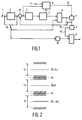
- FIG. 1 is a block diagram of the preferred embodiment of a device for restoring the DC component in an apparatus according to the invention.
- FIG. 2 illustrates the levels which are taken into account for decision and recoding in the case of a duobinary type signal, and of a threshold decoder.
- an amplified signal for example of the D2-MAC-Packet type, which first presents a period of digital data coded in duobinary whose duration is 10 "s, then a reference level of the average gray level which lasts only 0.75 ”s, followed by an analog signal period representing the chrominance information and an analog signal period representing the luminance information which terminates the line.
- the amplified signal available at 1 is brought first of all to a conventional DC voltage alignment device 2 based on the line bearings.
- the device then includes a decoder for digital data 3, then a coding member 4 for this data of the type used to create the received signal.
- the digital data decoder 3 can conventionally take the form of a low-pass filter with a cutoff frequency of 5 MHz followed by a threshold decoder or possibly a Viterbi decoder.
- An associated circuit 5 makes it possible to measure the validity of the reconstructed digital signal based on the signal present at the input of the decoder 3.
- the reconstructed coded digital signal is compared in the estimation circuit 6 with the available signal, the latter being taken either at the input 1 or at the output of the conventional DC voltage alignment system 2, this choice being symbolized in the figure by an inverter 18 which is not required to exist physically, a final choice of connection being able to be done by construction. From this comparison, the estimation circuit 6 forms a correction signal.
- the estimation circuit 6 is a circuit which subtracts the received signal and the reconstructed signal from each other.
- the estimation circuit 6 is followed by a filtering circuit 7.
- circuit 7 has information extracted from the duobinary burst and supplied by circuit 6, which allows, when validated, to reconstruct the low frequency component.
- This circuit 7, which takes, in a preferred embodiment, the form of a simple averager, provides a value-result per line.
- the correction signal is subtracted from the signal received at the input of the decoder 3, in a subtraction circuit 19. Depending on the position of the inverter 15, the signal thus subtracted is either the signal available at the output of the estimation circuit 6, or that available at the output of the filtering circuit 7.
- the inverter 15 may not exist in the case where a final connection is chosen during construction.
- the value-result from the filtering circuit 7 is then processed by a circuit 8 in order to refine its value by weighting it by those obtained for the preceding lines.
- This circuit which is a filter can either be of the recursive type and deliver information synchronous with the current line, or deliver information delayed by the duration of an integer number of lines.
- the correction signal is subtracted by the subtractor circuit 9, over the entire duration of a line, from the available signal, either at input 1, or possibly at output from the conventional DC voltage alignment system. 2, this signal possibly being delayed (depending on the delay of the line filter) in a circuit 10 in order to ensure the synchronization of the two signals.
- FIG. 2 in which the references 14 indicate decision thresholds and the references 13 indicate three ranges of the same width, said width defining a reliability threshold, illustrates the reconstruction of the duobinary train in the case where the element 3 is a decoder with threshold.
- This reconstruction is summarized by the following logical operations: if
- the control circuit 5 provides an estimate of the reliability of the reconstruction of the duobinary signal in the form of a validation signal 12 intended for the filtering module 7. It does this in the following manner: the reconstructed signal is compared to the duobinary signal present at the input of the decoder, and a voltage applied at 11 defines a reliability threshold which represents the maximum authorized difference between the two signals beyond which the reconstructed sample will no longer be taken into account in the calculation of the component low frequency. For example in the case of a decoding / recoding in D2-MAC-packet, which relates to one hundred and five bits per line, the decision of taking into account or not is taken for each of these one hundred and five bits.
- the device is provided with a validation circuit which, from the measurement of the difference between the received signal and the reconstructed signal, controls the taking into account of the correction signal.
- the circuit 8 making it possible to weight the information coming from the filter 7 by the values obtained on the preceding lines takes the form of a non-recursive filter called "Finite Impulse Response".
- the advantage of this filter is to have a response whose delay with respect to the input data is fixed for a given filter length and can thus be compensated to ensure perfect synchronization.
- a simple and advantageous embodiment is constituted by an averager which preferably acts on an odd number of data.
- the delay generated by the averager is equal to its half-length, and is therefore equal to (N-1) / 2 line periods if the filter acts on N data.
- the circuit 10 delays by this value the signal available at the input 1 or possibly at the output of the conventional DC voltage alignment system 2.
Description
La présente invention concerne un appareil destiné à recevoir un signal véhiculant des informations de luminance et de chrominance analogiques associées à des périodes de signal numérique codé, muni d'un dispositif de restitution de la composante continue et d'un circuit décodeur pour décoder le signal numérique reçu. Un tel signal est notamment un signal de type MAC, qui comporte des informations analogiques de luminance et de chrominance et des informations numériques codées par paquets ainsi que des paliers de tension analogique de référence de niveau de gris moyen.The present invention relates to an apparatus intended to receive a signal conveying analog luminance and chrominance information associated with periods of coded digital signal, provided with a device for restoring the DC component and a decoder circuit for decoding the signal. digital received. Such a signal is in particular a MAC type signal, which comprises analog luminance and chrominance information and digital information coded in packets as well as analog voltage reference steps of medium gray level.
Un tel appareil est par exemple un téléviseur équipé pour la réception d'un signal en D2-MAC/paquet, ou bien un "tuner satellite" ou même n'importe quel appareil muni d'un organe effectuant un traitement du signal dans un système de transmission.Such a device is for example a television equipped for the reception of a signal in D2-MAC / packet, or else a "satellite tuner" or even any device provided with a body performing a signal processing in a system of transmission.
Un tel appareil est connu par exemple de la demande de brevet FR-A-2 610 773. Selon ce document, un téléviseur est muni de moyens pour rétablir la composante continue, dans différentes étapes successives et exclusives l'une de l'autre, d'abord à partir des niveaux de crête mesurés sur la totalité du signal, puis à partir des niveaux de crête mesurés uniquement sur la partie du signal qui est numérique, et enfin à partir des paliers de tension de référence du signal.Such an apparatus is known for example from patent application FR-A-2 610 773. According to this document, a television set is provided with means for restoring the continuous component, in different successive and mutually exclusive stages, first from the peak levels measured over the entire signal, then from the peak levels measured only over the part of the signal that is digital, and finally from the reference voltage stages of the signal.
Le problème posé vient du fait que la composante dite "continue", qui comprend aussi une composante basse fréquence, est affectée par les perturbations inhérentes à tout système de transmission, qu'elles soient ou non corrélées avec le signal de télévision. Ces perturbations constituent un signal parasite comprenant deux composantes, le bruit à fréquence basse devant la fréquence ligne (cassure basse fréquence, dispersion d'énergie, résidu de 50 Hz, etc...), et le bruit de modulation dont la répartition spectrale de puissance dépend du type de transmission.The problem arises from the fact that the so-called "continuous" component, which also includes a low frequency component, is affected by the disturbances inherent in any transmission system, whether or not they are correlated with the television signal. These disturbances constitute a parasitic signal comprising two components, the low frequency noise in front of the line frequency (low frequency break, energy dispersion, 50 Hz residue, etc.), and the noise of modulation whose spectral power distribution depends on the type of transmission.
Dans le téléviseur décrit par le document ci-dessus, lorsqu'on utilise les niveaux de crête mesurés sur la partie numérique du signal, ces niveaux sont susceptibles de varier avec le contenu numérique du signal, et la restitution de la composante continue n'est pas précise, et lorsqu'on utilise le palier de référence pour extraire cette composante, on se heurte aux limites théoriques de restitution d'un signal dans du bruit. En effet, la trop faible durée du palier ne permet pas une intégration suffisante sur une ligne. Des filtres simples ont été proposés qui intégrent les informations de plusieurs lignes. Basés sur le principe d'un filtre récursif du premier ordre, ils possèdent l'avantage de réduire le bruit dans le cas de types de transmission défavorables, mais ils conduisent à une erreur de mesure de la composante basse fréquence. Les essais entrepris dans le cas d'une transmission d'un signal de télévision selon la norme D2-MAC Paquets montrent la difficulté de réaliser un compromis entre bruit et résidus basse fréquence, compromis devant être adapté à chaque cas particulier que constitue chaque type de modulation.In the television described by the document above, when the peak levels measured on the digital part of the signal are used, these levels are liable to vary with the digital content of the signal, and the reproduction of the continuous component is not not precise, and when we use the reference level to extract this component, we come up against the theoretical limits of restitution of a signal in noise. Indeed, the too short duration of the bearing does not allow sufficient integration on a line. Simple filters have been proposed which integrate the information of several lines. Based on the principle of a first-order recursive filter, they have the advantage of reducing noise in the case of unfavorable transmission types, but they lead to a measurement error of the low frequency component. The tests undertaken in the case of a transmission of a television signal according to the D2-MAC Packet standard show the difficulty of achieving a compromise between noise and low frequency residues, compromise having to be adapted to each particular case that constitutes each type of modulation.
L'invention fournit un appareil dans lequel ces problèmes sont résolus. A cet effet, le dispositif de restitution de la composante continue comprend un organe de codage réalisant à partir du signal numérique décodé un codage identique à celui utilisé pour la création du signal reçu, un circuit d'estimation de la composante continue calculant ladite estimation à partir des différences entre le signal codé reçu et le signal codé reconstruit par le susdit organe de codage, cette estimation constituant un signal de correction de composante continue, et un circuit soustracteur pour retrancher au signal reçu ledit signal de correction, sur toute la durée d'une ligne.The invention provides an apparatus in which these problems are solved. To this end, the device for restoring the DC component comprises a coding member carrying out from the decoded digital signal a coding identical to that used for the creation of the received signal, a circuit for estimating the DC component calculating said estimate at starting from the differences between the received coded signal and the coded signal reconstructed by the above coding member, this estimation constituting a DC component correction signal, and a subtractor circuit for subtracting from the received signal said correction signal, over the entire duration d 'a line.
Il comporte aussi avantageusement, en sortie du circuit d'estimation, un circuit de filtrage, qui est avantageusement un simple moyenneur. Ceci a pour avantage de diminuer l'incidence du bruit sur la détermination de la composante continue.It also advantageously comprises, at the output of the estimation circuit, a filtering circuit, which is advantageously a simple averager. This has the advantage of reducing the incidence of noise on the determination of the component keep on going.
L'appareil comporte avantageusement en aval du circuit d'estimation de la composante continue un filtre utilisant les signaux de correction de plusieurs périodes de balayage de lignes à la fois pour affiner le signal de correction, avant sa soustraction au signal reçu dans le circuit soustracteur, ce filtre étant du type à réponse impulsionnelle finie, par exemple un moyenneur, et un circuit de retardement du signal reçu placé en aval du circuit soustracteur, pour compenser le retard dû au filtre.The device advantageously comprises downstream of the DC component estimation circuit a filter using the correction signals from several line scanning periods at the same time to refine the correction signal, before its subtraction from the signal received in the subtractor circuit. , this filter being of the finite impulse response type, for example an averager, and a delay circuit of the received signal placed downstream of the subtractor circuit, to compensate for the delay due to the filter.
L'invention est donc basée sur le principe d'extraire des informations supplémentaires sur la composante basse fréquence du signal en exploitant efficacement la période numérique, et d'autre part d'intégrer ces informations sur plusieurs lignes à l'aide d'un filtre approprié préservant la composante basse fréquence.The invention is therefore based on the principle of extracting additional information on the low frequency component of the signal by efficiently exploiting the digital period, and on the other hand integrating this information over several lines using a filter. suitable preserving the low frequency component.
L'appareil est en outre avantageusement muni, à l'entrée du décodeur, d'un circuit de soustraction dans lequel le signal de correction est soustrait au signal reçu. Cela a pour effet d'augmenter la fiabilité du décodage.The apparatus is also advantageously provided, at the input of the decoder, with a subtraction circuit in which the correction signal is subtracted from the received signal. This has the effect of increasing the reliability of the decoding.
Une autre caractéristique importante de l'invention est basée sur la remarque que la présence de l'organe de codage permet une estimation de la fiabilité du signal reçu. L'appareil est donc avantageusement muni d'un circuit de validation qui, à partir de la mesure de l'écart entre le signal reçu et le signal reconstruit, commande la prise en compte du signal de correction.Another important characteristic of the invention is based on the remark that the presence of the coding member allows an estimation of the reliability of the received signal. The device is therefore advantageously provided with a validation circuit which, from the measurement of the difference between the received signal and the reconstructed signal, controls the taking into account of the correction signal.
La figure 1 est un schéma synoptique du mode de réalisation préféré d'un dispositif de restitution de la composante continue dans un appareil selon l'invention.FIG. 1 is a block diagram of the preferred embodiment of a device for restoring the DC component in an apparatus according to the invention.
La figure 2 illustre des niveaux qui sont pris en compte pour décision et recodage dans le cas d'un signal de type duobinaire, et d'un décodeur à seuil.FIG. 2 illustrates the levels which are taken into account for decision and recoding in the case of a duobinary type signal, and of a threshold decoder.
On dispose d'un signal amplifié, par exemple de type D2-MAC-Paquet, qui présente d'abord une période de données numériques codées en duobinaire dont la durée est de 10»s, puis un palier de référence du niveau de gris moyen qui ne dure que 0,75»s, suivi d'une période de signal analogique représentant les informations de chrominance et d'une période de signal analogique représentant les informations de luminance qui terminent la ligne.There is an amplified signal, for example of the D2-MAC-Packet type, which first presents a period of digital data coded in duobinary whose duration is 10 "s, then a reference level of the average gray level which lasts only 0.75 ”s, followed by an analog signal period representing the chrominance information and an analog signal period representing the luminance information which terminates the line.
Sur la figure 1, le signal amplifié disponible en 1 est amené en premier lieu à un dispositif classique d'alignement de la tension continue 2 basé sur les paliers de ligne. Le dispositif comporte ensuite un décodeur des données numériques 3, puis un organe de codage 4 de ces données du type de ceux utilisés pour créer le signal reçu. Le décodeur de données numérique 3 peut prendre classiquement la forme d'un filtre passe-bas de fréquence de coupure 5 MHz suivi d'un décodeur à seuil ou éventuellement un décodeur de Viterbi.In FIG. 1, the amplified signal available at 1 is brought first of all to a conventional DC
Un circuit associé 5 permet de mesurer la validité du signal numérique reconstruit en se basant sur le signal présent à l'entrée du décodeur 3. Le signal numérique codé reconstruit est comparé dans le circuit d'estimation 6 au signal disponible, celui ci étant prélevé soit à l'entrée 1, soit en sortie du système classique d'alignement de la tension continue 2, ce choix étant symbolisé sur la figure par un inverseur 18 qui n'est pas obligé d'exister physiquement, un choix définitif de branchement pouvant être fait par construction. A partir de cette comparaison, le circuit d'estimation 6 forme un signal de correction. Dans sa forme la plus simple le circuit d'estimation 6 est un circuit qui soustrait l'un de l'autre le signal reçu et le signal reconstruit . Il peut aussi, dans une version plus sophistiquée, mais non indispensable, prendre la forme d'un circuit récursif qui corrige un signal de correction précédent en lui ajoutant un signal calculé à partir des différences entre le signal reçu et le signal reconstruit (c'est-à-dire non seulement la différence au sens arithmétique mais aussi d'autres paramètres représentant une non similitude) pondérées par un coefficient fixe ou variable qui peut dépendre des caractéristiques du canal de transmission.An
Le circuit d'estimation 6 est suivi par un circuit de filtrage 7. En plus des informations présentes sur le palier de référence ordinaire (dont on dispose toujours, les signaux de ce palier étant traités par le circuit 6 comme faisant partie de la salve duobinaire), le circuit 7 dispose des informations extraites de la salve duobinaire et fournies par le circuit 6, qui permettent, lorsqu'elles sont validées, de reconstituer la composante basse fréquence. Ce circuit 7, qui prend, dans un mode de réalisation préférentiel, la forme d'un simple moyenneur, fournit une valeur-résultat par ligne. Le signal de correction est soustrait du signal reçu à l'entrée du décodeur 3, dans un circuit de soustraction 19. Selon la position de l'inverseur 15, le signal ainsi soustrait est soit le signal disponible à la sortie du circuit d'estimation 6, soit celui disponible à la sortie du circuit de filtrage 7. Comme dans le cas de l'inverseur 18, l'inverseur 15 peut ne pas exister au cas où un branchement définitif est choisi à la construction. La valeur-résultat issue du circuit de filtrage 7 est ensuite traitée par un circuit 8 afin d'affiner sa valeur en la pondérant par celles obtenues pour les lignes précédentes. Ce circuit qui est un filtre peut soit être du type récursif et délivrer une information synchrone avec la ligne courante, soit délivrer une information retardée de la durée d'un nombre entier de lignes. En dernier lieu, le signal de correction est soustrait par le circuit soustracteur 9, sur toute la durée d'une ligne, au signal disponible, soit à l'entrée 1, soit éventuellement en sortie du système classique d'alignement de la tension continue 2, ce signal étant éventuellement retardé (selon le retard du filtre de lignes) dans un circuit 10 afin d'assurer la synchronisation des deux signaux.The
La figure 2 dans laquelle les références 14 indiquent des seuils de décision et les références 13 indiquent trois plages de même largeur, ladite largeur définissant un seuil de fiabilité, illustre la reconstruction du train duobinaire dans le cas où l'élément 3 est un décodeur à seuil.FIG. 2 in which the
Cette reconstruction est résumée par les opérations logiques suivantes :
si |ck-Cc| ≦ seuil de décision(14), alors ĉk=0
si ck-Cc < seuil de décision négatif(14), alors ĉk=-0,4
si ck-Cc > seuil de décision positif(14), alors Ĉk=+0,4
où ck représente la valeur (valeurs numériques en volts) de l'échantillon duobinaire reçu ĉk la valeur de l'échantillon duobinaire reconstruit, et Cc la valeur de la composante continue soustraite à l'entrée du décodeur 3.This reconstruction is summarized by the following logical operations:
if | c k -C c | ≦ decision threshold (14), then ĉ k = 0
if c k -C c <negative decision threshold (14), then ĉ k = -0.4
if c k -C c > positive decision threshold (14), then Ĉ k = + 0.4
where c k represents the value (numerical values in volts) of the duobinary sample received ĉ k the value of the reconstructed duobinary sample, and C c the value of the continuous component subtracted from the input of the
Le circuit de contrôle 5 fournit une estimation de fiabilité de la reconstruction du signal duobinaire sous la forme d'un signal de validation 12 destiné au module de filtrage 7. Il agit pour cela de la manière suivante : le signal reconstruit est comparé au signal duobinaire présent à l'entrée du décodeur, et une tension appliquée en 11 définit un seuil de fiabilité qui représente la différence maximale autorisée entre les deux signaux au-delà de laquelle l'échantillon reconstruit ne sera plus pris en compte dans le calcul de la composante basse fréquence. Par exemple dans le cas d'un décodage/recodage en D2-MAC-paquet, qui porte sur cent cinq bits par ligne, la décision de prise en compte ou non est prise pour chacun de ces cent cinq bits.The
La fonction remplie par ce circuit 5, qui est très simple, est résumée par l'opération logique suivante :
si |ck-Cc-ĉk|< seuil de fiabilité, alors validation.The function fulfilled by this
if | c k -C c -ĉ k | <reliability threshold, then validation.
Ainsi le dispositif est muni d'un circuit de validation qui, à partir de la mesure de l'écart entre le signal reçu et le signal reconstruit, commande la prise en compte du signal de correction.Thus the device is provided with a validation circuit which, from the measurement of the difference between the received signal and the reconstructed signal, controls the taking into account of the correction signal.
Dans un mode de réalisation préférentiel, le circuit 8 permettant de pondérer l'information issue du filtre 7 par les valeurs obtenues sur les lignes précédentes prend la forme d'un filtre non récursif dit à "Réponse Impulsionnelle Finie". L'avantage de ce filtre est d'avoir une réponse dont le retard par rapport aux données d'entrée est fixé pour une longueur de filtre donnée et pourra ainsi être compensé afin d'assurer une synchronisation parfaite.In a preferred embodiment, the
Une réalisation simple et avantageuse est constituée par un moyenneur qui agit de préférence sur un nombre impair de données. Le retard engendré par le moyenneur est égal à sa demi-longueur, et vaut donc (N-1)/2 périodes de ligne si le filtre agit sur N données. Dans ce cas, le circuit 10 retarde de cette valeur le signal disponible à l'entrée 1 ou éventuellement en sortie du système classique d'alignement de la tension continue 2.A simple and advantageous embodiment is constituted by an averager which preferably acts on an odd number of data. The delay generated by the averager is equal to its half-length, and is therefore equal to (N-1) / 2 line periods if the filter acts on N data. In this case, the
Claims (9)
- An apparatus for receiving a signal conveying analog luminance and chrominance information associated with coded digital signal periods, comprising a d.c. restoration circuit and a decoder circuit (3) for decoding the received digital signal, characterised in that the d.c. restoration circuit comprises a coding device (4) which on the basis of the decoded digital signal performs a coding operation similar that used to generate the received signal, a d.c. component estimation circuit (6) which calculates an estimate from the differences between the coded signal received (1) and the coded signal reconstructed by said coding device, which estimate constitutes a d.c. component correction signal, and a subtracter circuit (9) for subtracting said correction signal from the received signal throughout the duration of one line.
- An apparatus as claimed in Claim 1, characterised in that it includes a filter circuit (7) at the output of the estimation circuit.
- An apparatus as claimed in Claim 2, characterised in that the filter circuit (7) is a simple averager.
- An apparatus as claimed in Claim 1, characterised in that downstream the d.c. component estimation circuit (6) it includes a filter (8) using the correction signals of several line scanning periods at a time to improve the correction signal, before the subtracter circuit (9) subtracts this correction signal from the received signal, said filter being of the finite impulse response type, for example an averager, and a delay circuit (10) arranged downstream the subtracter circuit (9), for delaying the received signal to compensate for the delay caused by the filter (8).
- An apparatus as claimed in any one of the preceding Claims, characterized in that at the input of the decoder (3) it includes a subtracter circuit (19) which subtracts the correction signal from the received signal.
- An apparatus as claimed in any one of the preceding Claims, wherein the decoder (3) is of the type having a threshold, characterised in that the coding device (4) is a logic circuit performing the following logic operations:
if |ck-Cc|≦ decision threshold, ĉk = 0,
if ck-Cc < negative decision threshold (14), ĉk assumes a negative standard value
if ck-Cc > positive decision threshold, ĉk assumes a positive standard value, where ck represents the value of the received duobinary sample, ĉk represents the value of the reconstructed duobinary sample, and Cc represents the value of the correction signal. - An apparatus as claimed in any one of the Claims 1 to 6, characterised in that it includes a validation circuit (5) which, on the basis of the measurement of the deviation between the received signal and the reconstructed signal, determines whether the correction signal is to be taken into account.
- An apparatus as claimed in Claim 7, characterised in that the validation circuit (5) decides that the correction signal is to be taken into account if |ck-Cc-ĉk| is smaller than a given reliability threshold, ck representing the value of the received duobinary sample, ĉk representing the value of the reconstructed binary sample, and Cc representing the value of the correction signal.
- An apparatus as claimed in any one of the preceding Claims, characterised in that upstream the decoder it further includes a d.c. clamping device (2) based on analog voltage porches contained in the received signal.
Applications Claiming Priority (4)
| Application Number | Priority Date | Filing Date | Title |
|---|---|---|---|
| FR8814685 | 1988-11-10 | ||
| FR8814685A FR2638925B1 (en) | 1988-11-10 | 1988-11-10 | APPARATUS WITH IMPROVED CONTINUOUS COMPONENT RETURN DEVICE |
| FR8907097 | 1989-05-30 | ||
| FR8907097A FR2647996B3 (en) | 1989-05-30 | 1989-05-30 | APPARATUS WITH IMPROVED CONTINUOUS COMPONENT RETURN DEVICE |
Publications (2)
| Publication Number | Publication Date |
|---|---|
| EP0368417A1 EP0368417A1 (en) | 1990-05-16 |
| EP0368417B1 true EP0368417B1 (en) | 1995-02-01 |
Family
ID=26226981
Family Applications (1)
| Application Number | Title | Priority Date | Filing Date |
|---|---|---|---|
| EP89202825A Expired - Lifetime EP0368417B1 (en) | 1988-11-10 | 1989-11-08 | Apparatus comprising an improved device for clamp-error compensation |
Country Status (7)
| Country | Link |
|---|---|
| US (1) | US5036388A (en) |
| EP (1) | EP0368417B1 (en) |
| JP (1) | JPH02214269A (en) |
| KR (1) | KR900008880A (en) |
| DE (1) | DE68920953T2 (en) |
| ES (1) | ES2070171T3 (en) |
| HK (1) | HK66896A (en) |
Families Citing this family (3)
| Publication number | Priority date | Publication date | Assignee | Title |
|---|---|---|---|---|
| FR2675331A1 (en) * | 1991-04-12 | 1992-10-16 | Philips Electro Grand Public | APPARATUS PROVIDED WITH AN IMPROVED DEVICE FOR REINSTALLING THE CONTINUOUS COMPONENT. |
| KR20000068950A (en) * | 1997-09-12 | 2000-11-25 | 요트.게.아. 롤페즈 | Transmission system with improved reconstruction of missing parts |
| US20030219085A1 (en) * | 2001-12-18 | 2003-11-27 | Endres Thomas J. | Self-initializing decision feedback equalizer with automatic gain control |
Family Cites Families (4)
| Publication number | Priority date | Publication date | Assignee | Title |
|---|---|---|---|---|
| JPS57208770A (en) * | 1981-06-19 | 1982-12-21 | Hitachi Ltd | Dc level automatic compensating circuit for analog signal repetitively including reference level signal |
| FR2565448B1 (en) * | 1984-06-04 | 1986-10-10 | France Etat | SYNCHRONIZATION EXTRACTION METHOD AND DEVICE FOR TIME-MULTIPLEXED BROADCASTING SYSTEM OF DIGITAL AND ANALOG SIGNALS |
| US4713694A (en) * | 1985-09-09 | 1987-12-15 | Hughes Aircraft Company | Noninvasive DC restoration to upgrade AC coupled systems |
| FR2610773B1 (en) * | 1987-02-06 | 1989-05-26 | Radiotechnique Ind & Comm | SYNCHRONIZATION SYSTEM ON A SEMI-DIGITAL SIGNAL |
-
1989
- 1989-11-03 US US07/431,499 patent/US5036388A/en not_active Expired - Fee Related
- 1989-11-08 EP EP89202825A patent/EP0368417B1/en not_active Expired - Lifetime
- 1989-11-08 ES ES89202825T patent/ES2070171T3/en not_active Expired - Lifetime
- 1989-11-08 JP JP1288936A patent/JPH02214269A/en active Pending
- 1989-11-08 DE DE68920953T patent/DE68920953T2/en not_active Expired - Fee Related
- 1989-11-10 KR KR1019890016253A patent/KR900008880A/en not_active Application Discontinuation
-
1996
- 1996-04-18 HK HK66896A patent/HK66896A/en not_active IP Right Cessation
Also Published As
| Publication number | Publication date |
|---|---|
| JPH02214269A (en) | 1990-08-27 |
| ES2070171T3 (en) | 1995-06-01 |
| EP0368417A1 (en) | 1990-05-16 |
| HK66896A (en) | 1996-04-26 |
| DE68920953T2 (en) | 1995-08-31 |
| US5036388A (en) | 1991-07-30 |
| DE68920953D1 (en) | 1995-03-16 |
| KR900008880A (en) | 1990-06-04 |
Similar Documents
| Publication | Publication Date | Title |
|---|---|---|
| EP0246701B1 (en) | Dpcm coder and associated decoder | |
| EP0022723A1 (en) | Method and apparatus for digital data extraction in presence of noise and distorsion | |
| FR2596221A1 (en) | ADAPTIVE MEDIAN FILTER SYSTEM | |
| FR2571566A1 (en) | DIGITAL DATA RECEIVING DEVICE HAVING AN ADAPTIVE RHYTHM RECOVERY DEVICE | |
| FR2478909A1 (en) | ||
| EP0418952B1 (en) | Coding device for bidimensional informations, and decoding device therefor | |
| EP0869476B1 (en) | Comfort noise generation device | |
| EP0368417B1 (en) | Apparatus comprising an improved device for clamp-error compensation | |
| WO1989010040A1 (en) | High definition television image coding device and transmission system | |
| EP0078195B1 (en) | Process and system for the differential coding and decoding of data, with limitation of the propagation of transmission errors | |
| FR2647996A3 (en) | Apparatus provided with an enhanced device for continuous component restoration | |
| EP0030194B1 (en) | Predictive stage for a dataflow compression system | |
| EP0063990A1 (en) | Method for image transmission with reduced data rate; transmission system for executing this method | |
| FR2638925A1 (en) | Apparatus provided with an improved device for restoring the DC component | |
| EP0348322B1 (en) | Method for the restoration of the continuous component of a dmac type signal, device therefor and use thereof | |
| EP0528738B1 (en) | Method and circuit for adapting the coefficients in the equalizer of a modem | |
| EP0905946B1 (en) | Control of the sampling of biphase signals | |
| FR2690032A1 (en) | Television alignment method and device for its implementation. | |
| EP0160595B1 (en) | Circuit for coding and decoding a video signal coded by shifting the image signal relative to the synchronising signal | |
| FR2675331A1 (en) | APPARATUS PROVIDED WITH AN IMPROVED DEVICE FOR REINSTALLING THE CONTINUOUS COMPONENT. | |
| FR2595896A1 (en) | DEVICE FOR THE DIGITAL DECODING OF TELEVISION SIGNALS WITH ADAPTIVE MEANS FOR SEPARATING LUMINANCE AND CHROMINANCE | |
| CA2019774C (en) | Device for detecting in a binary signal a pointer consisting of a continuous sequence of binary elements having the same value | |
| EP0451754B1 (en) | Digital autoadaptive equalizer | |
| EP0295974B1 (en) | Method and device for decoding duobinary signals transmitted in bursts | |
| FR2823338A1 (en) | Digital MPEG post processing having frequency transformation step providing transformed coefficient assembly with original base/high frequency coefficients extracted/correction step carried out/combined transformed coefficients produced. |
Legal Events
| Date | Code | Title | Description |
|---|---|---|---|
| PUAI | Public reference made under article 153(3) epc to a published international application that has entered the european phase |
Free format text: ORIGINAL CODE: 0009012 |
|
| AK | Designated contracting states |
Kind code of ref document: A1 Designated state(s): DE ES FR GB IT |
|
| 17P | Request for examination filed |
Effective date: 19901114 |
|
| 17Q | First examination report despatched |
Effective date: 19930625 |
|
| GRAA | (expected) grant |
Free format text: ORIGINAL CODE: 0009210 |
|
| AK | Designated contracting states |
Kind code of ref document: B1 Designated state(s): DE ES FR GB IT |
|
| REF | Corresponds to: |
Ref document number: 68920953 Country of ref document: DE Date of ref document: 19950316 |
|
| ITF | It: translation for a ep patent filed |
Owner name: ING. C. GREGORJ S.P.A. |
|
| GBT | Gb: translation of ep patent filed (gb section 77(6)(a)/1977) |
Effective date: 19950420 |
|
| REG | Reference to a national code |
Ref country code: ES Ref legal event code: FG2A Ref document number: 2070171 Country of ref document: ES Kind code of ref document: T3 |
|
| PLBE | No opposition filed within time limit |
Free format text: ORIGINAL CODE: 0009261 |
|
| STAA | Information on the status of an ep patent application or granted ep patent |
Free format text: STATUS: NO OPPOSITION FILED WITHIN TIME LIMIT |
|
| 26N | No opposition filed | ||
| REG | Reference to a national code |
Ref country code: FR Ref legal event code: CJ Ref country code: FR Ref legal event code: CD |
|
| PGFP | Annual fee paid to national office [announced via postgrant information from national office to epo] |
Ref country code: GB Payment date: 19961101 Year of fee payment: 8 |
|
| PGFP | Annual fee paid to national office [announced via postgrant information from national office to epo] |
Ref country code: ES Payment date: 19961107 Year of fee payment: 8 |
|
| PGFP | Annual fee paid to national office [announced via postgrant information from national office to epo] |
Ref country code: FR Payment date: 19961119 Year of fee payment: 8 |
|
| PGFP | Annual fee paid to national office [announced via postgrant information from national office to epo] |
Ref country code: DE Payment date: 19970127 Year of fee payment: 8 |
|
| PG25 | Lapsed in a contracting state [announced via postgrant information from national office to epo] |
Ref country code: GB Free format text: LAPSE BECAUSE OF NON-PAYMENT OF DUE FEES Effective date: 19971108 |
|
| PG25 | Lapsed in a contracting state [announced via postgrant information from national office to epo] |
Ref country code: ES Free format text: LAPSE BECAUSE OF EXPIRATION OF PROTECTION Effective date: 19971110 |
|
| PG25 | Lapsed in a contracting state [announced via postgrant information from national office to epo] |
Ref country code: FR Free format text: THE PATENT HAS BEEN ANNULLED BY A DECISION OF A NATIONAL AUTHORITY Effective date: 19971130 |
|
| GBPC | Gb: european patent ceased through non-payment of renewal fee |
Effective date: 19971108 |
|
| PG25 | Lapsed in a contracting state [announced via postgrant information from national office to epo] |
Ref country code: DE Free format text: LAPSE BECAUSE OF NON-PAYMENT OF DUE FEES Effective date: 19980801 |
|
| REG | Reference to a national code |
Ref country code: FR Ref legal event code: ST |
|
| REG | Reference to a national code |
Ref country code: ES Ref legal event code: FD2A Effective date: 20010301 |
|
| PG25 | Lapsed in a contracting state [announced via postgrant information from national office to epo] |
Ref country code: IT Free format text: LAPSE BECAUSE OF NON-PAYMENT OF DUE FEES;WARNING: LAPSES OF ITALIAN PATENTS WITH EFFECTIVE DATE BEFORE 2007 MAY HAVE OCCURRED AT ANY TIME BEFORE 2007. THE CORRECT EFFECTIVE DATE MAY BE DIFFERENT FROM THE ONE RECORDED. Effective date: 20051108 |