EP0368037A1 - Process for controlling the distribution of the evaporation rate of an electron beam - Google Patents
Process for controlling the distribution of the evaporation rate of an electron beam Download PDFInfo
- Publication number
- EP0368037A1 EP0368037A1 EP89119229A EP89119229A EP0368037A1 EP 0368037 A1 EP0368037 A1 EP 0368037A1 EP 89119229 A EP89119229 A EP 89119229A EP 89119229 A EP89119229 A EP 89119229A EP 0368037 A1 EP0368037 A1 EP 0368037A1
- Authority
- EP
- European Patent Office
- Prior art keywords
- control
- correction
- variable
- grid
- memory
- Prior art date
- Legal status (The legal status is an assumption and is not a legal conclusion. Google has not performed a legal analysis and makes no representation as to the accuracy of the status listed.)
- Granted
Links
Images


Classifications
-
- C—CHEMISTRY; METALLURGY
- C23—COATING METALLIC MATERIAL; COATING MATERIAL WITH METALLIC MATERIAL; CHEMICAL SURFACE TREATMENT; DIFFUSION TREATMENT OF METALLIC MATERIAL; COATING BY VACUUM EVAPORATION, BY SPUTTERING, BY ION IMPLANTATION OR BY CHEMICAL VAPOUR DEPOSITION, IN GENERAL; INHIBITING CORROSION OF METALLIC MATERIAL OR INCRUSTATION IN GENERAL
- C23C—COATING METALLIC MATERIAL; COATING MATERIAL WITH METALLIC MATERIAL; SURFACE TREATMENT OF METALLIC MATERIAL BY DIFFUSION INTO THE SURFACE, BY CHEMICAL CONVERSION OR SUBSTITUTION; COATING BY VACUUM EVAPORATION, BY SPUTTERING, BY ION IMPLANTATION OR BY CHEMICAL VAPOUR DEPOSITION, IN GENERAL
- C23C14/00—Coating by vacuum evaporation, by sputtering or by ion implantation of the coating forming material
- C23C14/22—Coating by vacuum evaporation, by sputtering or by ion implantation of the coating forming material characterised by the process of coating
- C23C14/24—Vacuum evaporation
- C23C14/28—Vacuum evaporation by wave energy or particle radiation
- C23C14/30—Vacuum evaporation by wave energy or particle radiation by electron bombardment
-
- C—CHEMISTRY; METALLURGY
- C23—COATING METALLIC MATERIAL; COATING MATERIAL WITH METALLIC MATERIAL; CHEMICAL SURFACE TREATMENT; DIFFUSION TREATMENT OF METALLIC MATERIAL; COATING BY VACUUM EVAPORATION, BY SPUTTERING, BY ION IMPLANTATION OR BY CHEMICAL VAPOUR DEPOSITION, IN GENERAL; INHIBITING CORROSION OF METALLIC MATERIAL OR INCRUSTATION IN GENERAL
- C23C—COATING METALLIC MATERIAL; COATING MATERIAL WITH METALLIC MATERIAL; SURFACE TREATMENT OF METALLIC MATERIAL BY DIFFUSION INTO THE SURFACE, BY CHEMICAL CONVERSION OR SUBSTITUTION; COATING BY VACUUM EVAPORATION, BY SPUTTERING, BY ION IMPLANTATION OR BY CHEMICAL VAPOUR DEPOSITION, IN GENERAL
- C23C14/00—Coating by vacuum evaporation, by sputtering or by ion implantation of the coating forming material
- C23C14/22—Coating by vacuum evaporation, by sputtering or by ion implantation of the coating forming material characterised by the process of coating
- C23C14/54—Controlling or regulating the coating process
-
- H—ELECTRICITY
- H01—ELECTRIC ELEMENTS
- H01J—ELECTRIC DISCHARGE TUBES OR DISCHARGE LAMPS
- H01J37/00—Discharge tubes with provision for introducing objects or material to be exposed to the discharge, e.g. for the purpose of examination or processing thereof
- H01J37/30—Electron-beam or ion-beam tubes for localised treatment of objects
- H01J37/302—Controlling tubes by external information, e.g. programme control
-
- H—ELECTRICITY
- H01—ELECTRIC ELEMENTS
- H01J—ELECTRIC DISCHARGE TUBES OR DISCHARGE LAMPS
- H01J37/00—Discharge tubes with provision for introducing objects or material to be exposed to the discharge, e.g. for the purpose of examination or processing thereof
- H01J37/30—Electron-beam or ion-beam tubes for localised treatment of objects
- H01J37/305—Electron-beam or ion-beam tubes for localised treatment of objects for casting, melting, evaporating or etching
Definitions
- the present invention relates to a method for controlling the time-averaged evaporation rate generated by means of at least one electron beam over a predefined evaporation surface, to a predefined evaporation rate distribution over the surface, in which a control variable grid for at least one operating parameter of the electron beam is assigned to the surface and with the electron beam, controlled with the control parameters of the grid, the surface being processed, and an electron beam control.
- EP-A-0 104 922 it is known to image a computer-stored pattern on the surface of an IC as part of a lithographic process using a low-power, fine electron beam.
- coarser pattern areas are distinguished from finer ones and the area of the beam is kept constant over the areas in accordance with the respective requirements, so that the beam area does not have to be changed in every beam position.
- an IC surface represents a small, flat, time-constant processing surface for the fine beam to be deflected only by small angles and the beam effect is clearly defined in the context of the lithographic process
- an evaporated surface forms a large, irregularly profiled, temporally primarily The processing surface for the powerful electron beam to be deflected by a relatively large angle, and the respective beam effect on the processing surface cannot be estimated from the outset.
- DE-OS 34 28 802 has now disclosed a method of the type mentioned initially, according to which a position grid for the electron beam is initially assigned to a given evaporation surface and the electron beam is guided in steps from one grid element to the other over the surface.
- Each element of the position grid which is triggered by the electron beam when processing the evaporation surface, is assigned its own control variable, thus the same number of control variables as are provided on the position grid position elements.
- the individual control variables assigned to the elements of the position grid thus jointly form a control variable grid for the electron beam that is assigned to the surface to be evaporated.
- the control variables are used to control operating parameters of the electron beam, such as its dwell time at a position determined by the position grid, its focusing there or its power.
- the exhaust steam system is retracted and these control variables are adjusted until a desired evaporation rate distribution over the surface is realized. It is necessary to achieve such a desired evaporation rate distribution in order to, for example, uniformly vaporization in a vacuum vaporization chamber of the system.
- control variable to be newly set must at least be queried and, if need be, set, queried in any case, even if it does so shows that there is no need to change the tax size when moving from one position to another.
- the aim of the present invention is to remedy the disadvantages mentioned, starting from a method of the type mentioned above.
- the storage effort for the correction quantities of the correction quantity grid is significantly reduced and the control process becomes faster, because as long as the beam position does not jump from one field of constant correction quantity to the correction quantity, the correction quantity can be kept constant without a query. Accordingly, it only has to be detected when the beam position exceeds the field boundary mentioned.
- the invention is based on the knowledge that it is not necessary to specify operating parameter control variables or correction variables for the electron beam, corresponding to a position grid distributed uniformly over the surface, separately for each position element or increment.
- the heat distribution over the surface to be evaporated can be represented by self-contained lines, actual isotherms, on which lines the same thermal conditions are present and therefore the same correction parameters have to be brought into effect.
- local changes in the jet evaporation effect caused by the beam deflection or changes in focus along the evaporated profile can be represented in a map-like manner by connecting beam positions in which the same changes occur.
- At least one correction size grid is thus created which, similar to a map or a relief, has fields assigned to partial areas of the evaporation surface, each corresponding to a plurality of beam positions and with constant correction values, which achieve the advantages mentioned.
- correction variable grids are provided with associated field divisions, for example one of the physical influences mentioned correcting.
- the control size grid which ultimately influences a jet operating parameter, such as and preferably its dwell time at a position and / or its focusing or power, is determined by linking the respective correction sizes assigned to a beam position, that is to say the entire control size grid over the area to be evaporated by linking of the intended correction size grid.
- correction variable grids can optionally be used to form the control variable grid if several correction variable grids are provided, as has just been explained.
- the electron beam can, as has been customary up to now, be guided independently of one another in a position grid from position element to position element, wherein, with a corresponding reduction in the size of the position elements, the beam guidance finally changes into a continuous beam guidance.
- An electron beam control for an evaporation system with a deflection control for the beam, which controls the beam position for processing an evaporation surface via the latter, and with a control unit for controlling beam operating parameters, is characterized by the wording of claim 8.
- the deflection control system emits position identification signals which identify beam positions still to be processed. For a given beam path, the deflection controller identifies the next beam position to be processed. If, however, in the sense of the aforementioned automatic search for an optimal beam guiding path, the principle of minimal control variable gradients is used, the beam position identified and identified by the deflection control does not also need that to be processed next, because for this, as will be specified further, it is first necessary to determine from the plurality or at least the neighboring beam positions still to be processed that which gives the minimum control variable gradient mentioned.
- Storage means are also provided for storing correction variables for beam operating parameters and assignment means which assign several beam positions to the same storage location of the storage means with the same correction variable, which, as explained in the procedure in the introduction, together for several beam positions, be it a predetermined beam path or an independently searched one Correction size fields of constant correction size are defined.
- the correction variables output now act as a control variable on at least one control input of the control unit for beam operating parameters, in particular for its beam dwell time and / or focusing and / or power etc.
- the deflection control finally leads the beam to a next position after the control variable has been found. This in turn corresponds to either a predefined position (in the case of beam guidance along a predefined path) or a predefined position.
- a selection unit which, starting from an actual position of the beam given by the identification signals and from this position assigned memory location of the correction variable memory and therefore from the current control variable, searches for a position for the beam whose assigned control variable dependent on the correction variable in the correction variable memory deviates minimally from the control variable which corresponds to the current position.
- the selection unit therefore searches for a next beam position, so that the necessary change in the control variable is minimal.
- the selection unit then emits a position control signal to the deflection control in order to steer the beam into the found position as the next position.
- the deflection control controls the beam in a predetermined position grid over the surface and the selection unit selects a position as the next position which is adjacent to the instantaneous position of the beam .
- a plurality of storage means are provided for correction quantities, the allocation means assigning a plurality of beam positions per storage location with the same contents to each storage means.
- the actual fields are defined in words in each storage medium, following the method according to the invention.
- Each of the correction variables from the storage means is directed to a link unit, the output of which acts on the control unit with at least one control variable.
- the linking unit is preferably an additive or multiplicative unit, wherein at most factors associated with storage means can be set for an additive linking on the linking unit.
- FIG. 1 shows a combined signal flow function block diagram of a first embodiment variant of a control according to the invention for executing the method according to the invention.
- a deflection control unit 1 comprises a position clock 1a and a position memory 1b.
- an evaporation surface 14 to be evaporated for example on a crucible 15
- the x, y values of these beam positions to be controlled are stored in the position memory 1b and their number, 1 to n, can be output at an output A 1.
- the position clock generator 1a cyclically activates the position memory 1b via its output c1, so that the latter outputs at its output A1 the respective x, y values to be controlled, which are supplied to the position controller 3a of the electron gun 3.
- a switching unit T 1 is initially opened.
- the position signal x, y then output at the output A 1 is fed to a field assignment memory 5.
- each of the n intended beam positions x, y are assigned field identifications A, B ..., a plurality of positions x, y jointly belonging to the same field identifications.
- the field assignment memory 5 thus comprises significantly fewer field identifications A, B ... than beam positions can be controlled by the deflection control unit 1.
- the respective field identification is output at its output A 4.
- the field identification which is now output at the output A5 of the field assignment memory 5, is fed to a correction quantity memory 7, wherein for each field identification A, B ... one correction each value K A , K B ... is stored and which, according to the field identification at output A5, outputs the corresponding correction value K A , K B etc. at output A7.
- the correction quantity value K corresponding to this position is output, which corresponds to the field A or B ..., in which said position is located .
- the switching unit T 1 By outputting the correction quantity K at the output A7 of the correction quantity memory 7, the switching unit T 1 is closed via a pulse shaper 9, so that the position signal x, y still present at the output A 1 via a hold circuit 11, which is also triggered by the pulse shaper 9, the position control 3a of the electron gun 3 is supplied.
- the output correction value K is fed via a scaling unit 13 as a control variable signal to an operating parameter actuator unit 3b and there sets an operating parameter for the electron gun 3, such as the dwell time of the electron beam 12 at the point on the evaporation surface 14 that is now controlled according to the pending x, y value its focus at that point or its performance at that point.
- the electron beam 12 works from the point now controlled, while the switching unit T 1 as which is open and the setting for the next item to be processed is prepared by the procedure described above, first by selecting the next item number, then the new item, the new field identification and finally the new correction variable.
- the position clock generator 1 a as shown, cyclically switches on the position numbers 1 to n, so that the surface 14 to be evaporated is repeatedly processed.
- the correction variable values K can be set or preselected on the correction variable memory 7, preferably adjusted, namely by a previously stored “working point” in the correction variable memory 7.
- the dwell time of the beam 12 is preferably set as the operating parameter on the operating parameter actuator unit 3b.
- the electron gun used is e.g. an electron gun of a known type, such as an electron gun ESQ 200 from Balzers AG.
- item number 14 denotes the given evaporation surface to be processed, for example in the evaporation crucible 15.
- a position grid 21 for the electron beam 12 is assigned to the evaporation surface 14.
- This position grid is divided into a plurality of identical position increments 23, which the electron beam 12 can control.
- the position grid 23 merges into a continuous grid with increasing grid fineness, ie in this case the beam can be steered continuously into any position with respect to the surface 14.
- a correction variable K is assigned to each position of the beam 12 relative to the surface 14, corresponding to x, y, it being emphasized that a large number of Beam positions x, y are each assigned the same correction variable K, since a large number of positions belong to the same field A, B ... It can be seen, for example according to FIG. 2, that all beam positions which lie on an outer, peripheral ring field A are assigned the correction variable K A.
- the correction variable K B is assigned to all beam positions which lie on a subsequent concentric ring field B and finally the correction variable K C etc. is also assigned to further concentric ring fields.
- 1 is preferably adjustable, is more preferred the position / field assignment is specified.
- a first variant of a beam path is shown with respect to the surface 14 at B1. If such a path B 1 is controlled by the deflection control 1 according to FIG. 1, the electron beam 12 follows a path which processes the surface 14 in a meandering pattern. If this path B 1 is placed on the correction size grid 25, it can be seen that with such a grid 25 formed from concentric circular fields, the control size S 1 3 of FIG. 1 resulting from the respective correction sizes K is changed at most undesirably frequently. This can now be remedied when the correction size grid 25 is known in a simple manner in that not a meandering path B 1 is selected, but rather a path which processes the surface 14 from inside to outside or from outside to inside in circular paths.
- a starting position number specification unit 30 is entered at which beam position the path determination process is to begin.
- the position number appearing at the output A30 is fed via an OR logic unit 32 to a position memory 1c.
- the position memory 1c the x, y values of all points to be processed by the beam 12 on the evaporation surface 14 are stored and are off by entering the assigned position numbers at the input E1, at the output A1 giveable.
- a signal at the control input S 1 of the position memory 1 c deletes the memory content in accordance with the x, y value whose position number is present at the input E 1.
- the position memory 1c is actuated by a further control signal U for the cyclical, single output of all position values x, y remaining in it.
- the position value x, y corresponding to the start number now appears at the output A1 and is fed via an OR link unit 34 to the input E5 of the field assignment memory 5, whereupon the latter the field identification A, B ... corresponding to the position. outputs at output A5.
- the field identification is now fed from the output A5 to the input E7 of the correction variable memory 7, whereupon the latter outputs the correction variable K A or K B ... corresponding to the identified field at the output A7 in the manner described above.
- a changeover unit T2 is switched to the position shown in solid lines in FIG. 3, and the correction value appearing at the output A7 is an instantaneous value memory 42 entered.
- the bistable unit 40 reset, whereupon the switch unit T2 falls back into the position shown in dashed lines.
- the output pulse of the pulse shaper 44 is fed to the reset input S 1, whereby the memory content of the position memory 1 c is deleted, which is defined by the position number pending at the input E 1. Accordingly, when the correction value just stored in the instantaneous value memory 42 appears at the position memory 1c, the memory content corresponding to the starting position is deleted. This position value is not lost, however, because it was entered during the current storage of the associated correction variable, by closing a switching unit T3 and switching unit T4 switched in dashed position, an optimal path position memory 48. This was done by closing the switching unit T3 with the switching unit T2 to the memory 42 switching output signal of the bistable unit 40th
- the memory content corresponding to the start position number in the position memory 1c is thus deleted, but is stored in the optimum path position memory 48.
- the control input U is driven to the position memory 1c, whereupon the position memory 1c in a cycle all remaining x, y position values at its output A1 issues.
- the OR link unit 34 the field assignment memory 5 and the correction variable memory 7, a switchover unit T5 switched in the extended position, all correction variable values K corresponding to the positions remaining in the position memory 1c are thus cyclically fed to a difference unit 50, together with the correction variable value stored in the instantaneous value memory 42.
- the difference ⁇ of the correction quantities K of all positions remaining in the position memory 1c are fed to a difference storage unit 52, namely simultaneously with the respective position number m extracted from the position memory 1c, a correction quantity difference ⁇ K with the number of the position m, the one of which is stored in the memory 52 Correction quantity was related to the correction quantity stored in the memory 42.
- the following function is thus stored in the difference memory 52: correction value difference of all correction values which correspond to the positions remaining in the position memory 1 c to the correction value corresponding to the starting position as a function of the position number m.
- This function ⁇ K m which lies in the differential memory 52 after the position memory 1c has been circulated once, is fed to a minimum determination unit 54, which detects at which position number m min the difference ⁇ K m in the differential memory 52 is minimal.
- Position number m min is fed to the OR unit 32, then the input E1 of the position memory 1c. This newly found position number now has exactly the same effect as the start number of output A30 entered in advance to start the process:
- the assigned x, y position appears at the output of the position memory 1c, is fed via the OR combination unit 34 to the field assignment memory 5, the output of which is sent to the correction variable memory 7, the output of which is in turn only to the instantaneous value memory 42, where it is temporarily stored.
- the position value output at the output A 1 is further fed to the optimal path position memory 48 as the next position x2 ', y2', after which it is deleted in the position memory 1c by circulating the position memory 1c.
- the remaining position values again the correction quantity difference as a function of the position numbers remaining in the position memory 1c, are stored in the memory 52, after which the new minimum number m min is determined at the minimum determination unit 54, etc.
- the position sequence now stored in this memory 48 corresponds to a movement path for the beam 12 of the electron gun 3, in which si It is established that, progressing from position to position, minimal correction size steps have to be carried out.
- a counter 56 counts the number of times the instantaneous value memory 42 has been loaded and, as soon as its count corresponds to the number of beam positions n to be controlled, controls a bistable unit 58. This indicates that the optimal path mentioned is stored in the optimal path memory 48.
- the search process for this optimal path is now complete, and the positioning process for the beam 12 of the electron gun 3, which is now starting, is controlled starting from this optimal path memory 48, which now takes the place of the position memory 1c: the output signal of the bistable unit 58 opens the switching unit T4 for this purpose and closes a further switching unit T6 on the output side of the optimal path position memory 48, whereby its output A48 is switched to the OR logic unit 34.
- the output A48 is led to the position control input on the electron gun 3 by closing the switching unit T6. Also by the output signal A58 of the bistable unit 58, the switch unit T5 is placed in the position shown in dashed lines, whereby the output A7 of the correction quantity memory 7 is fed to the electron gun 3 via the scaling unit 9 of the operating parameter setting unit 3b.
- a clock 60 is triggered further by the output signal A58 of the bistable unit 48, whose output signal A60 is now in order, and thus the Corresponding to the optimal path, the position signals from the optimal path position memory 48 are clocked out, with which, on the one hand, the electron gun 12 follows this optimal path via the position controller 3a, and on the other hand, via the OR combination unit 34, the field assignment memory 5 and the correction variable memory 7, the selected operating parameters, such as the beam dwell time, its focus or power, is set on the operating parameter setting unit 3b.
- the position memory 1c is then not activated with the control signal U to circulate all the memory contents remaining in it, but rather only the positions numbered next in x and y are activated to form the difference.
- FIG. 4 shows a further embodiment variant of the system according to the invention, starting from its con Figure according to Fig. 1, shown, ie with a given beam path. As will be seen, it may be indicated with such a further development to expand the system with the arrangements searching for the optimal beam path, as were shown with reference to FIG. 3, this expansion taking place in analogy to the illustration in FIG. 3.
- the deflection control 1 operated like that shown in FIG. 1, outputs the respective position signal x, y at its output A 1 and clocked by the position clock 1a.
- a plurality of mutually associated sets of a field assignment memory and a correction variable memory 5a / 7a, 5b / 7b etc. are now provided. All of the n beam positions x, y to be controlled are assigned a field distribution in each of these sets, for example fields A a , B a ..., D a in set "a” and fields A b , B b in set "b". .., C b , which do not match in the general case.
- the corresponding correction variables K are added to these record-specific fields in the assigned correction quantity memories 7 a and 7 b .
- connection arrangements 70 are provided, by means of which on the one hand the output A 1 can be connected in analogy to the explanations of FIG. 1, but now selectively, one or more of the field allocation memories 5. Accordingly, the outputs A7 of one or more of the provided sets 5/7 are switched to a logic unit 72.
- all of the correction variables output at the respectively activated outputs A verknüpft are linked to one another, preferably weighted added or multiplied, so that a signal occurs at the output A72 of the linking unit 72, via the scaling unit 13, converted into the actuating signal S13, which is a function of Correction variable (s) of one or more of the applied field assignment / correction variable memory sets 5/7.
- a correction size grid preferably corresponding to the influence of a physical quantity on the effect of the electron beam 12 with respect to the surface 14 to be evaporated, is stored in analogy to the correction size grid 25 from FIG. 2.
- the fields and correction variables of an annulus field correction variable grid are stored in the field assignment / correction variable memory set "a".
- a correction size grid with this profile takes into account, on an axially symmetrical evaporation crucible, the thermal diffusion conditions to the cooled outer wall of the crucible circular isotherms can be represented.
- field and correction quantity relationships are stored, which define a correction quantity grid, as shown in FIG. 5a, which takes into account the influence of the changing focusing during the deflection of an electron beam, which undergoes a 270 ° deflection between the electron beam source and the evaporation surface 14, in a plane perpendicular to the evaporation surface, for example through the y-axis.
- a further field assignment / correction variable memory set defines, for example, a correction variable grid with the profile according to FIG. 5 b, which, with sickle-shaped fields, influences the lateral deflection in the x direction, for example the aforementioned electron beam gun. Takes into account, in which the beam is deflected only by 270 ° in a plane perpendicular to the evaporation plane 14 and through the drawn y-axis from the electron beam source.
- connection arrangement 70 determines which of the correction size grids are to be used in an intended evaporation process. It should be emphasized again that a beam position x, y in each set can belong to a different field and therefore retrieves a different correction quantity at each set, and that all correction quantities - one or more - finally form the actuating signal S13 are preferably linked multiplicatively or additively to one another at the linking unit 72.
- the control quantity signal S13 is shown when two field assignment / correction quantity memory sets 5/7 are used, with one set a correction quantity grid, as shown at 74, is defined, with the other set a correction quantity grid as shown at 76 . 4, as a multiplication unit, by which the correction variable values K assigned to the fields are multiplied with one another, there is a profile of the control variable signal S13 over the x, y plane, i.e. actually the evaporation surface 14, as shown at 78 in FIG. 6.
- the control variable signal pattern 80 and 82 shown in FIG. 7 results in a control variable signal curve over the evaporation surface 14, as shown at 84.
Abstract
Description
Die vorliegende Erfindung betrifft ein Verfahren zur Steuerung der mittels mindestens eines Elektronenstrahls über eine vorgegebene Verdampfungsfläche erzeugten, zeitlich gemittelten Verdampfungsrate, auf eine vorgegebene Verdampfungsratenverteilung über der Fläche, bei dem der Fläche ein Steuergrössenraster für mindestens einen Betriebsparameter des Elektronenstrahls zugeordnet wird und mit dem Elektronenstrahl, gesteuert mit den Steuergrössen des Rasters, die Fläche abgearbeitet wird, sowie eine Elektronenstrahlsteuerung.The present invention relates to a method for controlling the time-averaged evaporation rate generated by means of at least one electron beam over a predefined evaporation surface, to a predefined evaporation rate distribution over the surface, in which a control variable grid for at least one operating parameter of the electron beam is assigned to the surface and with the electron beam, controlled with the control parameters of the grid, the surface being processed, and an electron beam control.
Aus der EP-A-0 104 922 ist es bekannt, im Rahmen eines lithographischen Verfahrens mit einem leistungsschwachen, feinen Elektronenstrahl ein computergespeichertes Muster auf die Fläche eines IC's abzubilden. Dabei werden, ausgehend vom bekannten, abgespeicherten Zielmuster, gröbere Musterbereiche von feineren unterschieden und die Fläche des Strahls über den Bereichen, den jeweiligen Anforderungen entsprechend, konstant gehalten, um so die Strahlfläche nicht in jeder Strahlposition ändern zu müssen.From EP-A-0 104 922 it is known to image a computer-stored pattern on the surface of an IC as part of a lithographic process using a low-power, fine electron beam. Starting from the known, stored target pattern, coarser pattern areas are distinguished from finer ones and the area of the beam is kept constant over the areas in accordance with the respective requirements, so that the beam area does not have to be changed in every beam position.
Während eine IC-Fläche eine kleine, plane, zeitlich konstante Bearbeitungsfläche für den nur um kleine Winkel abzulenkenden feinen Strahl darstellt und die Strahlwirkung im Rahmen des lithographischen Prozesses klar bestimmt ist, bildet eine verdampfte Fläche eine grosse, unregelmässig profilierte, zeitlich va riierende Bearbeitungsfläche für den um relativ grosse Winkel umzulenkenden, leistungsstarken Elektronenstrahl, und es ist die jeweilige Strahlwirkung auf der Bearbeitungsfläche nicht von vornherein abschätzbar.While an IC surface represents a small, flat, time-constant processing surface for the fine beam to be deflected only by small angles and the beam effect is clearly defined in the context of the lithographic process, an evaporated surface forms a large, irregularly profiled, temporally primarily The processing surface for the powerful electron beam to be deflected by a relatively large angle, and the respective beam effect on the processing surface cannot be estimated from the outset.
Nun ist aus der DE-OS 34 28 802 ein Verfahren eingangs genannter Art bekannt geworden, wonach an einer vorgegebenen Verdampfungsfläche vorerst ein Positionsraster für den Elektronenstrahl zugeordnet wird und der Elektronenstrahl in Schritten von einem Rasterelement zum anderen über die Fläche geführt wird. Jedem Element des Positionsrasters, das beim Abarbeiten der Verdampfungsfläche durch den Elektronenstrahl angesteuert wird, ist eine eigene Steuergrösse zugeordnet, somit gleichviele Steuergrössen, wie am Positionsraster Positionselemente vorgesehen sind. Die einzelnen, je den Elementen des Positionsrasters zugeordneten Steuergrössen bilden gemeinsam somit ein der abzudampfenden Fläche zugeordnetes Steuergrössenraster für den Elektronenstrahl. Mit den Steuergrössen werden Betriebsparameter des Elektronenstrahls angesteuert, wie dessen Verweilzeit an einer durch das Positionsraster festgelegten Position, dessen dortige Fokussierung oder dessen Leistung. Zum Auffinden der den einzelnen Positionsrasterelementen zugehörigen Steuergrössen wird die Abdampfanlage eingefahren, und es werden diese Steuergrössen so lange verstellt, bis eine erwünschte Verdampfungsratenverteilung über der Fläche realisiert ist. Das Erreichen einer derartigen erwünschten Verdampfungsratenverteilung ist notwendig, um ein zu bedampfendes Gut nach vorgegebenen Kriterien, beispielsweise gleichförmig, in einer Vakuumbedampfungskammer der Anlage zu bedampfen.DE-OS 34 28 802 has now disclosed a method of the type mentioned initially, according to which a position grid for the electron beam is initially assigned to a given evaporation surface and the electron beam is guided in steps from one grid element to the other over the surface. Each element of the position grid, which is triggered by the electron beam when processing the evaporation surface, is assigned its own control variable, thus the same number of control variables as are provided on the position grid position elements. The individual control variables assigned to the elements of the position grid thus jointly form a control variable grid for the electron beam that is assigned to the surface to be evaporated. The control variables are used to control operating parameters of the electron beam, such as its dwell time at a position determined by the position grid, its focusing there or its power. In order to find the control variables belonging to the individual position grid elements, the exhaust steam system is retracted and these control variables are adjusted until a desired evaporation rate distribution over the surface is realized. It is necessary to achieve such a desired evaporation rate distribution in order to, for example, uniformly vaporization in a vacuum vaporization chamber of the system.
Dieses bekannte Verfahren hat folgende Nachteile:This known method has the following disadvantages:
Beim Einfahren ist es sehr zeitaufwendig, da für jedes der Positionsrasterelemente bzw. -Inkremente die zugehörige Steuergrösse gefunden werden muss.When moving in, it is very time-consuming, since the associated control variable must be found for each of the position grid elements or increments.
Im weiteren ist für das Abspeichern aller Steuergrössen, deren Anzahl der Anzahl Positionsrasterelemente entspricht, ein grosses Speicherangebot zur Verfügung zu stellen.Furthermore, a large amount of memory must be made available for storing all control variables, the number of which corresponds to the number of position grid elements.
Im weiteren wird eine derartige Steuerung in der Regel im Betrieb relativ langsam, denn es muss bei jeder Positionsänderung des Elektronenstrahls, von einem Positionsrasterelement zum anderen, die neu einzustellende Steuergrösse mindestens abgefragt werden und allenfalls eingestellt werden, abgefragt in jedem Fall, auch wenn sich dabei zeigt, dass keine Steuergrössenänderung bei Uebergang von einer Position in die andere erfolgen muss.In addition, such a control is generally relatively slow in operation, because each time the electron beam changes position, from one position raster element to another, the control variable to be newly set must at least be queried and, if need be, set, queried in any case, even if it does so shows that there is no need to change the tax size when moving from one position to another.
Die vorliegende Erfindung setzt sich zum Ziel, ausgehend von einem Verfahren obgenannter Art, die erwähnten Nachteile zu beheben.The aim of the present invention is to remedy the disadvantages mentioned, starting from a method of the type mentioned above.
Dies wird erfindungsgemäss nach dem Wortlaut von Anspruch 1 erreicht.According to the invention, this is achieved according to the wording of
Dadurch wird das wesentliche Merkmal erzielt, dass einer Mehrzahl von Strahlpositionen, bezüglich der abzudampfenden Fläche, die gleiche, konstante Korrekturgrösse zugeordnet wird, womit der Aufwand beim Einfahren bzw. Einschiessen der Anlage wesentlich geringer wird, da pro Gebiet, im weiteren Feld eines Korrekturgrössenrasters genannt mit konstanter Korrekturgrösse, nur die eine zugehörige Korrekturgrösse ermittelt werden muss. Das Einfahren wie für bestimmte zu verdampfende Materialien und/oder Verdampfungsflächenformen bleibt aber nötig. Darnach sind die Werte für den eingefahrenen Fall bekannt und können gleiche Fälle weiterverwendet werden.This achieves the essential feature that a plurality of beam positions with respect to the area to be evaporated, the same, constant correction quantity is assigned, which means that the effort involved in moving in or shooting in the system is significantly lower, since for each area, in the further field of a correction quantity grid with constant correction quantity, only the associated correction quantity has to be determined. The retraction as for certain materials to be evaporated and / or evaporation surface shapes remains necessary. The values for the retracted case are then known and the same cases can continue to be used.
Entsprechend wird der Speicheraufwand für die Korrekturgrössen des Korrekturgrössenrasters wesentlich verringert, und der Steuerungsprozess wird schneller, denn solange die Strahlposition nicht von einem Feld konstanter Korrekturgrösse ins nächste springt, kann, ohne Abfrage, die Korrekturgrösse konstant beibehalten werden. Dementsprechend muss lediglich detektiert werden, wann die Strahlposition die erwähnte Feldgrenze überschreitet.Correspondingly, the storage effort for the correction quantities of the correction quantity grid is significantly reduced and the control process becomes faster, because as long as the beam position does not jump from one field of constant correction quantity to the correction quantity, the correction quantity can be kept constant without a query. Accordingly, it only has to be detected when the beam position exceeds the field boundary mentioned.
Grundsätzlich geht die Erfindung dabei von der Erkenntnis aus, dass es nicht notwendig ist, entsprechend einem gleichmässig über der Fläche verteilten Positionsraster, für jedes Positionselement bzw. -Inkrement getrennt, Betriebsparametersteuergrössen bzw. Korrekturgrössen für den Elektronenstrahl vorzugeben. Die physikalischen Gegebenheiten, welche dazu führen, dass der Elektronenstrahl bei örtlich konstant gehaltenen Betriebsparametern, wie Fokussierung oder Verweilzeit, eine Verdampfungsratenverteilung bewirkt, die nicht einer erwünschten, insbesondere einer gleichförmigen Verteilung entspricht, sind nämlich nicht an jedem Positionsrasterelement unterschiedlich. So kann, beispielsweise wegen der Aussenkühlung des Tiegels, die Wärmeverteilung über der abzudampfenden Fläche durch in sich geschlossene Linien, eigentliche Isothermen, dargestellt werden, auf welchen Linien dieselben thermischen Verhältnisse vorliegen und mithin dieselben Korrekturgrössen zur Wirkung gebracht werden müssen. Ebenso können durch die Strahlumlenkung oder Fokussierungsänderungen entlang des abgedampften Profils bewirkte örtliche Aenderungen der Strahlverdampfungswirkung, durch Verbinden von Strahlpositionen, bei welchen die gleichen Aenderungen eintreten, kartenähnlich dargestellt werden.In principle, the invention is based on the knowledge that it is not necessary to specify operating parameter control variables or correction variables for the electron beam, corresponding to a position grid distributed uniformly over the surface, separately for each position element or increment. The physical conditions which lead to the fact that the electron beam causes an evaporation rate distribution with locally constant operating parameters, such as focusing or dwell time, which is not a desired one, in particular one uniform distribution, namely they are not different on each position grid element. For example, because of the external cooling of the crucible, the heat distribution over the surface to be evaporated can be represented by self-contained lines, actual isotherms, on which lines the same thermal conditions are present and therefore the same correction parameters have to be brought into effect. Likewise, local changes in the jet evaporation effect caused by the beam deflection or changes in focus along the evaporated profile can be represented in a map-like manner by connecting beam positions in which the same changes occur.
Ausgehend von solchen Erkenntnissen, primär basierend auf der Betrachtung der physikalischen Einflussgrössen auf die Wechselwirkung Elektronenstrahl und Verdampfungsgut, wird mithin mindestens ein Korrekturgrössenraster erstellt, welches, ähnlich einer Landkarte bzw. einem Relief, Teilbereichen der Verdampfungsfläche zugeordnete Felder aufweist, je einer Mehrzahl von Strahlpositionen entsprechend und mit je konstanten Korrekturgrössen, womit die erwähnten Vorteile erwirkt werden.On the basis of such findings, primarily based on the consideration of the physical parameters influencing the interaction of the electron beam and the material to be evaporated, at least one correction size grid is thus created which, similar to a map or a relief, has fields assigned to partial areas of the evaporation surface, each corresponding to a plurality of beam positions and with constant correction values, which achieve the advantages mentioned.
In einer Weiterausbildung des genannten erfindungsgemässen Verfahrens wird nun vorgeschlagen, gemäss Anspruch 2 vorzugehen.In a further development of the method according to the invention, it is now proposed to proceed according to
Dabei werden mehrere Korrekturgrössenraster je mit zugehörigen Feldereinteilungen vorgesehen, beispielsweise je einen der erwähnten physikalischen Einflüsse korrigierend. Das Steuergrössenraster, welches schliesslich auf einen Strahlbetriebsparameter, wie und vorzugsweise dessen Verweilzeit an einer Position und/oder dessen Fokussierung oder Leistung Einfluss nimmt, wird durch Verknüpfung der jeweiligen, einer Strahlposition zugeordneten Korrekturgrössen ermittelt, d.h., das gesamte Steuergrössenraster über der abzudampfenden Fläche durch Verknüpfung der vorgesehenen Korrekturgrössenraster gebildet.Several correction variable grids are provided with associated field divisions, for example one of the physical influences mentioned correcting. The control size grid, which ultimately influences a jet operating parameter, such as and preferably its dwell time at a position and / or its focusing or power, is determined by linking the respective correction sizes assigned to a beam position, that is to say the entire control size grid over the area to be evaporated by linking of the intended correction size grid.
Dabei wird, dem Wortlaut von Anspruch 3 folgend, weiter vorgeschlagen, dass bei Vorsehen mehrerer Korrekturgrössenraster, wie eben erläutert wurde, ein oder mehrere dieser Korrekturgrössenraster zur Bildung des Steuergrössenrasters wahlweise beigezogen werden können.In accordance with the wording of
Bei Vorliegen eines einzelnen Korrekturgrössenrasters oder mehrerer, die dann gemeinsam ein komplexeres Steuergrössenraster durch die erwähnte Verknüpfung ergeben, kann der Elektronenstrahl, wie bis anhin üblich, davon unabhängig, in einem Positionsraster von Positionselement zu Positionselement geführt werden, wobei, bei entsprechender Verkleinerung der Positionselemente, die Strahlführung schliesslich in eine kontinuierliche Strahlführung übergeht.If there is a single correction variable grid or several, which then together result in a more complex control variable grid through the above-mentioned linkage, the electron beam can, as has been customary up to now, be guided independently of one another in a position grid from position element to position element, wherein, with a corresponding reduction in the size of the position elements, the beam guidance finally changes into a continuous beam guidance.
Allerdings kann es dabei aus Gründen der Prozess-Schnelligkeit erwünscht sein, Grenzen zwischen den Feldern konstanter Korrekturgrössen eines vorgesehenen Korrekturgrössenrasters oder durch Vernüpfung der Felder mehrerer Korrekturgrössenraster entstandene Felder des Steuergrössenrasters konstanter Steuer grösse nicht unnötig oft zu überschreiten, um nicht unnötig oft Betriebsparameter des Elektronenstrahls bzw. deren Steller verstellen zu müssen. Dies insbesondere dann, wenn die Stellschrittantwort des Elektronenstrahls eine relativ lange Einschwingzeit aufweist.However, for reasons of process speed, it may be desirable to have boundaries between the fields of constant correction variables of an intended correction variable grid or fields of the control variable grid of constant tax created by linking the fields of several correction variable grids not to exceed the size unnecessarily, in order not to have to adjust operating parameters of the electron beam or their actuators unnecessarily often. This is particularly the case if the actuating step response of the electron beam has a relatively long settling time.
Um in solchen Fällen die Prozessgeschwindigkeit, unter Berücksichtigung des erfindungsgemässen Korrekturgrössen-Feldaufbaus, zu optimieren, wird vorgeschlagen, nach Wortlaut von Anspruch 4 vorzugehen, d.h. den Elektronenstrahl dem minimalen Gradienten der Steuergrösse folgend zu führen oder gar automatisch den Weg nach dem erwähnten Gradientenminimum zu suchen.In order to optimize the process speed in such cases, taking into account the correction variable field structure according to the invention, it is proposed to proceed according to the wording of claim 4, i.e. to guide the electron beam according to the minimum gradient of the control variable or even to automatically search for the path for the gradient minimum mentioned.
Um nun im weiteren, im Rahmen individuell zu betreibender Bedampfungsanlagen, für welche bereits, beispielsweise bei der Prozessdefinition, Korrekturgrössenrasterfelder festgelegt wurden, eine Anpassung an individuelle Bedürfnisse des Betreibers vornehmen zu können, ohne dabei ein vollständiges Ermitteln sowohl der Felderverteilung wie auch der Korrekturgrössen-Werte vornehmen zu müssen, wird vorgeschlagen, nach Wortlaut von Anspruch 5 die Feldeinteilung vorzugeben und die Korrekturgrösseneinstellung individuell vorzunehmen, allenfalls um eine vorgegebene Grundeinstellung, letztere praktisch als feld-zugeordneter Arbeitspunkt.In order to be able to adapt to individual needs of the operator in the further, individually operated steaming systems, for which correction size grids have already been defined, for example in the process definition, without a complete determination of both the field distribution and the correction size values To have to make, it is proposed, according to the wording of
Um im weiteren, ausgehend vom genannten Verfahren, bei welchem der Elektronenstrahl dem minimalen Gradienten der Steuergrössen automatisch folgt, zu ver hindern, dass, z.B. bei mehrdeutiger Felderverteilung, beispielsweise bei unzusammenhängenden Feldern mit gleichen Steuergrössen, ein undefiniertes Hin- und Herspringen des Strahls von einem dem einen Feld zugehörigen Flächenbereich in den anderen erfolgt, wird vorgeschlagen, gemäss Wortlaut von Anspruch 6 den Elektronenstrahl dem minimalen Gradienten der Steuergrösse zu der Momentanposition benachbarten Strahlpositionen folgend, über die Fläche zu führen.In order further to proceed from the above-mentioned method, in which the electron beam automatically follows the minimum gradient of the control variables Preventing, for example in the case of ambiguous field distribution, for example in the case of non-contiguous fields with the same control variables, an undefined jumping back and forth of the beam from one area area associated with one field to the other, it is proposed, according to the wording of claim 6, the electron beam with the minimum gradient following the control variable to the beam positions adjacent to the instantaneous position, over the surface.
Im weiteren wird gemäss Wortlaut von Anspruch 7 vorgeschlagen, den Strahl in einer vorgegebenen, von den Korrekturgrössenrastern und den Steuergrössenrastern entkoppelten Bahn zu führen.Furthermore, according to the wording of
Eine Elektronenstrahlsteuerung für eine Verdampfungsanlage mit einer Ablenkungssteuerung für den Strahl, welche die Strahlposition zur Abarbeitung einer Verdampfungsfläche über letztere steuert sowie mit einer Steuereinheit zur Steuerung von Strahlbetriebsparametern, zeichnet sich nach dem Wortlaut von Anspruch 8 aus.An electron beam control for an evaporation system with a deflection control for the beam, which controls the beam position for processing an evaporation surface via the latter, and with a control unit for controlling beam operating parameters, is characterized by the wording of claim 8.
Dabei gibt die Ablenkungssteuerung Positionsidentifikationssignale ab, die noch abzuarbeitende Strahlpositionen identifizieren. Bei vorgegebener Strahlführungsbahn identifiziert dabei die Ablenkungssteuerung die nächst abzuarbeitende, gegebene Strahlposition. Wenn aber im Sinne des erwähnten selbsttätigen Suchens einer optimalen Strahlführungsbahn nach dem Prinzip minimaler Steuergrössengradienten gearbeitet wird, so braucht die von der Ablenkungssteuerung identifizieter erwähnte Strahlposition nicht auch die nächst abzuarbeitende zu sein, denn hierzu muss, wie weiter spezifiziert werden wird, erst aus der Vielzahl oder mindestens den benachbarten, noch abzuarbeitenden Strahlpositionen diejenige ermittelt werden, welche den erwähnten minimalen Steuergrössengradienten ergibt.The deflection control system emits position identification signals which identify beam positions still to be processed. For a given beam path, the deflection controller identifies the next beam position to be processed. If, however, in the sense of the aforementioned automatic search for an optimal beam guiding path, the principle of minimal control variable gradients is used, the beam position identified and identified by the deflection control does not also need that to be processed next, because for this, as will be specified further, it is first necessary to determine from the plurality or at least the neighboring beam positions still to be processed that which gives the minimum control variable gradient mentioned.
Es sind im weiteren Speichermittel vorgesehen für das Abspeichern von Korrekturgrössen für Strahlbetriebsparameter sowie Zuordnungsmittel, welche mehreren Strahlpositionen dieselbe Speicherstelle der Speichermittel mit derselben Korrekturgrösse zuordnen, womit, wie verfahrensmässig eingangs erläutert wurde, gemeinsam für mehrere Strahlpositionen, sei dies einer vorgegebenen Strahlbahn oder einer selbsttätig gesuchten, Korrekturgrössenfelder konstanter Korrekturgrösse festgelegt sind. Die ausgegebenen Korrekturgrössen wirken nun als Steuergrösse auf mindestens einen Steuereingang der Steuereinheit für Strahlbetriebsparameter, insbesondere für dessen Strahlverweilzeit und/oder -Fokussierung und/oder -Leistung etc. Die Ablenkungssteuerung schliesslich führt den Strahl nach gefundener Steuergrösse in eine nächste Position. Diese entspricht wiederum entweder einer vorgegebenen - bei Strahlführung entlang einer vorgegebenen Bahn - oder einer vorermittelten Position.Storage means are also provided for storing correction variables for beam operating parameters and assignment means which assign several beam positions to the same storage location of the storage means with the same correction variable, which, as explained in the procedure in the introduction, together for several beam positions, be it a predetermined beam path or an independently searched one Correction size fields of constant correction size are defined. The correction variables output now act as a control variable on at least one control input of the control unit for beam operating parameters, in particular for its beam dwell time and / or focusing and / or power etc. The deflection control finally leads the beam to a next position after the control variable has been found. This in turn corresponds to either a predefined position (in the case of beam guidance along a predefined path) or a predefined position.
Um nun im weiteren unnötige Steuergrössenausschläge zu verhindern, wird vorgeschlagen, nach dem Wortlaut von Anspruch 9 vorzugehen, laut welchem eine Selektionseinheit vorgesehen ist, welche, ausgehend von einer durch die Identifikationssignale gegebenen IST-Position des Strahls sowie von der dieser Position zugeordneten Speicherstelle des Korrekturgrössenspeichers und mithin von der momentanen Steuergrösse, eine Position für den Strahl sucht, deren zugeordnete, von der Korrekturgrösse im Korrekturgrössenspeicher abhängige Steuergrösse minimal von der Steuergrösse, die der Momentanposition entspricht, abweicht. Die Selektionseinheit sucht mithin eine nächste Strahlposition, so dass die notwendige Steuergrössenänderung minimal wird. Die Selektionseinheit gibt dann ein Positionssteuersignal an die Ablenkungssteuerung ab, um den Strahl in die gefundene Position als nächste Position zu steuern.In order to prevent unnecessary tax fluctuations in the following, it is proposed to proceed according to the wording of
In einer weiteren Ausführungsvariante des erwähnten Minimumgradienten-Vorgehens wird, nach Wortlaut von Anspruch 10, vorgeschlagen, dass die Ablenkungssteuerung den Strahl in einem vorgegebenen Positionsraster über die Fläche steuert und die Selektionseinheit jeweils als nächste Position eine Position selektioniert, die der Momentanposition des Strahls benachbart ist. Damit wird bei einem vorgegebenen Positionsraster für den Strahl erreicht, dass nur jeweils benachbarte Positionen für die Selektion beigezogen werden.In a further embodiment variant of the minimum gradient procedure mentioned, it is proposed, according to the wording of claim 10, that the deflection control controls the beam in a predetermined position grid over the surface and the selection unit selects a position as the next position which is adjacent to the instantaneous position of the beam . With a given position grid for the beam, this means that only adjacent positions are used for the selection.
Um im weiteren verschiedenartige physikalische Beeinflussungsgrössen auf die Strahlverdampfungswirkung optimal berücksichtigen zu können, wird vorgeschlagen, nach Wortlaut von Anspruch 11 vorzugehen. Demnach werden mehrere Speichermittel je für Korrekturgrössen vorgesehen, wobei die Zuordnungsmittel mehreren Strahlpositionen je Speicherstellen mit denselben Inhalten jeder Speichermittel zuordnen. Mit anderen Worten sind in jedem Speichermittel eigentliche Felder, dem erfindungsgemässen Verfahren folgend, festgelegt. Je die Korrekturgrössen aus den Speichermitteln sind auf eine Verknüpfungseinheit geführt, deren Ausgang mit mindestens einer Steuergrösse auf die Steuereinheit wirkt. Die Verknüpfungseinheit ist dabei bevorzugterweise eine additive oder multiplikative Einheit, wobei allenfalls noch Speichermittel zugeordnete Faktoren für eine additive Verknüpfung an der Verknüpfungseinheit eingestellt werden können.In order to be able to optimally take into account various types of physical influencing variables on the jet evaporation effect, it is proposed to proceed according to the wording of
Die Erfindung wird anschliessend beispielsweise anhand von Figuren erläutert.The invention is subsequently explained, for example, using figures.
Es zeigen:
- Fig. 1 ein kombiniertes Signalfluss-Funktionsblockdiagramm einer ersten Ausführungsvariante einer erfindungsgemässen Steuerung, welche nach dem erfindungsgemässen Verfahren arbeitet,
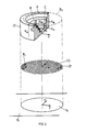
- Fig. 2 schematisch die Zuordnung der abzudampfenden Fläche, eines Strahl-Positionsrasters und eines Korrekturgrössenrasters,
- Fig. 3 eine erweiterte Ausführungsvariante einer erfindungsgemässen Steuerung zur Ausführung des erfindungsgemässen Verfahrens, wobei eine optimale Strahlführungsbahn ermittelt wird,
- Fig. 4 ausgehend von der erfindungsgemässen Steu erung gemäss Fig. 1 eine Weiterausbildung mit mehreren Feldzuordnungs- und Korrekturgrössenspeichern, wobei sich diese, ausgehend von der in Fig. 1 dargestellten Steuerung, mit den Vorkehrungen an der Steuerung gemäss Fig. 3 kombinieren lässt, für eine Strahlbahnoptimierung,
- Fig. 5a, Fig. 5b zwei weitere durch Korrekturgrössenspeicher beispielsweise definierte Korrekturgrössenraster,
- Fig. 6 die Verteilung eines Steuergrössensignals, wie durch die Anordnung gemäss Fig. 4 erzeugt, bei multiplikativem Kreuzpunktoperator an einer Verknüpfungseinheit, und
- Fig. 7 die Verteilung eines Steuergrössensignals, wie es durch eine Verknüpfungseinheit an der Anordnung gemäss Fig. 4, bei additivem Kreuzpunktoperator resultiert.
- 1 shows a combined signal flow function block diagram of a first embodiment variant of a control according to the invention, which operates according to the method according to the invention,
- 2 schematically shows the assignment of the area to be evaporated, a beam position grid and a correction size grid,
- 3 shows an expanded embodiment variant of a control according to the invention for executing the method according to the invention, an optimal beam guidance path being determined,
- Fig. 4 based on the tax according to the
invention 1 further training with several field assignment and correction variable memories, which, starting from the control shown in FIG. 1, can be combined with the precautions on the control according to FIG. 3 for beam path optimization, - 5a, 5b show two further correction-size grids, for example defined by correction-size memories,
- FIG. 6 shows the distribution of a control variable signal, as generated by the arrangement according to FIG. 4, with a multiplicative crosspoint operator on a linking unit, and
- FIG. 7 shows the distribution of a control variable signal, as results from a linking unit on the arrangement according to FIG. 4, with an additive crosspoint operator.
In Fig. 1 ist ein kombiniertes Signalfluss-Funktionsblockdiagramm einer ersten Ausführungsvariante einer erfindungsgemässen Steuerung zur Ausführung des erfindungsgemässen Verfahrens dargestellt.1 shows a combined signal flow function block diagram of a first embodiment variant of a control according to the invention for executing the method according to the invention.
Eine Auslenkungssteuereinheit 1 umfasst einen Positionstaktgeber 1a sowie eine Positionsspeicher 1b. Es seien bezüglich einer abzudampfenden Verdampfungsfläche 14, beispielsweise an einem Tiegel 15, durch ein Positionsraster in Positionen gegeben, die durch den Strahl 12 einer generell mit 3 bezeichne ten Elektronenkanone abzuarbeiten sind. Im Positionsspeicher 1b sind die x, y Werte dieser anzusteuernden Strahlpositionen abgespeichert und ihrer Nummer nach, 1 bis n, an einem Ausgang A₁ ausgebbar. Der Positionstaktgeber 1a aktiviert über seinen Ausgang c1 zyklisch den Positionsspeicher 1b, so dass letzterer an seinem Ausgang A₁ der Reihe nach die jeweils anzusteuernden x, y Werte ausgibt, die der Positionssteuerung 3a der Elektronenkanone 3 zugeführt werden.A
Jedesmal, wenn über den Positionstaktgeber 1a ein nächster Positionswert x,y am Ausgang A₁ der Auslenkungssteuereinheit 1 ausgegeben wird, ist vorerst eine Durchschalteinheit T₁ geöffnet. Es wird das dann am Ausgang A₁ ausgegebene Positionssignal x,y einem Feldzuordnungsspeicher 5 zugeführt. Im Feldzuordnungsspeicher 5 sind jeder der n vorgesehenen Strahlpositionen x, y Feldidentifikationen A, B ... zugeordnet, wobei einer Mehrzahl Positionen x, y jeweils gemeinsam dieselben Feldidentifikationen angehören. Somit umfasst der Feldzuordnungsspeicher 5 wesentlich weniger Feldidentifikationen A, B ... als Strahlpositionen durch die Auslenkungssteuereinheit 1 anzusteuern sind. Durch Zuführung der nachmals anzusteuernden Strahlposition x, y vom Ausgang A₁ an den Feldzuordnungsspeicher 5 wird an seinem Ausgang A₅ die jeweilige Feldidentifikation ausgegeben.Whenever a next position value x, y is output at the
Die Feldidentifikation, die nun am Ausgang A₅ des Feldzuordnungsspeichers 5 ausgegeben wird, wird einem Korrekturgrössenspeicher 7 zugeführt, worin für jede Feldidentifikation A, B ... je ein Korrektur wert KA, KB ... abgespeichert ist und der, entsprechend der am Ausgang A₅ anstehenden Feldidentifikation, am Ausgang A₇ den entsprechenden Korrekturgrössenwert KA, KB etc. ausgibt.The field identification, which is now output at the output A₅ of the
Somit wird, bei immer noch geöffneter Durchschalteinheit T₁, entsprechend der nachmals anzusteuernden x, y Strahlposition, am Ausgang des Korrekturgrössenspeichers 7 der dieser Position entsprechende Korrekturgrössenwert K ausgegeben, welcher dem Feld A bzw. B ... entspricht, worin die genannte Position lokalisiert ist.Thus, with the
Durch das Ausgeben der Korrekturgrösse K am Ausgang A₇ des Korrekturgrössenspeichers 7 wird über einen Impulsformer 9 die Durchschalteinheit T₁ geschlossen, so dass das immer noch am Ausgang A₁ anstehende Positionssignal x, y über eine Halteschaltung 11, welche ebenfalls vom Impulsformer 9 ausgelöst wird, der Positionssteuerung 3a der Elektronenkanone 3 zugeführt wird. Der ausgegebene Korrekturgrössenwert K seinerseits wird über eine Skalierungseinheit 13 als Steuergrössensignal einer Betriebsparameter-Stellgliedeinheit 3b zugespiesen und stellt dort einen Betriebsparameter für die Elektronenkanone 3, wie die Verweilzeit des Elektronenstrahls 12 am nun entsprechend dem anstehenden x,y Wert angesteuerten Punkt an der Verdampfungsfläche 14 oder dessen Fokussierung an diesem Punkt oder dessen Leistung an diesem Punkt.By outputting the correction quantity K at the output A₇ of the
Der Elektronenstrahl 12 arbeitet den nun angesteuerten Punkt ab, während die Durchschalteinheit T₁ wie derum geöffnet ist und durch den vorbeschriebenen Vorgang, erst über Anwahl der nächsten Positionsnummer, dann der neuen Position, der neuen Feldidentifikation und schliesslich der neuen Korrekturgrösse, die Einstellung für den nächsten abzuarbeitenden Punkt vorbereitet wird. Der Positionstaktgeber 1a schaltet, wie dargestellt, zyklisch die Positionsnummern 1 bis n an, so dass die abzudampfende Fläche 14 wiederholt abgearbeitet wird.The
Mittels einer Vorwahleinheit 17 können die Korrekturgrössenwerte K am Korrekturgrössenspeicher 7 eingestellt bzw. vorgewählt werden, bevorzugterweise verstellt, und zwar um einen vorab gespeicherten "Arbeitspunkt" im Korrekturgrössenspeicher 7.By means of a
Bei der derzeitigen Ausführungsvariante der erfindungsgemässen Steuerung wird als Betriebsparameter an der Betriebsparameter-Stellgliedeinheit 3b bevorzugterweise die Verweilzeit des Strahles 12 gestellt.In the current embodiment variant of the control according to the invention, the dwell time of the
Bei der eingesetzten Elektronenkanone handelt es sich weiter z.B. um eine Elektronenkanone bekannter Bauart, wie einer Elektronenkanone ESQ 200 der Firma Balzers AG.The electron gun used is e.g. an electron gun of a known type, such as an electron gun ESQ 200 from Balzers AG.
Anhand von Fig. 2 sei schematisch nochmals das erfindungsgemässe Vorgehen im Zusammenhang mit der in Fig. 1 dargestellten Ausführungsvariante der Steuerung erläutert.The procedure according to the invention in connection with the embodiment variant of the control shown in FIG. 1 is schematically explained again with reference to FIG. 2.
Dabei bezeichnet wiederum die Positionsnummer 14 die gegebene, abzuarbeitende Verdampfungsfläche, beispielsweise im Verdampfungstiegel 15. Der Verdampfungsfläche 14 wird ein Positionsraster 21 für den Elektronenstrahl 12 zugeordnet. Dieses Positionsraster ist in eine Vielzahl gleicher Positionsinkremente 23, welche der Elektronenstrahl 12 ansteuern kann, unterteilt. Wie ersichtlich, geht dabei das Positionsraster 23 bei zunehmender Rasterfeinheit in ein kontinuierliches Raster über, d.h. in diesem Fall kann der Strahl kontinuierlich in jede beliebige Position bezüglich der Fläche 14 gesteuert werden.Here again,
Unabhängig von der Bahn, mit welcher kontinuierlich ode inkrementell der Strahl 12 bezüglich der Verdampfungsfläche 14 geführt ist, wird jeder Position des Strahls 12 relativ zur Fläche 14, entsprechend x, y, eine Korrekturgrösse K zugewiesen, wobei zu betonen ist, dass einer Vielzahl von Strahlpositionen x, y jeweils dieselbe Korrekturgrösse K zugeordnet ist, da eine Vielzahl Positionen dem gleichen Feld A, B ... zugehören. So ist ersichtlich, z.B. gemäss Fig. 2, dass allen Strahlpositionen, welche auf einem äusseren, peripheren Ring-Feld A liegen, die Korrekturgrösse KA zugeordnet ist. Allen Strahlpositionen, welche auf einem anschliessenden, konzentrischen Ring-Feld B liegen, ist die Korrekturgrösse KB zugeordnet und schliesslich weiteren konzentrischen, innenliegenden Ring-Feldern die Korrekturgrösse KC etc.Regardless of the path with which the
Während die Korrekturgrössenwerte K gemäss Fig. 1 bevorzugterweise verstellbar sind, ist bevorzugter weise die Position/Feldzuteilung vorgegeben.1 is preferably adjustable, is more preferred the position / field assignment is specified.
Im Positionsraster 21 ist eine erste Variante einer Strahlbahn bezüglich der Fläche 14 bei B₁ dargestellt. Wird eine solche Bahn B₁ von der Auslenkungssteuerung 1 gemäss Fig. 1 angesteuert, so folgt der Elektronenstrahl 12 einer die Fläche 14 in einem mäanderförmigen Muster abarbeitenden Bahn. Legt man diese Bahn B₁ auf das Korrekturgrössenraster 25, so ist ersichtlich, dass bei einem solchen, aus konzentrischen Kreis-Feldern gebildeten Raster 25 die aus den jeweiligen Korrekturgrössen K resultierende Steuergrösse S₁₃ von Fig. 1 allenfalls unerwünscht häufig geändert wird. Dies kann nun bei Bekanntsein des Korrekturgrössenrasters 25 auf einfache Art und Weise dadurch behoben werden, dass nicht eine mäanderförmige Bahn B₁ gewählt wird, sondern eine Bahn, welche von innen nach aussen oder von aussen nach innen in Kreisbahnen die Fläche 14 abarbeitet.In the
Bei Vorbekanntsein des Korrekturgrössenrasters oder -Profils, wie es in Fig. 2 beispielsweise dargestellt ist, kann nun gezielt an der Auslenkungssteuerung 1 von Fig. 1 eine optimalere Bewegungsbahn vorgegeben werden, wie beispielsweise die in Fig. 2 gestrichelt eingetragene Bahn B₂, wonach jedes der konzentrischen Felder A, B ... erst vollständig abgearbeitet wird, darnach auf das nächste Feld, wie bei B′₂ dargestellt, gesprungen wird, dieses Feld vollständig abgearbeitet wird, etc.If the correction size grid or profile, as is shown in FIG. 2, for example, is known in advance, a more optimal trajectory can now be specified specifically on the
Die Vorgabe einer bestmöglichen Strahlbewegungsbahn, um den Elektronenstrahl 12 möglichst selten und mit möglichst kleinen Stellschritten verstellen zu müssen und um damit, je nach Einstellzeiten, den Prozess zu beschleunigen, ist dann ohne weiteres möglich, wenn das Korrekturgrössenraster vorab bekannt ist. Berücksichtigt man aber, dass, gemäss Fig. 1, individuelle Anpassungen der das Profil des Korrekturgrössenrasters 25 mitbestimmenden Korrekturgrössen K allenfalls möglich sind, so ist ersichtlich, dass nicht in jedem Fall mit einem solchen Vorabkennen des genannten Korrekturgrössenrasters 25 zu rechnen ist. Deshalb wird, wie in Fig. 3 dargestellt, eine weitere Ausführungsvariante der erfindungsgemässen Steuerung vorgeschlagen, bei welcher ein solcher optimaler Weg selbsttätig erst gesucht wird.The specification of the best possible beam movement path around the
In Fig. 3 sind Funktionsblöcke, welche denjenigen von Fig. 1 entsprechen, mit denselben Positionsnummern versehen.In Fig. 3, function blocks which correspond to those of Fig. 1 are provided with the same position numbers.
Der Aufbau der Steuerung gemäss Fig. 3 wird anhand ihrer Funktionsweise erläutert.The structure of the control system according to FIG. 3 is explained on the basis of its mode of operation.
Zu Beginn wird an einer Startpositionsnummer-Vorgabeeinheit 30 eingegeben, an welcher Strahlposition der Bahnermittlungsprozess beginnen soll. Die am Ausgang A₃₀ erscheinende Positionsnummer wird über eine ODER-Verknüpfungseinheit 32 einem Positionsspeicher 1c zugespiesen. Im Positionsspeicher 1c sind die x,y Werte aller durch den Strahl 12 an der Verdampfungsfläche 14 abzuarbeitenden Punkte abgespeichert und sind durch Eingabe der zugeordneten Positionsnummern am Eingang E₁, am Ausgang A₁ aus gebbar.At the start, a starting position
Durch ein Signal am Steuereingang S₁ des Positionsspeichers 1c wird jeweils der Speicherinhalt entsprechend demjenigen x,y Wert gelöscht, dessen Positionsnummer am Eingang E₁ ansteht. Durch ein weiteres Steuersignal U wird der Positionsspeicher 1c zur zyklischen, einmaligen Ausgabe aller in ihm verbleibenden Positionswerte x,y angesteuert.A signal at the
Analog zur Ausführungsvariante von Fig. 1 erscheint nun am Ausgang A₁ der der Startnummer entsprechende Positionswert x, y und wird über eine ODER-Verknüpfungseinheit 34 an den Eingang E₅ des Feldzuordnungsspeichers 5 gespiesen, worauf letzterer die der Position entsprechende Feldidentifikation A, B ... am Ausgang A₅ ausgibt. Die Feldidentifikation wird nun vom Ausgang A₅ an den Eingang E₇ des Korrekturgrössenspeichers 7 gespiesen, worauf letzterer in vorbeschriebener Art und Weise die dem identifizierten Feld entsprechende Korrekturgrösse KA bzw. KB ... am Ausgang A₇ abgibt.Analogous to the embodiment of FIG. 1, the position value x, y corresponding to the start number now appears at the output A₁ and is fed via an OR
Bei Erscheinen der Startnummer am Eingang E₁ des Positionsspeichers 1c wird, beispielsweise über einen Impulsformer 36, eine Zeitverzögerung 38 und eine bistabile Einheit 40, eine Umschaltereinheit T₂ in die in Fig. 3 ausgezogen dargestellte Position geschaltet, und der am Ausgang A₇ erscheinende Korrekturgrössenwert einem Momentanwertspeicher 42 eingegeben. Sobald dieser Korrekturgrössenwert im Momentanwertspeicher 42 eingegeben ist und an dessen Ausgang A₄₂ erscheint, wird, beispielsweise über einen Impulsformer 44, die bistabile Einheit 40 rückgesetzt, worauf die Umschaltereinheit T2 in die gestrichelt dargestellte Position rückfällt.When the start number appears at the input E₁ of the position memory 1c, for example via a
Der Ausgangsimpuls des Impulsformers 44 wird weiter dem Rücksetzeingang S₁ zugespiesen, wodurch der Speicherinhalt des Positionsspeichers 1c gelöscht wird, der durch die am Eingang E₁ anstehende Positionsnummer definiert ist. Mithin wird bei Erscheinen des im Momentanwertspeicher 42 eben abgespeicherten Korrekturgrössenwertes am Positionsspeicher 1c der der Startposition entsprechende Speicherinhalt gelöscht. Dieser Positionswert ist aber nicht verloren, denn er wurde während der momentanen Abspeicherung der zugehörigen Korrekturgrösse, durch Schliessen einer Durchschalteinheit T₃ und in gestrichelter Position geschalteter Durchschalteinheit T₄, einem Optimalbahn-Positionsspeicher 48 eingegeben. Dies erfolgte durch Schliessen der Durchschalteinheit T₃ mit dem auch die Umschalteinheit T₂ auf den Speicher 42 schaltenden Ausgangssignal der bistabilen Einheit 40.The output pulse of the
Nach Umlegen der Umschalteinheit T2 in die gestrichelt dargestellte Position ist somit der Speicherinhalt entsprechend der Startpositionsnummer im Positionsspeicher 1c gelöscht, ist aber im Optimalbahn-Positionsspeicher 48 abgelegt.After switching the switchover unit T2 into the position shown in dashed lines, the memory content corresponding to the start position number in the position memory 1c is thus deleted, but is stored in the optimum path position
Durch den Impuls der Einheit 44 wird der Steuereingang U zum Positionsspeicher 1c angesteuert, worauf der Positionsspeicher 1c in einem Zyklus alle verbleibenden x,y Positionswerte an seinen Ausgang A₁ ausgibt. Ueber die ODER-Verknüpfungseinheit 34, den Feldzuordnungsspeicher 5 und den Korrekturgrössenspeicher 7, eine in ausgezogener Position geschaltete Umschalteinheit T5 werden somit zyklisch alle den im Positionsspeicher 1c verbleibenden Positionen entsprechenden Korrekturgrössenwerte K einer Differenzeinheit 50 zugeführt, zusammen mit dem im Momentanwertspeicher 42 abgelegten Korrekturgrössenwert.By the pulse of the
Die Differenz Δ der Korrekturgrössen K aller im Positionsspeicher 1c verbleibenden Positionen werden einer Differenzspeichereinheit 52 zugeführt, und zwar gleichzeitig mit der dem Positionsspeicher 1c entnommenen, jeweiligen Positionsnummer m, wobei im Speicher 52 jeweils eine Korrekturgrössendifferenz ΔK mit der Nummer der Position m abgespeichert wird, deren Korrekturgrösse mit der im Speicher 42 abgelegten Korrekturgrösse in Beziehung gesetzt wurde.The difference Δ of the correction quantities K of all positions remaining in the position memory 1c are fed to a
Nachdem am Ausgang A₁ des Positionsspeichers 1c alle verbleibenden Positionen ausgegeben wurden, ist somit im Differenzspeicher 52 die folgende Funktion abgelegt: Korrekturgrössenwertdifferenz aller Korrekturgrössen, welche den im Positionsspeicher 1c verbleibenden Positionen entsprechen, zu dem der Startposition entsprechenden Korrekturgrössenwert in Funktion der Positionsnummer m. Diese Funktion ΔKm, die nach einmaligem Umwälzen des Positionsspeichers 1c im Differenzspeicher 52 liegt, wird einer Minimumbestimmungseinheit 54 zugespiesen, welche detektiert, bei welcher Positionsnummer mmin die Differenz ΔKm im Differenzspeicher 52 minimal ist. Diese Positionsnummer mmin wird der ODER-Einheit 32 zugespiesen, dann dem Eingang E₁ des Positionsspeichers 1c. Diese neu gefundene Positionsnummer wirkt nun genau gleich wie die vorab zum Starten des Prozesses eingegebene Startnummer von Ausgang A₃₀:After all the remaining positions have been output at the
Entsprechend der Nummer mmin erscheint am Ausgang des Positionsspeichers 1c die zugeordnete x,y Position, wird über die ODER-Verknüpfungseinheit 34 dem Feldzuordnungsspeicher 5 zugespiesen, dessen Ausgang dem Korrekturgrössenspeicher 7, dessen Ausgang wiederum erst dem Momentanwertspeicher 42, wo er zwischengespeichert wird. Der ausgegebene Positionswert am Ausgang A₁ wird weiter dem Optimalbahn-Positionsspeicher 48 als nächste Position x2′, y2′ zugespiesen, darnach im Positionsspeichers 1c mit wird, durch Umwälzen des Positionsspeicher 1c gelöscht. Dann den noch verbleibenden Positionswerten, wiederum die Korrekturgrössendifferenz in Funktion der im Positionsspeicher 1c verbleibenden Positionsnummern im Speicher 52 abgelegt, darnach an der Minimumbestimmungseinheit 54 die neue Minimum-Nummer mmin ermittelt etc.Corresponding to the number m min , the assigned x, y position appears at the output of the position memory 1c, is fed via the
Wie ersichtlich, verbleibt im Positionsspeicher 1c nach jedem derartigen Umgang eine Positionsnummer mit den entsprechenden Positions-x,y-Werten weniger, bis alle vormals im Positionsspeicher 1c abgespeicherten Positions-x,y-Werte, in neuer Reihenfolge, im Optimalbahn-Positionsspeicher 48 abgelegt sind. Die nun in diesem Speicher 48 abgelegte Positionsreihenfolge entspricht einer Bewegungsbahn für den Strahl 12 der Elektronenkanone 3, bei welcher si chergestellt ist, dass, von Position zu Position fortschreitend, jeweils minimale Korrekturgrössenschritte durchgeführt werden müssen.As can be seen, a position number with the corresponding position x, y values less remains in the position memory 1c after each such handling, until all position x, y values previously stored in the position memory 1c are stored in the optimum path position
Ein Zähler 56 zählt, wie oft der Momentanwertspeicher 42 geladen wurde, und steuert, sobald sein Zählstand der Anzahl anzusteuernder Strahlpositionen n entspricht, eine bistabile Einheit 58 an. Dies zeigt an, dass die erwähnte optimale Bahn im Optimalbahnspeicher 48 abgelegt ist. Nun ist der Suchprozess für diese optimale Bahn abgeschlossen, und der nun einsetzende Positioniervorgang für den Strahl 12 der Elektronenkanone 3 wird, ausgehend von diesem Optimalbahnspeicher 48 angesteuert, der nun anstelle des Positionsspeichers 1c tritt: Das Ausgangssignal der bistabilen Einheit 58 öffnet hierzu die Durchschalteinheit T₄ und schliesst eine weitere Durchschalteinheit T₆ ausgangsseitig des Optimalbahn-Positionsspeichers 48, womit dessen Ausgang A₄₈ auf die ODER-Verknüpfungseinheit 34 geschaltet wird. Gleichzeitig wird der Ausgang A₄₈ durch Schliessen der Durchschalteinheit T₆ auf den Positionssteuereingang an der Elektronenkanone 3 geführt. Ebenfalls durch das Ausgangssignal A₅₈ der bistabilen Einheit 58 wird die Umschaltereinheit T₅ in die gestrichelt dargestellte Position gelegt, womit der Ausgang A₇ des Korrekturgrössenspeichers 7 über die Skalierungseinheit 9 der Betriebsparameterstellereinheit 3b der Elektronenkanone 3 zugespiesen wird.A counter 56 counts the number of times the
Durch das Ausgangssignal A₅₈ der bistabilen Einheit 48 wird weiter ein Taktgeber 60 ausgelöst, dessen Ausgangssignal A₆₀ nun der Reihe nach, und somit der optimalen Bahn entsprechend, die Positionssignale aus dem Optimalbahn-Positionsspeicher 48 austaktet, womit einerseits, über die Positionssteuerung 3a die Elektronenkanone 12 dieser Optimalbahn folgt, und anderseits, über die ODER-Verknüpfungseinheit 34, den Feldzuordnungsspeicher 5 und den Korrekturgrössenspeicher 7 jeweils der gewählte Betriebsparameter, wie die Strahlverweilzeit, dessen Fokussierung oder Leistung, an der Betriebsparameterstellereinheit 3b gestellt wird.A
In gewissen Fällen kann es Z.B. aus Gründen von Mehrdeutigkeiten bezüglich des Minimums, das an der Minimumbestimmungseinheit 54 aufzufinden ist, angezeigt sein, vorab die Anzahl Punkte, bezüglich welcher die Korrekturgrössendifferenzen ΔK zu bilden sind, einzuschränken. Ein solches Einschränkungskriterium kann dabei sein, dass nur die Korrekturgrössendifferenzen von Punkten zu bilden sind, die in den x- und y-Koordinaten einander benachbart sind. Hierzu wird dann jeweils der Positionsspeicher 1c nicht zum Umwälzen aller in ihm verbleibenden Speicherinhalte mit dem Steuersignal U angesteuert, sondern es werden jeweils nur die in x und y nächst numerierten Positionen zur Differenzbildung angesteuert. Dies heisst, dass, wenn im Momentanspeicher 42 ein dem Punkt xr, yr entsprechender Korrekturwert abgelegt ist, diesbezüglich nur die Differenzen entsprechend den Punkten xr±1, yr bzw. xr, yr±1 untersucht werden, allenfalls auch die Punkte xr±1, yr±1.In certain cases, for example, for reasons of ambiguity regarding the minimum that can be found at the
In Fig. 4 ist eine weitere Ausführungsvariante der erfindungsgemässen Anlage, ausgehend von ihrer Kon figuration gemäss Fig. 1, dargestellt, d.h. mit vorgegebener Strahlbahnführung. Wie ersichtlich werden wird, ist es gerade bei einer solchen Weiterbildung möglicherweise angezeigt, die Anlage mit den die optimale Strahlbahn suchenden Vorkehrungen, wie sie anhand von Fig. 3 dargestellt wurden, auszubauen, wobei dieser Ausbau in Analogie zur Darstellung von Fig. 3 erfolgt.4 shows a further embodiment variant of the system according to the invention, starting from its con Figure according to Fig. 1, shown, ie with a given beam path. As will be seen, it may be indicated with such a further development to expand the system with the arrangements searching for the optimal beam path, as were shown with reference to FIG. 3, this expansion taking place in analogy to the illustration in FIG. 3.
Funktionsblöcke und Signale, die denjenigen von Fig. 1 entsprechen, sind in Fig. 4 mit denselben Positionszeichen versehen.Function blocks and signals which correspond to those of FIG. 1 are provided with the same position symbols in FIG. 4.
Bei der Ausbildungsvariante gemäss Fig. 4 gibt die Auslenkungssteuerung 1, betrieben wie die in Fig. 1 dargestellte, an ihrem Ausgang A₁ und getaktet vom Positionstaktgeber 1a das jeweilige Positionssignal x,y ab. Es ist nun eine Mehrzahl einander zugehöriger Sätze jeweils eines Feldzuordnungsspeichers und eines Korrekturgrössenspeichers 5a/7a, 5b/7b etc. vorgesehen. Allen anzusteuernden n Strahlpositionen x, y sind in jedem dieser Sätze eine Feldverteilung zugeordnet, so beispielsweise im Satz "a" die Felder Aa, Ba ..., Da und im Satz "b" die Felder Ab, Bb ..., Cb, die im allgemeinen Fall nicht übereinstimmen. Diesen satzspezifischen Feldern sind in den zugeordneten Korrekturgrössenspeichern 7a bzw. 7b die entsprechenden Korrekturgrössen K beigefügt.4, the
Es sind zwei oder mehr derartiger Feldzuordnungs-/Korrekturgrössenspeicher-Sätze vorgesehen, welche je einzeln oder in beliebigen Kombinationen für einen jeweilig anzusteuernden Abarbeitungsprozess aufge schaltet werden können. Hierzu sind schematisch dargestellte Zuschalt-Anordnungen 70 vorgesehen, mittels welcher einerseits der Ausgang A₁ in Analogie zu den Ausführungen von Fig. 1, nun aber selektiv, einem oder mehreren der Feldzuordnungsspeicher 5 zugeschaltet werden kann. Entsprechend werden die Ausgänge A₇ eines oder mehrerer der vorgesehenen Sätze 5/7 auf eine Verknüpfungseinheit 72 geschaltet.Two or more such field assignment / correction variable memory sets are provided, each of which is set up individually or in any combination for a particular processing process to be controlled can be switched. For this purpose, schematically illustrated connection arrangements 70 are provided, by means of which on the one hand the
An der Verknüpfungseinheit werden alle an den jeweils aktivierten Ausgängen A₇ ausgegebenen Korrekturgrössen miteinander verknüpft, bevorzugterweise allenfalls gewichtet addiert oder multipliziert, so dass am Ausgang A₇₂ der Verknüpfungseinheit 72 ein Signal auftritt, über die Skalierungseinheit 13, in das Stellsignal S₁₃ gewandelt, das eine Funktion der Korrekturgrösse(n) ein oder mehrerer, der aufgeschalteten Feldzuordnungs-/Korrekturgrössenspeicher-Sätze 5/7 ist.At the linking unit, all of the correction variables output at the respectively activated outputs A verknüpft are linked to one another, preferably weighted added or multiplied, so that a signal occurs at the output A₇₂ of the linking
In jedem der vorgesehenen Sätze 5/7 ist ein vorzugsweise dem Einfluss einer physikalischen Grösse auf die Wirkung des Elektronenstrahls 12 bezüglich der abzudampfenden Fläche 14 entsprechendes Korrekturgrössenraster in Analogie zum Korrekturgrössenraster 25 von Fig. 2 abgespeichert. So sind beispielsweise im Feldzuordnungs-/Korrekturgrössenspeicher-Satz "a" die Felder und Korrekturgrössen eines Kreisringfeld-Korrekturgrössenrasters, wie in Fig. 2 dargestellt, abgespeichert. Ein Korrekturgrössenraster mit diesem Profil trägt, an einem axialsymmetrischen Verdampfungstiegel, den thermischen Diffusionsverhältnissen zur gekühlten Tiegelaussenwand Rechnung, die mittels kreisringförmiger Isothermen darstellbar sind.In each of the provided sets 5/7, a correction size grid, preferably corresponding to the influence of a physical quantity on the effect of the
Im zweiten Feldzuordnungs-/Korrekturgrössenspeicher-Satz "b" sind beispielsweise Feld- und Korrekturgrössenverhältnisse abgespeichert, die ein Korrekturgrössenraster, wie es in Fig. 5a dargestellt ist, definieren, welches dem Einfluss der sich ändernden Fokussierung bei der Ablenkung eines Elektronenstrahls Rechnung trägt, der zwischen Elektronenstrahlquelle und Verdampfungsfläche 14 eine 270° Umlenkung erfährt, in einer senkrecht zur Verdampfungsfläche stehenden Ebene, z.B. durch die y-Achse.In the second field assignment / correction quantity memory set "b", for example, field and correction quantity relationships are stored, which define a correction quantity grid, as shown in FIG. 5a, which takes into account the influence of the changing focusing during the deflection of an electron beam, which undergoes a 270 ° deflection between the electron beam source and the
Durch einen weiteren, in Fig. 4 nicht dargestellten Feldzuordnungs-/Korrekturgrössenspeicher-Satz wird beispielsweise ein Korrekturgrössenraster mit dem Profil gemäss Fig. 5b definiert, welches, mit sichelförmigen Feldern, dem Einfluss der seitlichen Ablenkung in x-Richtung, beispielsweise der erwähnten Elektronenstrahlkanone, Rechnung trägt, bei der ab Elektronenstrahlquelle der Strahl erst um 270° in einer Ebene senkrecht zur Abdampfebene 14 und durch die eingezeichnete y-Achse umgelenkt wird.A further field assignment / correction variable memory set, not shown in FIG. 4, defines, for example, a correction variable grid with the profile according to FIG. 5 b, which, with sickle-shaped fields, influences the lateral deflection in the x direction, for example the aforementioned electron beam gun. Takes into account, in which the beam is deflected only by 270 ° in a plane perpendicular to the
Wie in Fig. 4 dargestellt, wird durch die Zuschaltanordnung 70 festgelegt, welche der Korrekturgrössenraster bei einem beabsichtigten Verdampfungsprozess eingesetzt werden sollen. Dabei ist nochmals zu betonen, dass jeweils eine Strahlposition x,y in jedem Satz einem anderen Feld zugehören kann und mithin an jedem Satz eine andere Korrekturgrösse abruft, und dass alle Korrekturgrössen - ein oder mehrere - zur Bildung des Stellsignals S₁₃ schliesslich an der Verknüpfungseinheit 72 vorzugsweise multiplikativ oder additiv miteinander verknüpft werden.As shown in FIG. 4, the connection arrangement 70 determines which of the correction size grids are to be used in an intended evaporation process. It should be emphasized again that a beam position x, y in each set can belong to a different field and therefore retrieves a different correction quantity at each set, and that all correction quantities - one or more - finally form the actuating signal S₁₃ are preferably linked multiplicatively or additively to one another at the linking
In Fig. 6 ist das Steuergrössensignal S₁₃ dargestellt, wenn zwei Feldzuordnungs-/Korrekturgrössenspeicher-Sätze 5/7 eingesetzt sind, wobei mit dem einen Satz ein Korrekturgrössenraster, wie bei 74 dargestellt, definiert werde, mit dem anderen Satz ein Korrekturgrössenraster wie bei 76 dargestellt. Bei Auslegung der Verknüpfungseinheit 72 von Fig. 4 als Multiplikationseinheit, woran die den Feldern zugeordneten Korrekturgrössenwerte K miteinander multipliziert werden, ergibt sich ein Verlauf des Steuergrössensignals S₁₃ über der x,y Ebene, d.h. eigentlich der Verdampfungsfläche 14, wie bei 78 in Fig. 6 dargestellt ist. Bei additiver Verknüpfung an der Verknüpfungseinheit 72 ergibt sich bei den in Fig. 7 dargestellten Korrekturgrössenrastern 80 und 82 ein Steuergrössensignalverlauf über der Verdampfungsfläche 14, wie bei 84 dargestellt.In Fig. 6, the control quantity signal S₁₃ is shown when two field assignment / correction quantity memory sets 5/7 are used, with one set a correction quantity grid, as shown at 74, is defined, with the other set a correction quantity grid as shown at 76 . 4, as a multiplication unit, by which the correction variable values K assigned to the fields are multiplied with one another, there is a profile of the control variable signal S₁₃ over the x, y plane, i.e. actually the
Nach erster Abschätzung der Korrekturgrössen, anhand physikalischer Symmetrien, wie bezüglich Wärmediffusion, werden genauere Grössen bevorzugterweise durch das Experiment festgelegt und festgehalten.After the first estimation of the correction quantities, based on physical symmetries, such as with regard to heat diffusion, more precise quantities are preferably determined and recorded by the experiment.
Claims (14)
- die Ablenkungssteuerung (1) ein Positionsidentifikationssignal (Nr) abgibt, das eine Strahlposition (x, y) identifiziert, welche einer Position auf der Fläche (14) entspricht, die noch weniger abgearbeitet ist als andere Positionen der Fläche des Tiegels,
- Speichermittel (7) für das Abspeichern von Korrekturgrössen (K) für Strahlbetriebsparameter vorgesehen sind,
- Zuordnungsmittel (5) vorgesehen sind, die Speicherstellen der Speichermittel (7) mit derselben Korrekturgrösse (K) zuordnen und ausgeben,
- die ausgegebenen Korrekturgrössen (K) als Steuergrösse (S₁₃) auf mindestens einen Steuereingang der Steuereinheit (3b) geführt sind,
- die Ablenkungssteuerung (1) den Strahl (12) in eine nächste Position steuert.8. Electron beam control for evaporation System with a deflection control (1) for the jet (12), which controls the jet position (x, y) for processing an evaporation surface (14) via the latter, and with a control unit (3b) for controlling jet operating parameters, characterized in that
the deflection controller (1) emits a position identification signal (Nr) which identifies a beam position (x, y) which corresponds to a position on the surface (14) which is even less processed than other positions on the surface of the crucible,
Storage means (7) are provided for storing correction parameters (K) for beam operating parameters,
Allocation means (5) are provided which allocate and output the storage locations of the storage means (7) with the same correction variable (K),
- The output correction variables (K) are performed as a control variable (S₁₃) on at least one control input of the control unit (3b),
- The deflection control (1) controls the beam (12) in a next position.
Applications Claiming Priority (2)
| Application Number | Priority Date | Filing Date | Title |
|---|---|---|---|
| CH4172/88 | 1988-11-10 | ||
| CH417288 | 1988-11-10 |
Publications (2)
| Publication Number | Publication Date |
|---|---|
| EP0368037A1 true EP0368037A1 (en) | 1990-05-16 |
| EP0368037B1 EP0368037B1 (en) | 1994-07-06 |
Family
ID=4271145
Family Applications (1)
| Application Number | Title | Priority Date | Filing Date |
|---|---|---|---|
| EP89119229A Expired - Lifetime EP0368037B1 (en) | 1988-11-10 | 1989-10-17 | Process for controlling the distribution of the evaporation rate of an electron beam |
Country Status (5)
| Country | Link |
|---|---|
| US (1) | US5003151A (en) |
| EP (1) | EP0368037B1 (en) |
| JP (1) | JP2878340B2 (en) |
| AT (1) | ATE108283T1 (en) |
| DE (1) | DE58908004D1 (en) |
Cited By (1)
| Publication number | Priority date | Publication date | Assignee | Title |
|---|---|---|---|---|
| EP0910110A2 (en) * | 1997-10-16 | 1999-04-21 | Balzers und Leybold Deutschland Holding AG | Method for operating a high power electron beam |
Families Citing this family (5)
| Publication number | Priority date | Publication date | Assignee | Title |
|---|---|---|---|---|
| US6215127B1 (en) * | 1999-03-08 | 2001-04-10 | Advanced Micro Devices, Inc. | Method of using critical dimension mapping to qualify a new integrated circuit fabrication tool set |
| EP1275750B1 (en) * | 2001-07-11 | 2009-07-01 | Carl Zeiss Vision GmbH | Vapor deposition apparatus |
| DE102016122671A1 (en) * | 2016-11-24 | 2018-05-24 | VON ARDENNE Asset GmbH & Co. KG | Method and electron gun |
| DE102018101821A1 (en) * | 2018-01-26 | 2019-08-01 | VON ARDENNE Asset GmbH & Co. KG | Method, electron gun and control device |
| DE102018103079A1 (en) * | 2018-02-12 | 2019-08-14 | VON ARDENNE Asset GmbH & Co. KG | Method, electron gun and control device |
Citations (3)
| Publication number | Priority date | Publication date | Assignee | Title |
|---|---|---|---|---|
| EP0104922A2 (en) * | 1982-09-27 | 1984-04-04 | Fujitsu Limited | Electron beam exposure system |
| DE3428802A1 (en) * | 1984-08-04 | 1986-02-13 | Leybold-Heraeus GmbH, 5000 Köln | METHOD AND DEVICE FOR CONTROLLING THE FOCUSING STATE OF A DEFLECTED ELECTRON BEAM |
| EP0222219A2 (en) * | 1985-11-02 | 1987-05-20 | Leybold Aktiengesellschaft | Device for the bombardment of a medium with an electron beam |
Family Cites Families (3)
| Publication number | Priority date | Publication date | Assignee | Title |
|---|---|---|---|---|
| US3607222A (en) * | 1968-11-26 | 1971-09-21 | Air Reduction | Method for evaporating alloy |
| US3875416A (en) * | 1970-06-30 | 1975-04-01 | Texas Instruments Inc | Methods and apparatus for the production of semiconductor devices by electron-beam patterning and devices produced thereby |
| CA1288733C (en) * | 1985-09-05 | 1991-09-10 | The Black Clawson Company | Apparatus for screening paper fiber stock |
-
1989
- 1989-10-17 DE DE58908004T patent/DE58908004D1/en not_active Expired - Fee Related
- 1989-10-17 AT AT89119229T patent/ATE108283T1/en not_active IP Right Cessation
- 1989-10-17 EP EP89119229A patent/EP0368037B1/en not_active Expired - Lifetime
- 1989-11-08 US US07/433,609 patent/US5003151A/en not_active Expired - Lifetime
- 1989-11-10 JP JP1291377A patent/JP2878340B2/en not_active Expired - Fee Related
Patent Citations (3)
| Publication number | Priority date | Publication date | Assignee | Title |
|---|---|---|---|---|
| EP0104922A2 (en) * | 1982-09-27 | 1984-04-04 | Fujitsu Limited | Electron beam exposure system |
| DE3428802A1 (en) * | 1984-08-04 | 1986-02-13 | Leybold-Heraeus GmbH, 5000 Köln | METHOD AND DEVICE FOR CONTROLLING THE FOCUSING STATE OF A DEFLECTED ELECTRON BEAM |
| EP0222219A2 (en) * | 1985-11-02 | 1987-05-20 | Leybold Aktiengesellschaft | Device for the bombardment of a medium with an electron beam |
Cited By (6)
| Publication number | Priority date | Publication date | Assignee | Title |
|---|---|---|---|---|
| EP0910110A2 (en) * | 1997-10-16 | 1999-04-21 | Balzers und Leybold Deutschland Holding AG | Method for operating a high power electron beam |
| DE19745771A1 (en) * | 1997-10-16 | 1999-04-29 | Leybold Ag | Process for operating a high power electron beam |
| EP0910110A3 (en) * | 1997-10-16 | 2000-12-27 | Balzers und Leybold Deutschland Holding AG | Method for operating a high power electron beam |
| US6214408B1 (en) | 1997-10-16 | 2001-04-10 | Balzers Und Leybold Deutschland Holding Ag | Method for the operation of an electron beam |
| US6436466B2 (en) | 1997-10-16 | 2002-08-20 | Unaxis Deutschland Holding Gmbh | Method for the operation of an electron beam |
| DE19745771B4 (en) * | 1997-10-16 | 2005-12-22 | Unaxis Deutschland Holding Gmbh | Method for operating a high-power electron beam |
Also Published As
| Publication number | Publication date |
|---|---|
| JPH03160713A (en) | 1991-07-10 |
| EP0368037B1 (en) | 1994-07-06 |
| DE58908004D1 (en) | 1994-08-11 |
| JP2878340B2 (en) | 1999-04-05 |
| ATE108283T1 (en) | 1994-07-15 |
| US5003151A (en) | 1991-03-26 |
Similar Documents
| Publication | Publication Date | Title |
|---|---|---|
| DE1053691B (en) | Method and device for material processing using a charge carrier beam | |
| DE3444161C2 (en) | ||
| EP0885348B1 (en) | Process and device for rapid power control of a power station | |
| EP0368037B1 (en) | Process for controlling the distribution of the evaporation rate of an electron beam | |
| DE3546130C2 (en) | Process for controlling machining in an electrical discharge machine with a wire electrode | |
| DE102007012370A1 (en) | Vapor deposition device and vapor deposition method for molecular beam deposition and molecular beam epitaxy | |
| DE3809630C1 (en) | ||
| EP3071343B1 (en) | Operating method for a cooling section and cooling section | |
| DE4111106A1 (en) | MULTI-PRESSURE CONTROL SYSTEM | |
| DE2747237A1 (en) | WORKPIECE TRANSPORT DEVICE | |
| DE3525177A1 (en) | METHOD AND DEVICE FOR MELTING AND EVAPORATING HIGH PURITY SILICON | |
| DE4305870C2 (en) | Process water temperature control | |
| EP0335122B1 (en) | Device and procedure for controlling and monitoring electron beam for processing metals | |
| CH665307A5 (en) | DEVICE FOR CONTACTLESSLY GENERATING A LOCAL VACUUM ON A WORKPIECE. | |
| WO2005106071A2 (en) | Continuous thermal vacuum deposition device and method | |
| DE10051508C2 (en) | Method and device for reducing the ignition voltage of power pulses of pulsed plasmas | |
| DE2739412A1 (en) | THREAD FEED AND CHANGING DEVICE | |
| DE3538857A1 (en) | DEVICE FOR ENTERING A SET POINT FOR THE HIT POINT OF AN ELECTRON BEAM ON A MEDIUM | |
| DE3545957A1 (en) | Method and circuit arrangement for automatically processing setting-up functions in numeric controls | |
| DE2841969C2 (en) | Evaporation crucible for the evaporation of alloys with components with different vapor pressures | |
| EP0735445B1 (en) | Method for the operation of a machine-tool or a robot | |
| DE4026119C2 (en) | Method for controlling a punching machine with two processing heads | |
| DE1615449C2 (en) | Device for the thermal surface treatment of metallic workpieces by means of electron beams | |
| CH658213A5 (en) | METHOD AND DEVICE FOR SPARK-EDMING WORKPIECES. | |
| EP0654155B1 (en) | Device for controlling the switchover of processor operation from an instantaneous status to a follow-on status |
Legal Events
| Date | Code | Title | Description |
|---|---|---|---|
| PUAI | Public reference made under article 153(3) epc to a published international application that has entered the european phase |
Free format text: ORIGINAL CODE: 0009012 |
|
| AK | Designated contracting states |
Kind code of ref document: A1 Designated state(s): AT BE CH DE ES FR GB GR IT LI LU NL SE |
|
| 17P | Request for examination filed |
Effective date: 19900531 |
|
| 17Q | First examination report despatched |
Effective date: 19921019 |
|
| GRAA | (expected) grant |
Free format text: ORIGINAL CODE: 0009210 |
|
| AK | Designated contracting states |
Kind code of ref document: B1 Designated state(s): AT BE CH DE ES FR GB GR IT LI LU NL SE |
|
| PG25 | Lapsed in a contracting state [announced via postgrant information from national office to epo] |
Ref country code: GR Free format text: LAPSE BECAUSE OF FAILURE TO SUBMIT A TRANSLATION OF THE DESCRIPTION OR TO PAY THE FEE WITHIN THE PRESCRIBED TIME-LIMIT Effective date: 19940706 Ref country code: ES Free format text: THE PATENT HAS BEEN ANNULLED BY A DECISION OF A NATIONAL AUTHORITY Effective date: 19940706 |
|
| REF | Corresponds to: |
Ref document number: 108283 Country of ref document: AT Date of ref document: 19940715 Kind code of ref document: T |
|
| GBT | Gb: translation of ep patent filed (gb section 77(6)(a)/1977) |
Effective date: 19940704 |
|
| REF | Corresponds to: |
Ref document number: 58908004 Country of ref document: DE Date of ref document: 19940811 |
|
| ET | Fr: translation filed | ||
| ITF | It: translation for a ep patent filed |
Owner name: ING. ZINI MARANESI & C. S.R.L. |
|
| PG25 | Lapsed in a contracting state [announced via postgrant information from national office to epo] |
Ref country code: SE Effective date: 19941006 |
|
| PLBE | No opposition filed within time limit |
Free format text: ORIGINAL CODE: 0009261 |
|
| STAA | Information on the status of an ep patent application or granted ep patent |
Free format text: STATUS: NO OPPOSITION FILED WITHIN TIME LIMIT |
|
| 26N | No opposition filed | ||
| PGFP | Annual fee paid to national office [announced via postgrant information from national office to epo] |
Ref country code: LU Payment date: 20011009 Year of fee payment: 13 |
|
| REG | Reference to a national code |
Ref country code: GB Ref legal event code: IF02 |
|
| PGFP | Annual fee paid to national office [announced via postgrant information from national office to epo] |
Ref country code: AT Payment date: 20021011 Year of fee payment: 14 |
|
| PG25 | Lapsed in a contracting state [announced via postgrant information from national office to epo] |
Ref country code: LU Free format text: LAPSE BECAUSE OF NON-PAYMENT OF DUE FEES Effective date: 20021017 |
|
| PGFP | Annual fee paid to national office [announced via postgrant information from national office to epo] |
Ref country code: NL Payment date: 20021031 Year of fee payment: 14 |
|
| PGFP | Annual fee paid to national office [announced via postgrant information from national office to epo] |
Ref country code: BE Payment date: 20021219 Year of fee payment: 14 |
|
| PG25 | Lapsed in a contracting state [announced via postgrant information from national office to epo] |
Ref country code: AT Free format text: LAPSE BECAUSE OF NON-PAYMENT OF DUE FEES Effective date: 20031017 |
|
| PG25 | Lapsed in a contracting state [announced via postgrant information from national office to epo] |
Ref country code: BE Free format text: LAPSE BECAUSE OF NON-PAYMENT OF DUE FEES Effective date: 20031031 |
|
| BERE | Be: lapsed |
Owner name: *BALZERS A.G. Effective date: 20031031 |
|
| PG25 | Lapsed in a contracting state [announced via postgrant information from national office to epo] |
Ref country code: NL Free format text: LAPSE BECAUSE OF NON-PAYMENT OF DUE FEES Effective date: 20040501 |
|
| NLV4 | Nl: lapsed or anulled due to non-payment of the annual fee |
Effective date: 20040501 |
|
| PGFP | Annual fee paid to national office [announced via postgrant information from national office to epo] |
Ref country code: FR Payment date: 20041008 Year of fee payment: 16 |
|
| PGFP | Annual fee paid to national office [announced via postgrant information from national office to epo] |
Ref country code: GB Payment date: 20041013 Year of fee payment: 16 |
|
| PGFP | Annual fee paid to national office [announced via postgrant information from national office to epo] |
Ref country code: DE Payment date: 20041014 Year of fee payment: 16 |
|
| PGFP | Annual fee paid to national office [announced via postgrant information from national office to epo] |
Ref country code: CH Payment date: 20050124 Year of fee payment: 16 |
|
| PG25 | Lapsed in a contracting state [announced via postgrant information from national office to epo] |
Ref country code: IT Free format text: LAPSE BECAUSE OF NON-PAYMENT OF DUE FEES;WARNING: LAPSES OF ITALIAN PATENTS WITH EFFECTIVE DATE BEFORE 2007 MAY HAVE OCCURRED AT ANY TIME BEFORE 2007. THE CORRECT EFFECTIVE DATE MAY BE DIFFERENT FROM THE ONE RECORDED. Effective date: 20051017 Ref country code: GB Free format text: LAPSE BECAUSE OF NON-PAYMENT OF DUE FEES Effective date: 20051017 |
|
| PG25 | Lapsed in a contracting state [announced via postgrant information from national office to epo] |
Ref country code: LI Free format text: LAPSE BECAUSE OF NON-PAYMENT OF DUE FEES Effective date: 20051031 Ref country code: CH Free format text: LAPSE BECAUSE OF NON-PAYMENT OF DUE FEES Effective date: 20051031 |
|
| PG25 | Lapsed in a contracting state [announced via postgrant information from national office to epo] |
Ref country code: DE Free format text: LAPSE BECAUSE OF NON-PAYMENT OF DUE FEES Effective date: 20060503 |
|
| REG | Reference to a national code |
Ref country code: CH Ref legal event code: PL |
|
| GBPC | Gb: european patent ceased through non-payment of renewal fee |
Effective date: 20051017 |
|
| PG25 | Lapsed in a contracting state [announced via postgrant information from national office to epo] |
Ref country code: FR Free format text: LAPSE BECAUSE OF NON-PAYMENT OF DUE FEES Effective date: 20060630 |
|
| REG | Reference to a national code |
Ref country code: FR Ref legal event code: ST Effective date: 20060630 |