EP0367113B1 - Bolster apparatus for press-forming workpieces - Google Patents
Bolster apparatus for press-forming workpieces Download PDFInfo
- Publication number
- EP0367113B1 EP0367113B1 EP89119919A EP89119919A EP0367113B1 EP 0367113 B1 EP0367113 B1 EP 0367113B1 EP 89119919 A EP89119919 A EP 89119919A EP 89119919 A EP89119919 A EP 89119919A EP 0367113 B1 EP0367113 B1 EP 0367113B1
- Authority
- EP
- European Patent Office
- Prior art keywords
- transfer
- driving
- bolster
- die
- claws
- Prior art date
- Legal status (The legal status is an assumption and is not a legal conclusion. Google has not performed a legal analysis and makes no representation as to the accuracy of the status listed.)
- Expired - Lifetime
Links
Images





Classifications
-
- B—PERFORMING OPERATIONS; TRANSPORTING
- B21—MECHANICAL METAL-WORKING WITHOUT ESSENTIALLY REMOVING MATERIAL; PUNCHING METAL
- B21D—WORKING OR PROCESSING OF SHEET METAL OR METAL TUBES, RODS OR PROFILES WITHOUT ESSENTIALLY REMOVING MATERIAL; PUNCHING METAL
- B21D43/00—Feeding, positioning or storing devices combined with, or arranged in, or specially adapted for use in connection with, apparatus for working or processing sheet metal, metal tubes or metal profiles; Associations therewith of cutting devices
- B21D43/02—Advancing work in relation to the stroke of the die or tool
- B21D43/04—Advancing work in relation to the stroke of the die or tool by means in mechanical engagement with the work
- B21D43/05—Advancing work in relation to the stroke of the die or tool by means in mechanical engagement with the work specially adapted for multi-stage presses
- B21D43/055—Devices comprising a pair of longitudinally and laterally movable parallel transfer bars
-
- B—PERFORMING OPERATIONS; TRANSPORTING
- B21—MECHANICAL METAL-WORKING WITHOUT ESSENTIALLY REMOVING MATERIAL; PUNCHING METAL
- B21J—FORGING; HAMMERING; PRESSING METAL; RIVETING; FORGE FURNACES
- B21J13/00—Details of machines for forging, pressing, or hammering
- B21J13/08—Accessories for handling work or tools
- B21J13/085—Accessories for handling work or tools handling of tools
-
- B—PERFORMING OPERATIONS; TRANSPORTING
- B21—MECHANICAL METAL-WORKING WITHOUT ESSENTIALLY REMOVING MATERIAL; PUNCHING METAL
- B21K—MAKING FORGED OR PRESSED METAL PRODUCTS, e.g. HORSE-SHOES, RIVETS, BOLTS OR WHEELS
- B21K27/00—Handling devices, e.g. for feeding, aligning, discharging, Cutting-off means; Arrangement thereof
- B21K27/02—Feeding devices for rods, wire, or strips
- B21K27/04—Feeding devices for rods, wire, or strips allowing successive working steps
Definitions
- This invention relates to a bolster apparatus for press-forming workpieces according to the preamble of claim 1.
- this invention relates to a bolster apparatus, in which the workpieces are transferred and press-formed one after another.
- a bolster When performing a forgoing press process, a bolster is mounted to a bolster mounting portion of a forging press apparatus, a rough forging die, a finish forging die and a deflashing die are then disposed in series in die holding bores of the bolster, and a transfer is further provided to the forging press apparatus independently of the bolster. In this conventional arrangement, the forging press apparatus and the transfer are operated.
- Rough forged products are produced by the rough forging die from a blank material, the rough forged products produced are transferred to the finish forging die by the transfer, finish forged products are then produced by the finish forging die from the rough forged products, the finish forged products produced are transferred to the deflashing die by the transfer, and the finish forged products are finally deflashed by the deflashing die.
- a base exclusively for the transfer should be provided on the floor because the transfer is provided to the forging press apparatus independently of the bolster.
- the transfer should be exchanged in addition to the above-mentioned exchanges of the forging dies and bolster. It is therefore disadvantageous in view of productivity because a process for exchanging the transfer is required as well as a process for exchanging the forging dies and the bolster.
- a transfer adapted to the multi-function or the multi-purpose application should be employed to make the workpieces transferable with an identical transfer even when the production set-ups have been changed. Consequently, the mechanism and function of the transfer get complicated, and the cost thereof becomes expensive remarkably.
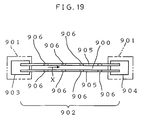
- FIG. 19 a schematic plan view of a conventional transfer is illustrated in Figure 19.
- the conventional transfer comprises frames 901 comprising a workpiece transfer path 900 extending in the X-direction, and a square movement mechanism 902 for intermittently transferring workpieces on the workpiece transfer path 900 in the X-direction.
- the square movement mechanism 902 comprises a driving mechanism 903 disposed at one end of the X-direction, i.e., at the beginning end of the workpiece transfer, a driven mechanism 904 disposed at the other end of the X-direction, i.e., at the terminating end of the workpiece transfer, and a beam-shaped synchronizing mechanism 905 for connecting and synchronizing the driving mechanisms 903 and 904.
- the driving mechanism 903 is provided with an X-direction driver.
- the beam-shaped synchronizing mechanism 905 is driven to perform a square movement along the X-direction in the upward and downward directions.
- the synchronizing mechanism 905 is provided with transfer claws 906 for holding workpieces.
- the synchronizing mechanism 905 When the synchronizing mechanism 905 is driven to perform the square movement mechanism in the upward and downward directions, the workpieces held by the transfer claws 906 is intermittently transferred on the workpiece transfer path 900 one after another in the X-direction by one (1) pitch. The workpieces thus transferred is processed at processing steps disposed at every one (1) pitch.
- the above-mentioned conventional transfer is provided with the square movement mechanism 902.
- the square movement mechanism 902 comprises the driving mechanism 903 disposed at one end of the X-direction, i.e., at the beginning end of the workpiece transfer, the driven mechanism 904 disposed at the other end of the X-direction, i.e, at the terminating end of the workpiece transfer, and the beam-shaped synchronizing mechanism 905 for synchronizing the driving and driven mechanisms 903 and 904.
- the synchronizing mechanism 905 is bridged in the X-direction, in which the workpieces are transferred one after another.
- the length of the workpiece transfer path 900 increases.
- the beam-shaped synchronizing mechanism 905 should be made longer, and it is required to highly strengthen and rigidify the beam-shaped synchronizing mechanism 905 in order to prevent the beam-shaped synchronizing mechanism 905 from bending.
- the weight and inertia force of the beam-shaped synchronizing mechanism 905 increase. Therefore, in the above-mentioned conventional transfer, the inertia force thereof, exerted by the square movement of the beam-shaped synchronizing mechanism 905, tends to increase when the number of workpiece processing steps increases.
- each of the rough forging die, the finish forging die and the deflashing die is made integral. Consequently, it is not always easy to take out the products from the cavities of the dies, depending on the cavity configurations, volumes and the like of the dies.
- the preamble of the claim 1 however starts out from a bolster apparatus as is shown in the GB 1 250 117. From this reference, it is known to mount pressing tools and transfer mechanisms for carrying workpieces to and from a movable bolster, so that, when the product is changed, the transfer mechanism as well as the corresponding pressing tool can be exchanged in one operation.
- the gist of the invention is that a first driver and a second driver which drive a plurality of claws are held within the bolster. Accordingly, the drivers accomodated in the respective bolster do not work as a driving source for the pressing apparatus.
- the present invention adopts the “Driving Source-Separate System", wherein the claws driving source is provided as a separate system from the driving source for the pressing apparatus. Therefore, in the present invention, the claws are controlled independently from the driving of the pressing apparatus. Namely, the present invention adopts "Claws-Independent System”.
- the workpiece is pressing-formed and then the transfer claws start driving, when the mechanism in a pressing apparatus drives. That is, in the GB-document, the mechanism works as the driving source for the pressing apparatus and the driving source for the transfer claws, as well. In short, this document adopts the "Driving Source-Common Use System".
- the bolster main body has the mounting portions to be mounted to the bolster mounting portion of the pressing apparatus.
- the structure of the bolster mounting portion may be determined as the occasion may demand.
- the following are representatives of the pressing apparatus: a forging press apparatus, a sheet metal pressing apparatus and the like.
- the die holding portion of the bolster main body has a structure for holding dies for press-forming workpieces.
- the structure may comprise die holding bores. Tile first die, the second die and the third die are at least held by the die holding portion of the bolster main body.
- first, second and third dies forging dies, sheet metal pressing dies, punching dies, drawing dies and the like may be employed depending on the type of the press-formings.
- forging dies as described in the section of "DESCRIPTION OF THE PREFERRED EMBODIMENT OF THE INVENTION"
- the following dies are representatives of the first, second and third dies respectively: a rough forging die, a finish forging die and a deflashing die.
- the bolster main body further comprises a set of transfer claws disposed in a manner capable of performing the square movement in the two-dimensional direction or three-dimensional direction, and the square movement mechanism for operating the square movement of the set of the transfer claws in the two-dimensional direction or the three-dimensional direction.
- the square movement means a movement comprising a movement for advancing and retracting the set of transfer claws in the two-dimensional direction or the three-dimensional direction and a movement for opening and closing the set of transfer claws in the two-dimensional direction or the three-dimensional direction.
- the set of transfer claws comprises the pair of the first transfer claws, the pair of the second transfer claws and the pair of the third transfer claws at least. Configurations of the set of the transfer claws may be determined depending on the occasion, for instance, they may be a finger shape, a grip shape and the like.
- the operation of the bolster apparatus according to this invention will be hereinafter described along with its usage.
- the mounting portion of the bolster main body is first mounted to the bolster mounting portion of the pressing apparatus.
- the pressing apparatus with the bolster apparatus mounted is operated, a workpiece is pressed by the first die.
- the first transfer claws are operated by the operation of the square movement mechanism held in the bolster main body, thereby transferring the workpiece pressed by the first die to the second die.
- the workpiece pressed by the first die is pressed by the second die.
- the second transfer claws are operated by the operation of the square movement mechanism, thereby transferring the workpiece pressed by the second die to the third die.
- the third transfer claws are operated by the operation of the square movement mechanism, thereby transferring the workpiece pressed by the third die to the other location.
- the bolster apparatus for press-forming workpieces according to this invention is advantageous not only for improving productivity but also for producing various types of products by the small lot, because the transfer can be exchanged simultaneously with the exchange of the bolster apparatuses.
- the bolster apparatus according to this invention has enabled the above-mentioned process for press-forming workpieces.
- the bolster apparatus according this invention has done away with the base for the transfer, because the square movement mechanism constituting the transfer is incorporated in the bolster main body.
- the arrangement of the bolster apparatus according to this invention is advantageous for reducing the inertia force thereof, because the weight of the transfer thereof can be kept substantially the same even when the number of workpiece processing steps increases.
- the bolster apparatus in the bolster apparatus according to this invention, at last one of the dies can be made separable and movable in a manner interlocking with the movement of the transfer.
- the bolster apparatus according to this invention enables to easily take-out the, workpieces from the dies.
- the bolster main body 1 is integrally composed of a driving bolster member 10 mounted to a bolster mounting portion "A100" of a forging press apparatus "A", a driven bolster apparatus 14 also mounted to the bolster mounting portion "A100” of the forging press apparatus “A”, and a die holding portion 17 disposed between the driving bolster member 10 and the driven bolster member 14.
- the driving bolster member 10 is provided with mounting bores 10a constituting a mounting portion, and mounted detachably to the mounting portion "A100" of the forging press apparatus "A” by bolts inserted into the mounting bores 10a.
- the driven bolster member 14 is mounted to the mounting portion "A100" of the forging press apparatus "A” in a similar manner.
- the driving bolster member 10 will be hereinafter described.
- the driving bolster member 10 comprises a front frame 100, main stays 101, sub-stays 102, side frames 104 fixed between the main stays 101 and sub-stays 102 by bolts 103, and a bearing case 105 fixed on the front frame 100.
- the side frames 104 are provided with a reinforcement pin 106 for reinforcing themselves.
- the driven bolster member 14 comprises a front frame 140, main stays 141, sub-stays 142, side frames 144 fixed between the main stays 141 and sub-stays 142 by bolts, and a bearing case 145 fixed on the front frame 140.
- the side frames 144 are provided with a reinforcement pin 146 for reinforcing themselves.
- a workpiece transfer path 17a of the die holding portion 17 has die holding bores 170, 171, 172 and 173 disposed in series.
- a crushing lower half die 174, a rough forging lower half die 175 as a first die, a finish forging lower half die 176 as a second die and a deflashing lower half die 177 as a third die are inserted into and held in the die holding bores 170, 171, 172 and 173, respectively.
- the bolster main body 1 comprises a set of driving transfer claws 2 and a set of driven transfer claws 3 constituting a set of transfer claw.
- the set of driving transfer claws 2 comprises a driving mounting plate 20 and a transfer claw 21, a first transfer claw 22, a second transfer claw 23 and a sweeper 24 as a third transfer claw, all of which are disposed on the driving mounting plate 20.
- the set of driven transfer claws 3 comprises a driven mounting plate 30 and a transfer claw 31, a first transfer claw 32, a second transfer claw 33 and a sweeper 34 as a third transfer claw, all of which are disposed on the driven mounting plate 30.
- FIG. 5 and 6 the first transfer claws 2 and 3 will be hereinafter described.
- bushes 25 and 35 are inserted into holes 22a and 32a of the first transfer claws 2 and 3 respectively.
- Bolts 26 and 36 are inserted into the bushes 25 and 35, and screwed in threaded holes 22b and 32b of the mounting plates 20 and 30 respectively.
- springs 27 and 37 for effecting workpiece gripping operation are interposed between the first transfer claws 22 and the mounting plate 20 and between the first transfer claw 32 and the mounting plate 30 respectively.
- the transfer claws 21 and 31 as well as the second transfer claws 23 and 33 have an identical construction.
- the bolster main body 1 is provided with a square movement mechanism 4 for actuating the horizontal two-dimensional square movement of the set of driving transfer claws 2 and the set of driven transfer claws 3 and effecting transfer operation.
- the square movement mechanism 4 will be hereinafter described.
- the square movement mechanism 4 comprises a driving mechanism 5 disposed in the driving bolster member 10, a driven mechanism 6 disposed in the driven bolster member 14 and a synchronizing mechanism 7, illustrated in Figure 15, for synchronously transmitting the movement of the driving mechanism 5 to the driven mechanism 6.
- the driving mechanism 5 will be described with reference to Figures 7 through 11.
- the right and left direction of the drawing is taken as the X-direction
- the top and bottom direction is taken as the Y-direction.
- a feed shaft 50 is fixed between the side frames 104 at the right and the side frames 104 at the left by bolts 51.
- a movable feed shaft 52 is held in the side frame 104 at the right by a bearing 520 and a bearing 107 in the bearing case 105, and movable in the axial direction thereof, i.e., the directions of the arrows "X1" and "X2" in Figure 7.
- a movable stand 522 is fixed to the movable feed shaft 52 at the end by a bolt 521.
- the movable stand 522 engages with the set of driving transfer claws 2 and the set of driven transfer claws 3, and moves the set of driving transfer claws 2 and the set of driven transfer claws 3 in the directions of the arrows "X1" and "X2".
- a pneumatic cylinder 53 for advancing and retracting the movable feed shaft 52 is fixed on the front frame 100 of the driving bolster member 10 by fixtures 53a.
- a cylinder rod 530 of the pneumatic cylinder 53 is connected to a motion mixer 54 by a bolt 531a while being interposed by a connector 531, and the motion mixer 54 is connected to the movable feed shaft 52 by a fixture 54a.
- An absorber stopper 55 is further connected to the motion mixer 54.
- the absorber stopper 55 is held movably by the feed shaft 50 while being interposed by a bearing 550.
- the cylinder rod 530 of the pneumatic cylinder 53 is actuated either in the direction of the arrow "X1" or in the direction of the arrow "X2"
- the movable feed shaft 52, the movable stand 522, the motion mixer 54 and the absorber stopper 55 are moved in the same direction.
- An absorber 56 is further provided for absorbing shocks when the absorber stopper 55 bumps into it.
- guide shafts 57 are fixed parallel to the Y-direction in the side frames 104 by bolts 57a.
- Two (2) transfer shafts 58 are connected to the guide shafts 57 by way of bearings 580 and transfer shaft holders 581 in a manner extending in the direction of X-direction and bridging the guide shafts 57 at the right and left. Because the bearings 580 are guided along the guide shafts 57, the transfer shafts 58 are movable in the length direction of the guide shafts 57, i.e., in the Y-direction.
- a pneumatic cylinder 59 for opening and closing i.e., a driver for effecting the movements in the Y-direction
- the pneumatic cylinder 59 is incorporated into the bolster main body 1 in addition to the pneumatic cylinder 53, because this preferred embodiment features the square movement mechanism 4 incorporated into the bolser main body 1.
- This arrangement is advantageous for downsizing the overall apparatus when compared with a bolster main body 1 into which a motor mechanism is incorporated.
- a cylinder rod 590 of the pneumatic cylinder 59 is connected to a link driving shaft 592 by a bolt 591a while being interposed by a connector 591.
- the link driving shaft 592 is inserted into a holding bore 540 of the motion mixer 54, and the motion mixer 54 is held substantially at the center of the link driving shaft 592.
- two (2) shafts 541 are disposed in the motion mixer 54 in a manner extending in the Y-direction.
- a movable member 543 is held by the shafts 541 while being interposed by bearings 543d.
- a transfer base 544 is further fixed to the movable member 543 by a bolt 543a and a nut 543b.
- the mounting plate 20 of the set of driving transfer claws 2 are fixed to the transfer base 544 by bolts assembled in mounting holes 544a of the transfer base 544. Because bearings 544b of the transfer base 544 is slidable along the transfer shafts 58, the transfer base 544 is movable along the transfer shafts 58 in the X-direction.
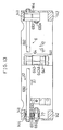
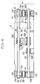
- the driven mechanism 6 of the square movement mechanism 4 will be hereinafter described with reference to Figures 12 through 14.
- the driven mechanism 6 is disposed in the driven bolster member 14, and has an mechanism basically identical with that of the above-mentioned driving mechanism 5 disposed in the driving bolster member 10.
- the driven mechanism 6 differs from the driving mechanism 5 in that no pneumatic cylinder 53 for advancing and retracting and pneumatic cylinder 59 constituting the drivers are provided in the driven mechanism 6.
- a feed shaft 60 is fixed between the side frames 144 at the right and the side frames 144 at the left by bolts 61. Further, a movable feed shaft 62 is held in the side frames 144 at the right by a bearing 620 and a bearing 147 in the bearing case 145, and movable in the axial direction thereof, i.e., the directions of the arrows "X1" and "X2" in Figure 14.
- a motion mixer 64 is fixed to the movable feed shaft 62 while being interposed by a connector 631. The end of the movable feed shaft 62 is connected to the above-mentioned movable stand 522.
- guide shafts 67 are fixed parallel to the Y-direction in the side frames 144.
- Two (2) transfer shafts 68 are connected to the guide shafts 67 by way of bearings 680 and transfer shaft holders 681 in a manner extending in the direction of X-direction and bridging the guide shafts 67 at the right and left.
- the transfer shafts 68 are movable in the length direction of the guide shafts 67, i.e., in the Y-direction.
- a link driving shaft 692 is inserted into a holding bore of the motion mixer 64, and the motion mixer 64 is held substantially at the center of the link driving shaft 692. When the link driving shaft 692 is moved either in the direction of the arrow "Y1" or in the direction of the arrow "Y2", the motion mixer 64 can be moved accordingly.
- the synchronizing mechanism 7 for synchronizing the driving mechanism 5 with the driven mechanism 6 will be hereinafter described.
- two (2) synchronizing mechanisms 7 are disposed in the bolster main body 1 at the right and left ends of the X-direction thereof for securing synchronizing performance.
- the synchronizing mechanisms 7 comprise link pins 70 and 71 rotatably engaging with the side frames 104, link plates 72 swingably held by the link pins 70 and 71, and link plates 74 swingably held by the link pins 71 and the link driving shaft 592.
- the synchronizing mechanisms 7 further comprise link plates 77 held swingably by link pins 76 at the center thereof and held by link pins 692a at one end thereof, link plates 693 connecting the link pins 692a and the link driving shaft 692, and synchronizing shafts 78 connecting the driving link plates 72 and the driven link plates 77 by pins 78a and 78b.
- reference numbers 70a's, 71a's and 592a's specify bearings.
- a die mounting member 80 is held by the mounting plate 20 of the set of driving transfer claws 2 and the mounting plate 30 of the set of driven transfer claws 3, and a clamping die 81 is fixed to the die mounting member 80.
- a clamping surface 82 for clamping a finish forged product W3 one of workpieces is formed on the the clamping die 81 in a semicircular arc shape.
- a guide bore 177a is formed on the deflashing lower half die 177, and the clamping die 81 is slidable on the wall surface of the guide bore 177a in the direction of the arrow "T".
- the forging press apparatus "A” to which the above-mentioned bolster apparatus of this preferred embodiment is mounted will be described with reference to Figure 18.
- the forging press apparatus “A” comprises a lower member provided with a knock-out piston 800, knock-out pins 801 and 802, and an upper member provided with a knock-out plate 820, knock-out pins 821, 822, 823 and 824, and a chute 825.
- an upper bolster apparatus 184 is further provided in which a crushing upper half die 184, a rough forging upper half die 185, a finish forging upper half die 186 and a deflashing upper half die 187 are attached.
- the bolster apparatus of this preferred embodiment described above are operated as follows. First, the forging press apparatus "A" is actuated with the following set-up as shown in Figure 18: a workpiece W0 is placed in the crushing lower half die 174, a crushed workpiece W1 which has been crushed and deformed by the crushing lower half die 174 and the crushing upper half die 184 is placed in the rough forging lower half die 175, and a rough forged product W3 which has been molded by the rough forging lower half die 175 and the rough forging upper half die 185 is placed in the finish forging lower half die 176.
- the workpiece W0 is crushed by the crushing lower half die 174 and the crushing upper half die 184
- the crushed workpiece W1 is rough-forged to a rough forged product W2 by tile rough forging lower half die 175 and the rough forging upper half die 185
- the rough forged product W2 - is finish-forged to a finish forged product W3 by the finish forging lower half die 176 and the finish forging upper half die 186
- the finish forged product W3 is deflashed by the deflashing lower half die 177 and the deflashing upper half die 187.
- the cylinder rod 590 of the pneumatic cylinder 59 of the square movement mechanism 4 for opening and closing, i.e., the Y-direction transfer operates in the direction of the arrow "Y1" to move the link driving shaft 592, the motion mixer 54 and the movable member 543 in the direction of the arrow "Y1" as shown in Figure 8.
- the set of driving transfer claws 2 is moved in the direction of the arrow "Y1" as shown in Figure 11.
- the cylinder rod 530 of the pneumatic cylinder 53 for advancing and retracting, i.e., the X-direction transfer operates to move the motion mixer 54 at the position specified by the alternate long and two dashes lines in Figure 7.
- the transfer base 544 accordingly advances in the direction of the arrow "X1"
- the movable stand 522 fixed at the end of the movable feed shaft 552 advances in the same direction .
- the set of driving transfer claws 2 and the set of driven transfer claws 3 engaging with the movable stand 522 by way of the mounting plates 20 and 30 are advanced in the direction of the arrow "X1".
- the pneumatic cylinder 59 for opening and closing therefor actuate to extend the cylinder rod 590 in the direction of the arrow "Y2" as shown in Figure 8.
- the link driving shaft 592 and the motion mixer 54 move in the direction of the arrow "Y2".
- the link driving shaft 592 moves in the direction of the arrow "Y2” and the transfer base 544 moves in the same direction therewith, the set of the driving transfer claws 2 is opened consequently.
- the transfer claws 21 and 31 release the crushed workpiece W1
- the first transfer claws 22 and 32 release the rough forged product W2
- the second transfer claws 23 and 33 release the finish forged product W3.
- the crushed workpiece W1, the rough forged product W2 and the finish forged product W3 are advanced by a predetermined pitch, i.e., the stroke-length of the pneumatic cylinder 53 for the X-direction transfer, and transferred to the subsequent processing positions.
- the forging press apparatus "A” actuates to move the crushing upper half die 184, the rough forging upper half die 185, the finish forging upper half die 186 and the deflashing upper half die 187 downward. Accordingly, the crushed workpiece W1 is rough-forged to a rough forged product W2, the rough forged product W2 is finish-forged to a finish forged product W3, and the finish forged product W3 is deflashed.
- the clamping surface 82 of the clamping die 81 is away from the deflashing lower half die 177 when the set of driving transfer claws 2 and the set of driven transfer claws 3 are moving in the direction of the arrow "X1".
- the finish forged product W3 are held and transferred by the second transfer claw 23 of the set of driving transfer claws 2 and the second transfer claws 33 of the set of driven transfer claws 3, and placed in the cavity of the deflashing lower half die 177.
- the deflashing upper half die, 187 is moved downward to deflash the central bore W30 of the finish forged product W3.
- the sweepers 24 and 34 put into the closing state are advanced in the direction of the arrow "X1", thereby discharging the deflashed finish forged product W3 out to the chute 825 through a guide bore 177a.
- square movement mechanism 4 can be exchanged automatically by exchanging the bolster main bodies 1.
- the forging press "A" is operated to perform another series of press forming processes to forge and produce the another product.
- the process for press-forming workpieces according to this preferred embodiment is advantageous when producing various products by the small lot, because the square mechanisms 4 constituting transfers can be exchanged automatically by exchanging the bolster apparatuses. It is also understood that the bolster apparatus according to this preferred embodiment has enabled the above-mentioned process for pressing workpieces.
- the driving mechanism 903 of the square movement mechanism 902 is disposed at one end of the workpiece advancement direction, i.e., at one end of the X-direction, and that the driven mechanism 904 of the square movement mechanism 902 is disposed at the other end of the workpiece advancement direction.
- the length of rods 905 connecting the driving mechanism 903 and the driven mechanism 904 increases, and that the inertia masses arid inertia forces thereof tend to increase in accordance with the increasing rod 905 length. Consequently, the structures of the rods 905 and the bolster apparatus should be highly strengthened and rigidified.
- this preferred embodiment has the driving mechanism 5 disposed at one end of the Y-direction which intersects the workpiece W transfer direction (the X-direction), and the driven mechanism 6 disposed at the other end of the Y-direction.
- the driving mechanism 5 disposed at one end of the Y-direction which intersects the workpiece W transfer direction (the X-direction)
- the driven mechanism 6 disposed at the other end of the Y-direction.
- the above-mentioned preferred embodiment is an example applied to a forging press process, but can be applied to a sheet metal press process, a deep drawing process and so on. Further, the bolster apparatus according to this invention is not limited to the preferred embodiment described above and illustrated in the drawings.
Landscapes
- Engineering & Computer Science (AREA)
- Mechanical Engineering (AREA)
- Forging (AREA)
- Mounting, Exchange, And Manufacturing Of Dies (AREA)
Description
- This invention relates to a bolster apparatus for press-forming workpieces according to the preamble of claim 1. In particular, this invention relates to a bolster apparatus, in which the workpieces are transferred and press-formed one after another.
- When performing a forgoing press process, a bolster is mounted to a bolster mounting portion of a forging press apparatus, a rough forging die, a finish forging die and a deflashing die are then disposed in series in die holding bores of the bolster, and a transfer is further provided to the forging press apparatus independently of the bolster. In this conventional arrangement, the forging press apparatus and the transfer are operated. Rough forged products are produced by the rough forging die from a blank material, the rough forged products produced are transferred to the finish forging die by the transfer, finish forged products are then produced by the finish forging die from the rough forged products, the finish forged products produced are transferred to the deflashing die by the transfer, and the finish forged products are finally deflashed by the deflashing die.
- In the above-mentioned forging press process, a base exclusively for the transfer should be provided on the floor because the transfer is provided to the forging press apparatus independently of the bolster. In addition, when changing production set-ups from a product to the other product, not only the rough forging die, the finish forging die and the deflashing die but also the bolster for holding these dies should be exchanged. Further, when a production set-up has been changed and the workpiece transfer pitch has been varied, the transfer should be exchanged in addition to the above-mentioned exchanges of the forging dies and bolster. It is therefore disadvantageous in view of productivity because a process for exchanging the transfer is required as well as a process for exchanging the forging dies and the bolster.
- In order to overcome the above-mentioned drawbacks, a transfer adapted to the multi-function or the multi-purpose application should be employed to make the workpieces transferable with an identical transfer even when the production set-ups have been changed. Consequently, the mechanism and function of the transfer get complicated, and the cost thereof becomes expensive remarkably.
- For example, a schematic plan view of a conventional transfer is illustrated in Figure 19. As shown in Figure 19, the conventional transfer comprises
frames 901 comprising aworkpiece transfer path 900 extending in the X-direction, and asquare movement mechanism 902 for intermittently transferring workpieces on theworkpiece transfer path 900 in the X-direction. - The
square movement mechanism 902 comprises adriving mechanism 903 disposed at one end of the X-direction, i.e., at the beginning end of the workpiece transfer, a drivenmechanism 904 disposed at the other end of the X-direction, i.e., at the terminating end of the workpiece transfer, and a beam-shaped synchronizing mechanism 905 for connecting and synchronizing thedriving mechanisms driving mechanism 903 is provided with an X-direction driver. The beam-shaped synchronizing mechanism 905 is driven to perform a square movement along the X-direction in the upward and downward directions. The synchronizingmechanism 905 is provided withtransfer claws 906 for holding workpieces. When the synchronizingmechanism 905 is driven to perform the square movement mechanism in the upward and downward directions, the workpieces held by thetransfer claws 906 is intermittently transferred on theworkpiece transfer path 900 one after another in the X-direction by one (1) pitch. The workpieces thus transferred is processed at processing steps disposed at every one (1) pitch. - The above-mentioned conventional transfer is provided with the
square movement mechanism 902. Thesquare movement mechanism 902 comprises thedriving mechanism 903 disposed at one end of the X-direction, i.e., at the beginning end of the workpiece transfer, the drivenmechanism 904 disposed at the other end of the X-direction, i.e, at the terminating end of the workpiece transfer, and the beam-shaped synchronizing mechanism 905 for synchronizing the driving and drivenmechanisms square movement mechanism 902, the synchronizingmechanism 905 is bridged in the X-direction, in which the workpieces are transferred one after another. When the number of workpiece processing steps increases, the length of theworkpiece transfer path 900 increases. Accordingly, the beam-shaped synchronizing mechanism 905 should be made longer, and it is required to highly strengthen and rigidify the beam-shaped synchronizing mechanism 905 in order to prevent the beam-shaped synchronizing mechanism 905 from bending. As a result, the weight and inertia force of the beam-shaped synchronizing mechanism 905 increase. Therefore, in the above-mentioned conventional transfer, the inertia force thereof, exerted by the square movement of the beam-shaped synchronizing mechanism 905, tends to increase when the number of workpiece processing steps increases. - Further, in the above-mentioned forging press apparatus, each of the rough forging die, the finish forging die and the deflashing die is made integral. Consequently, it is not always easy to take out the products from the cavities of the dies, depending on the cavity configurations, volumes and the like of the dies.
- The preamble of the claim 1 however starts out from a bolster apparatus as is shown in the GB 1 250 117. From this reference, it is known to mount pressing tools and transfer mechanisms for carrying workpieces to and from a movable bolster, so that, when the product is changed, the transfer mechanism as well as the corresponding pressing tool can be exchanged in one operation.
- However, it is an object of the present invention to provide a bolster apparatus of that kind, which makes it possible to increase the productivity of a process for pressforming workpieces.
- According to the invention this object is achieved by the features indicated in the main claim.
- Accordingly, the gist of the invention is that a first driver and a second driver which drive a plurality of claws are held within the bolster. Accordingly, the drivers accomodated in the respective bolster do not work as a driving source for the pressing apparatus.
- In other words, the present invention adopts the "Driving Source-Separate System", wherein the claws driving source is provided as a separate system from the driving source for the pressing apparatus. Therefore, in the present invention, the claws are controlled independently from the driving of the pressing apparatus. Namely, the present invention adopts "Claws-Independent System".
- In the present invention, wherein the "Claws-Independent System" is adopted, the following advantageous effects (A) to (C) can be obtained.
- (A): In a forging press apparatus, it is very important to determine the timing for setting a workpiece in a die and the timing for taking out the workpiece from the die. In the present invention, each timing can be selected freely because the claws can be controlled independently from the driving of the pressing apparatus.
- (B): In order to improve the productivity, it is preferable to conduct a trial operation of claws under the preparation state. In the present invention, the trial operation of the claws can be conducted if the first driver and the second driver are driven before mounting the bolster on the pressing apparatus, since the driving source for claws and the driving source for the pressing apparatus are provided separately.
- (C): When changing the type of the workpiece, claws transferring pitch in the workpiece transfer direction should be varied. In the present invention, when changing the type of the workpiece, the claws transferring pitch can be changed by removing the bolster from the pressing apparatus and exchanging for a new bolster.
- The essential features of the subject matter of the application are not known from the bolster apparatus according to the GB 1 250 117.
- In this reference, the workpiece is pressing-formed and then the transfer claws start driving, when the mechanism in a pressing apparatus drives. That is, in the GB-document, the mechanism works as the driving source for the pressing apparatus and the driving source for the transfer claws, as well. In short, this document adopts the "Driving Source-Common Use System".
- In the US-A-3707908, a shaft and a bevel gear in a press head of the pressing apparatus drive the transfer claws. Namely, in, the US-document as well as in, the GB-document the driving source for the transfer claws is the same with the one for the pressing apparatus. Also in the US-A-3707908, "Driving Source-Common Use System" is employed.
- The bolster apparatus according to this invention will now be hereinafter described. The bolster main body has the mounting portions to be mounted to the bolster mounting portion of the pressing apparatus. The structure of the bolster mounting portion may be determined as the occasion may demand. The following are representatives of the pressing apparatus: a forging press apparatus, a sheet metal pressing apparatus and the like. The die holding portion of the bolster main body has a structure for holding dies for press-forming workpieces. For instance, the structure may comprise die holding bores. Tile first die, the second die and the third die are at least held by the die holding portion of the bolster main body. For the first, second and third dies, forging dies, sheet metal pressing dies, punching dies, drawing dies and the like may be employed depending on the type of the press-formings. When employing the forging dies, as described in the section of "DESCRIPTION OF THE PREFERRED EMBODIMENT OF THE INVENTION", the following dies are representatives of the first, second and third dies respectively: a rough forging die, a finish forging die and a deflashing die.
- The bolster main body further comprises a set of transfer claws disposed in a manner capable of performing the square movement in the two-dimensional direction or three-dimensional direction, and the square movement mechanism for operating the square movement of the set of the transfer claws in the two-dimensional direction or the three-dimensional direction.
- Here, the square movement means a movement comprising a movement for advancing and retracting the set of transfer claws in the two-dimensional direction or the three-dimensional direction and a movement for opening and closing the set of transfer claws in the two-dimensional direction or the three-dimensional direction. The set of transfer claws comprises the pair of the first transfer claws, the pair of the second transfer claws and the pair of the third transfer claws at least. Configurations of the set of the transfer claws may be determined depending on the occasion, for instance, they may be a finger shape, a grip shape and the like.
- The operation of the bolster apparatus according to this invention will be hereinafter described along with its usage. The mounting portion of the bolster main body is first mounted to the bolster mounting portion of the pressing apparatus. When the pressing apparatus with the bolster apparatus mounted is operated, a workpiece is pressed by the first die. The first transfer claws are operated by the operation of the square movement mechanism held in the bolster main body, thereby transferring the workpiece pressed by the first die to the second die. Then, the workpiece pressed by the first die is pressed by the second die. Further, the second transfer claws are operated by the operation of the square movement mechanism, thereby transferring the workpiece pressed by the second die to the third die. Similarly, the third transfer claws are operated by the operation of the square movement mechanism, thereby transferring the workpiece pressed by the third die to the other location.
- It is thus apparent that the bolster apparatus for press-forming workpieces according to this invention is advantageous not only for improving productivity but also for producing various types of products by the small lot, because the transfer can be exchanged simultaneously with the exchange of the bolster apparatuses.
- The bolster apparatus according to this invention has enabled the above-mentioned process for press-forming workpieces. In addition, the bolster apparatus according this invention has done away with the base for the transfer, because the square movement mechanism constituting the transfer is incorporated in the bolster main body.
- Further, the arrangement of the bolster apparatus according to this invention is advantageous for reducing the inertia force thereof, because the weight of the transfer thereof can be kept substantially the same even when the number of workpiece processing steps increases.
- Furthermore, in the bolster apparatus according to this invention, at last one of the dies can be made separable and movable in a manner interlocking with the movement of the transfer. Thus, the bolster apparatus according to this invention enables to easily take-out the, workpieces from the dies.
-
- A more complete appreciation of the invention and many of the attendant advantages thereof will be readily obtained as the same becomes better understood by reference to the following detailed description when considered in connection with the accompanying drawings, wherein:
- Figure 1 is an overall perspective view of a preferred embodiment of a bolster apparatus according to this invention;
- Figure 2 is a schematic overall plan view of the preferred embodiment of the bolster apparatus according to this invention;
- Figure 3 is a plan view illustrating sets of transfer claws of the preferred embodiment of the bolster apparatus according to this invention;
- Figure 4 is a bottom view illustrating a set of a crushing upper half die, a rough forging upper half die, a finish forging upper half die and a deflashing upper half die of the preferred embodiment of the bolster apparatus according to this invention;
- Figures 5 and 6 illustrate first transfer claws of the preferred embodiment of the bolster apparatus according to this invention, wherein;
- Figure 5 is an enlarged plan view thereof; and
- Figure 6 is an enlarged cross-sectional view thereof;
- Figures 7 through 11 illustrate a driving bolster member and a driving mechanism of a square movement mechanism of the preferred embodiment of the bolster apparatus according to this invention, wherein;
- Figure 7 is a view taken in the direction of the arrows A-A of Figure 10;
- Figure 8 is a view taken in the direction of the arrows B-B of Figure 10;
- Figure 9 is a plan view of the driving mechanism with both of the top and bottom covers thereof removed and also a view taken in tile direction of tie arrows G-G of Figure 10;
- Figure 10 is a side view of the driving mechanism and also a view taken in the direction of arrows D-D of Figure 9; and
- Figure 11 is a view taken in the direction of the arrow E of Figure 8;
- Figures 12 through 14 illustrate a driven bolster member and a driven mechanism of a square movement mechanism of the preferred embodiment of the bolster apparatus according to this invention, wherein;
- Figure 12 is a plan view of the driven mechanism with both of the top and bottom covers thereof removed;
- Figure 13 is a plan view thereof and corresponds to Figure 8; and
- Figure 14 is a plan view thereof and corresponds to Figure 7;
- Figure 15 is a side view illustrating a synchronizing mechanism of the preferred embodiment of the bolster apparatus according to this invention;
- Figure 16 is a perspective view of a major portion of the preferred embodiment of the bolster apparatus according to this invention for deflashing operation;
- Figure 17 is also a perspective view of the major portion thereof for deflashing operation;
- Figure 18 is a cross-sectional view of the preferred embodiment of the bolster apparatus according to this invention incorporated into a forging press apparatus; and
- Figure 19 is a schematic plan view of a conventional transfer.
- Fig. 20 is a perspective view showing the important elements of the present invention.
- Having generally described this invention, a further understanding can be obtained by reference to certain specific preferred embodiment which is provided herein for purposes of illustration only and is not intended to be limiting unless otherwise specified.
- A representative preferred embodiment of a bolster apparatus according to this invention will be hereinafter described in detail with reference to the drawings. This preferred embodiment is an application of this invention to a forging press apparatus.
- A bolster main body 1, a major element of the bolster apparatus, will be first described. As shown in Figure 1, the bolster main body 1 is integrally composed of a driving bolster
member 10 mounted to a bolster mounting portion "A100" of a forging press apparatus "A", a driven bolsterapparatus 14 also mounted to the bolster mounting portion "A100" of the forging press apparatus "A", and adie holding portion 17 disposed between the driving bolstermember 10 and the driven bolstermember 14. Here, the driving bolstermember 10 is provided with mountingbores 10a constituting a mounting portion, and mounted detachably to the mounting portion "A100" of the forging press apparatus "A" by bolts inserted into the mountingbores 10a. The driven bolstermember 14 is mounted to the mounting portion "A100" of the forging press apparatus "A" in a similar manner. - With reference to Figures 7 through 11, the driving bolster
member 10 will be hereinafter described. As shown mainly in Figure 7, the driving bolstermember 10 comprises afront frame 100,main stays 101, sub-stays 102, side frames 104 fixed between the main stays 101 andsub-stays 102 bybolts 103, and abearing case 105 fixed on thefront frame 100. The side frames 104 are provided with areinforcement pin 106 for reinforcing themselves. - Next, with reference to Figures 12 through 14, the driven bolster
member 14 will be hereinafter described. As shown mainly in Figure 14, the driven bolstermember 14 comprises afront frame 140,main stays 141, sub-stays 142, side frames 144 fixed between the main stays 141 andsub-stays 142 by bolts, and abearing case 145 fixed on thefront frame 140. The side frames 144 are provided with areinforcement pin 146 for reinforcing themselves. - Then, with reference to Figures 1 through 3, the
die holding portion 17 of the bolster main body 1 will be hereinafter described. A workpiece transfer path 17a of thedie holding portion 17 has die holdingbores die holding bores - The bolster main body 1 comprises a set of driving
transfer claws 2 and a set of driventransfer claws 3 constituting a set of transfer claw. As shown in Figure 1, the set of drivingtransfer claws 2 comprises adriving mounting plate 20 and atransfer claw 21, afirst transfer claw 22, asecond transfer claw 23 and asweeper 24 as a third transfer claw, all of which are disposed on thedriving mounting plate 20. The set of driventransfer claws 3 comprises a driven mountingplate 30 and atransfer claw 31, afirst transfer claw 32, asecond transfer claw 33 and asweeper 34 as a third transfer claw, all of which are disposed on the driven mountingplate 30. - Turning now to Figures 5 and 6, the
first transfer claws bushes holes first transfer claws Bolts bushes holes plates first transfer claws 22 and the mountingplate 20 and between thefirst transfer claw 32 and the mountingplate 30 respectively. Thetransfer claws second transfer claws - The bolster main body 1 is provided with a
square movement mechanism 4 for actuating the horizontal two-dimensional square movement of the set of drivingtransfer claws 2 and the set of driventransfer claws 3 and effecting transfer operation. Thesquare movement mechanism 4 will be hereinafter described. As shown in Figure 1, thesquare movement mechanism 4 comprises adriving mechanism 5 disposed in the driving bolstermember 10, a drivenmechanism 6 disposed in the driven bolstermember 14 and asynchronizing mechanism 7, illustrated in Figure 15, for synchronously transmitting the movement of thedriving mechanism 5 to the drivenmechanism 6. - The
driving mechanism 5 will be described with reference to Figures 7 through 11. In Figures 7 through 11, the right and left direction of the drawing is taken as the X-direction, and the top and bottom direction is taken as the Y-direction. In thedriving mechanism 5 illustrated in Figure 7, afeed shaft 50 is fixed between the side frames 104 at the right and the side frames 104 at the left bybolts 51. Further, amovable feed shaft 52 is held in theside frame 104 at the right by abearing 520 and abearing 107 in thebearing case 105, and movable in the axial direction thereof, i.e., the directions of the arrows "X1" and "X2" in Figure 7. Amovable stand 522 is fixed to themovable feed shaft 52 at the end by abolt 521. Themovable stand 522 engages with the set of drivingtransfer claws 2 and the set of driventransfer claws 3, and moves the set of drivingtransfer claws 2 and the set of driventransfer claws 3 in the directions of the arrows "X1" and "X2". Apneumatic cylinder 53 for advancing and retracting themovable feed shaft 52 is fixed on thefront frame 100 of the driving bolstermember 10 byfixtures 53a. Acylinder rod 530 of thepneumatic cylinder 53 is connected to amotion mixer 54 by abolt 531a while being interposed by a connector 531, and themotion mixer 54 is connected to themovable feed shaft 52 by afixture 54a. An absorber stopper 55 is further connected to themotion mixer 54. The absorber stopper 55 is held movably by thefeed shaft 50 while being interposed by abearing 550. When thecylinder rod 530 of thepneumatic cylinder 53 is actuated either in the direction of the arrow "X1" or in the direction of the arrow "X2", themovable feed shaft 52, themovable stand 522, themotion mixer 54 and the absorber stopper 55 are moved in the same direction. Anabsorber 56 is further provided for absorbing shocks when the absorber stopper 55 bumps into it. - As shown in Figure 9, guide
shafts 57 are fixed parallel to the Y-direction in the side frames 104 bybolts 57a. Two (2)transfer shafts 58 are connected to theguide shafts 57 by way ofbearings 580 and transfershaft holders 581 in a manner extending in the direction of X-direction and bridging theguide shafts 57 at the right and left. Because thebearings 580 are guided along theguide shafts 57, thetransfer shafts 58 are movable in the length direction of theguide shafts 57, i.e., in the Y-direction. - Turning now to Figure 8, a
pneumatic cylinder 59 for opening and closing, i.e., a driver for effecting the movements in the Y-direction, is fixed on thefront frame 100 of the driving bolstermember 10. Thepneumatic cylinder 59 is incorporated into the bolster main body 1 in addition to thepneumatic cylinder 53, because this preferred embodiment features thesquare movement mechanism 4 incorporated into the bolser main body 1. This arrangement is advantageous for downsizing the overall apparatus when compared with a bolster main body 1 into which a motor mechanism is incorporated. - A
cylinder rod 590 of thepneumatic cylinder 59 is connected to alink driving shaft 592 by a bolt 591a while being interposed by aconnector 591. Thelink driving shaft 592 is inserted into a holdingbore 540 of themotion mixer 54, and themotion mixer 54 is held substantially at the center of thelink driving shaft 592. When thelink driving shaft 592 is moved either in the direction of the arrow "Y1" or in the direction of the arrow "Y2", themotion mixer 54 can be moved accordingly. - As shown in Figures 8 and 11, two (2)
shafts 541 are disposed in themotion mixer 54 in a manner extending in the Y-direction. Amovable member 543 is held by theshafts 541 while being interposed bybearings 543d. As shown in Figures 9 and 11, atransfer base 544 is further fixed to themovable member 543 by abolt 543a and anut 543b. The mountingplate 20 of the set of drivingtransfer claws 2 are fixed to thetransfer base 544 by bolts assembled in mountingholes 544a of thetransfer base 544. Becausebearings 544b of thetransfer base 544 is slidable along thetransfer shafts 58, thetransfer base 544 is movable along thetransfer shafts 58 in the X-direction. - Turning back to Figure 8, when the
cylinder rod 590 of thepneumatic cylinder 59 retracts in the direction of the arrow "Y1" in the drawing, thelink driving shaft 592 and themotion mixer 54 move in the direction of the arrow "Y1". - Because, when the
shaft 592 moves in the direction of the arrow "Y1", thelink plate 74 and thelink pin 71 shown in Figure 10 move in the direction of the arrow "Y1", and thelink plate 72 swings around thelink pin 70 to the direction of the arrow "P1". When thelink plate 74 moves to the direction of the arrow "Y1", thetransfer shaft holder 581 moves in the direction of the arrow "Y1" along theguide shaft 57 in Figure 9, because thetransfer shaft holder 581 is connected to thelink plate 74." - Whereby the set of driving
transfer claws 2 held to thetransfer base 544 moves in the direction of the arrow "Y1", namely in the direction closing thereof. At this moment, as readily understood from Figure 9, thebearings 580 are, guided along theguide shafts 57, thereby moving thetransfer shafts 58 and thetransfer base 544 along theguide shafts 57 in the direction of the arrow "Y1". - The driven
mechanism 6 of thesquare movement mechanism 4 will be hereinafter described with reference to Figures 12 through 14. The drivenmechanism 6 is disposed in the driven bolstermember 14, and has an mechanism basically identical with that of the above-mentioneddriving mechanism 5 disposed in the driving bolstermember 10. However, the drivenmechanism 6 differs from thedriving mechanism 5 in that nopneumatic cylinder 53 for advancing and retracting andpneumatic cylinder 59 constituting the drivers are provided in the drivenmechanism 6. - Hereinafter, the driven
mechanism 6 of thesquare mechanism 4 will be described in detail. As shown in Figure 14, afeed shaft 60 is fixed between the side frames 144 at the right and the side frames 144 at the left bybolts 61. Further, amovable feed shaft 62 is held in the side frames 144 at the right by abearing 620 and abearing 147 in thebearing case 145, and movable in the axial direction thereof, i.e., the directions of the arrows "X1" and "X2" in Figure 14. Amotion mixer 64 is fixed to themovable feed shaft 62 while being interposed by aconnector 631. The end of themovable feed shaft 62 is connected to the above-mentionedmovable stand 522. Consequently, when themovable feed shaft 52 of thedriving mechanism 5 moves in the X-direction to move themovable stand 522 in the X-direction, themovable shaft 62 moves synchronously. Further, as shown in Figure 13, two (2)shafts 641 are disposed in themotion mixer 64 in a manner extending in the Y-direction. Amovable member 643 is held by theshafts 641 while being interposed bybearings 643d. As shown in Figures 12, atransfer base 644 is further fixed to themovable member 643 by abolt 643a and anut 643b. The mountingplate 30 of the set of driventransfer claws 3 are fixed to thetransfer base 644 by bolts assembled in mountingholes 644a of thetransfer base 644. - Moreover, as shown in Figure 12,
guide shafts 67 are fixed parallel to the Y-direction in the side frames 144. Two (2)transfer shafts 68 are connected to theguide shafts 67 by way ofbearings 680 and transfershaft holders 681 in a manner extending in the direction of X-direction and bridging theguide shafts 67 at the right and left. Thetransfer shafts 68 are movable in the length direction of theguide shafts 67, i.e., in the Y-direction. Turning now to Figure 13, alink driving shaft 692 is inserted into a holding bore of themotion mixer 64, and themotion mixer 64 is held substantially at the center of thelink driving shaft 692. When thelink driving shaft 692 is moved either in the direction of the arrow "Y1" or in the direction of the arrow "Y2", themotion mixer 64 can be moved accordingly. - Next, the
synchronizing mechanism 7 for synchronizing thedriving mechanism 5 with the drivenmechanism 6 will be hereinafter described. As shown in Figure 8, two (2) synchronizingmechanisms 7 are disposed in the bolster main body 1 at the right and left ends of the X-direction thereof for securing synchronizing performance. In the driving bolstermember 10, as shown in Figures 7, 8 and 10, the synchronizingmechanisms 7 comprise link pins 70 and 71 rotatably engaging with the side frames 104,link plates 72 swingably held by the link pins 70 and 71, andlink plates 74 swingably held by the link pins 71 and thelink driving shaft 592. In the driven bolstermember 14, as shown in Figure 15, the synchronizingmechanisms 7 further compriselink plates 77 held swingably bylink pins 76 at the center thereof and held bylink pins 692a at one end thereof,link plates 693 connecting the link pins 692a and thelink driving shaft 692, and synchronizingshafts 78 connecting the drivinglink plates 72 and the drivenlink plates 77 bypins 78a and 78b. In Figures 7 through 10,reference numbers 70a's, 71a's and 592a's specify bearings. - As understood from Figure 8, when the
cylinder rod 590 of the above-mentionedpneumatic cylinder 59 moves in the direction of the arrow "Y1" to move thelink driving shaft 592 in the same direction, themixer 54 and themovable member 543 move in the direction of the arrow "Y1". Whereby the mountingplate 20 of the set of drivingtransfer claws 2, thetransfer claws sweeper 24 of the set of drivingtransfer claws 2 are moved in the direction of the arrow "Y1". Turning now to Figure 10, when thelink driving shaft 592 moves in the direction of the arrow "Y1", thelink plates 72 are pressed by way of thelink driving shaft 592, thelink plates 74 and thelink plates 71. Whereby thelink plates 72 swing around the link pins 70 in the direction of the arrow "P1" shown in Figure 10. Consequently, as shown in Figure 15, the synchronizingshafts 78 operate in the direction of the arrow "M1", and the link pins 77 of the drivenmechanism 6 accordingly swing in the direction of the arrow "N1". Whereby thelink driving shaft 692 is moved in the direction of the arrow "Y1" shown in Figure 15. As a result, the mountingplate 30 of the the set of driventransfer claws 3, thetransfer claws sweeper 34 of the set of driventransfer claws 3 are moved in the direction of the arrow "Y1". Thus, it is apparent from Figure 1 that the set of drivingtransfer claws 2 and the set of driventransfer claws 3 move in the closing direction when thepneumatic cylinder 59 operates. - In this preferred embodiment, as shown in Figure 3, a
die mounting member 80 is held by the mountingplate 20 of the set of drivingtransfer claws 2 and the mountingplate 30 of the set of driventransfer claws 3, and a clamping die 81 is fixed to thedie mounting member 80. As shown in Figures 3 and 16, a clampingsurface 82 for clamping a finish forged product W3, one of workpieces is formed on the the clamping die 81 in a semicircular arc shape. Further, aguide bore 177a is formed on the deflashing lower half die 177, and the clamping die 81 is slidable on the wall surface of theguide bore 177a in the direction of the arrow "T". - Lastly, the forging press apparatus "A" to which the above-mentioned bolster apparatus of this preferred embodiment is mounted will be described with reference to Figure 18. As shown in Figure 18, the forging press apparatus "A" comprises a lower member provided with a knock-
out piston 800, knock-outpins out plate 820, knock-outpins chute 825. As shown in Figure 4, in the forging press apparatus "A" to which the bolster apparatus of this preferred embodiment is mounted, an upper bolsterapparatus 184 is further provided in which a crushing upper half die 184, a rough forging upper half die 185, a finish forging upper half die 186 and a deflashing upper half die 187 are attached. - The bolster apparatus of this preferred embodiment described above are operated as follows. First, the forging press apparatus "A" is actuated with the following set-up as shown in Figure 18: a workpiece W0 is placed in the crushing lower half die 174, a crushed workpiece W1 which has been crushed and deformed by the crushing lower half die 174 and the crushing upper half die 184 is placed in the rough forging lower half die 175, and a rough forged product W3 which has been molded by the rough forging lower half die 175 and the rough forging upper half die 185 is placed in the finish forging lower half die 176. Accordingly, the workpiece W0 is crushed by the crushing lower half die 174 and the crushing upper half die 184, the crushed workpiece W1 is rough-forged to a rough forged product W2 by tile rough forging lower half die 175 and the rough forging upper half die 185, the rough forged product W2 -is finish-forged to a finish forged product W3 by the finish forging lower half die 176 and the finish forging upper half die 186, and the finish forged product W3 is deflashed by the deflashing lower half die 177 and the deflashing upper half die 187.
- When the crushing upper half die 184, the rough forging upper half die 185, the finish forging upper half die 186 and the deflashing upper half die 186 move upward, the
cylinder rod 590 of thepneumatic cylinder 59 of thesquare movement mechanism 4 for opening and closing, i.e., the Y-direction transfer, operates in the direction of the arrow "Y1" to move thelink driving shaft 592, themotion mixer 54 and themovable member 543 in the direction of the arrow "Y1" as shown in Figure 8. Whereby the set of drivingtransfer claws 2 is moved in the direction of the arrow "Y1" as shown in Figure 11. At this moment, the link pins 71 and thelink plates 74 move in the direction of the arrow "Y1" as shown in Figure 10 in accordance with the movement of thelink driving shaft 592 in the arrow "Y1". Thelink plates 72 swing around the link pins 70 in the direction of the arrow "P1" as shown in Figure 10. As a result, as shown in Figure 15, the synchronizingshafts 78 move in the direction of the arrow "M1", thelink plates 77 swing around the link pins 76 in the direction of the arrow "N1", and the driven link pins 692a and thelink driving shaft 692 move in the direction of the arrow "Y1" (see Figure 13.). Whereby the set of driventransfer claws 3 is moved in the direction of the arrow "Y1" (see Figure 1.). Thus, the set of drivingtransfer claws 2 and the set of driventransfer claws 3 close. Whereby thetransfer claws first transfer claws second transfer claws - While holding the workpieces W1 through W3, the
cylinder rod 530 of thepneumatic cylinder 53 for advancing and retracting, i.e., the X-direction transfer, operates to move themotion mixer 54 at the position specified by the alternate long and two dashes lines in Figure 7. Thetransfer base 544 accordingly advances in the direction of the arrow "X1", and themovable stand 522 fixed at the end of the movable feed shaft 552 advances in the same direction . Whereby the set of drivingtransfer claws 2 and the set of driventransfer claws 3 engaging with themovable stand 522 by way of the mountingplates transfer claws 2 and the set of driventransfer claws 3 reach the advance-end thereof, thepneumatic cylinder 59 for opening and closing therefor actuate to extend thecylinder rod 590 in the direction of the arrow "Y2" as shown in Figure 8. Thelink driving shaft 592 and themotion mixer 54 move in the direction of the arrow "Y2". When thelink driving shaft 592 moves in the direction of the arrow "Y2" and thetransfer base 544 moves in the same direction therewith, the set of the drivingtransfer claws 2 is opened consequently. - Further, when the
link driving shaft 592 moves in the direction of the arrow "Y2", as can be readily understood from Figure 10, thelink plates 74 and link pins 71, shown in Figure 10, move in the direction of the arrow "Y2" to swing thelink plates 72 around the link pins 70 in the direction of the arrow "P2". As a result, as shown in Figure 15, the synchronizingshafts 78 operate in the direction of the arrow "M2" to swing the drivenlink plates 77 around the link pins 76 in the direction of the arrow "N2". Thelink driving shaft 692 in the driven bolstermember 14 consequently moves in the direction of the arrow "Y2" shown in Figure 15. Whereby the set of the driventransfer claws 3 is opened in the direction of the arrow "Y2". Thus, the set of the drivingtransfer claws 2 and the set of the driventransfer claws 3 are opened. - In the above-mentioned manner, the
transfer claws first transfer claws second transfer claws pneumatic cylinder 53 for the X-direction transfer, and transferred to the subsequent processing positions. - When the workpieces W1 through W3 are thus advanced, the forging press apparatus "A" actuates to move the crushing upper half die 184, the rough forging upper half die 185, the finish forging upper half die 186 and the deflashing upper half die 187 downward. Accordingly, the crushed workpiece W1 is rough-forged to a rough forged product W2, the rough forged product W2 is finish-forged to a finish forged product W3, and the finish forged product W3 is deflashed.
- In the deflashing performance, as shown in Figure 16, the clamping
surface 82 of the clamping die 81 is away from the deflashing lower half die 177 when the set of drivingtransfer claws 2 and the set of driventransfer claws 3 are moving in the direction of the arrow "X1". In this situation, the finish forged product W3 are held and transferred by thesecond transfer claw 23 of the set of drivingtransfer claws 2 and thesecond transfer claws 33 of the set of driventransfer claws 3, and placed in the cavity of the deflashing lower half die 177. Thereafter the set of drivingtransfer claws 2 and the set of driventransfer claws 3 are retracted in the direction of the arrow "X2", the clamping die 81, interlocking with the set of drivingtransfer claws 2 and the set of driventransfer claws 3, is moved accordingly in the direction of the arrow "T" shown in Figure 16. Whereby the clampingsurface 82 of the clamping die 81 is brought into contact with the peripheral wall surface of the finish forged product W3. As shown in Figure 17, the finish forged product W3 is thus clamped by the clampingsurface 82 of the clamping die 81 and the cavity surface of the deflashing lower half die 177. While holding the finish forged product W3 in this manner, the deflashing upper half die, 187 is moved downward to deflash the central bore W30 of the finish forged product W3. After deflashing, thesweepers chute 825 through aguide bore 177a. - By the way, many workpieces should be processed when producing various products by the small lot. Accordingly, various bolster main bodies 1 exclusively for the various products are prepared depending on the types of workpieces. When changing a production set-up for a product to the other production set-ups for the other products, as shown in Figure 1, the bolts inserted into the the mounting bores 10a are first removed, and a bolster main body 1 is detached from the bolster mounting portion "A100" of the forging press apparatus "A". Then, the
driving mechanism 5 and the drivenmechanism 6 of thesquare movement mechanism 4 constituting the transfer are also detached automatically. Next, another driving bolstermember 10 and driven bolstermember 14 exclusively for another product are mounted to the bolster mounting portion "A100" of the forging press apparatus "A". Then, anotherdriving mechanism 5 and the drivenmechanism 6, constituting anothersquare mechanism 4 and being exclusively for another product, are attached automatically. Thus,square movement mechanism 4 can be exchanged automatically by exchanging the bolster main bodies 1. After the exchanging, the forging press "A" is operated to perform another series of press forming processes to forge and produce the another product. - It is understood from the above description that the process for press-forming workpieces according to this preferred embodiment is advantageous when producing various products by the small lot, because the
square mechanisms 4 constituting transfers can be exchanged automatically by exchanging the bolster apparatuses. It is also understood that the bolster apparatus according to this preferred embodiment has enabled the above-mentioned process for pressing workpieces. - On the other hand, in the conventional transfer mechanisms illustrated in Figure 19, it is a usual arrangement that the
driving mechanism 903 of thesquare movement mechanism 902 is disposed at one end of the workpiece advancement direction, i.e., at one end of the X-direction, and that the drivenmechanism 904 of thesquare movement mechanism 902 is disposed at the other end of the workpiece advancement direction. In the conventional transfer mechanisms, it is inevitable that the length ofrods 905 connecting thedriving mechanism 903 and the drivenmechanism 904 increases, and that the inertia masses arid inertia forces thereof tend to increase in accordance with the increasingrod 905 length. Consequently, the structures of therods 905 and the bolster apparatus should be highly strengthened and rigidified. In view of this, as shown in Figure 1, this preferred embodiment has thedriving mechanism 5 disposed at one end of the Y-direction which intersects the workpiece W transfer direction (the X-direction), and the drivenmechanism 6 disposed at the other end of the Y-direction. Whereby the inertia masses and inertia forces thereof can be reduced effectively, and the structures of thesquare movement mechanism 4 and the bolster main body 1 can be simplified effectively. - The above-mentioned preferred embodiment is an example applied to a forging press process, but can be applied to a sheet metal press process, a deep drawing process and so on. Further, the bolster apparatus according to this invention is not limited to the preferred embodiment described above and illustrated in the drawings.
- Having now fully described the invention, it will be apparent to one of ordinary skill in the art that many changes and modifications can be made thereto without departing from the scope of the claims.
Claims (5)
- A bolster apparatus comprising:
a bolster main body (1) comprising a mounting portion (10a) to be mounted to a mounting portion (A100) of a pressing apparatus and a die holding portion (17) capable of holding at least three (3) dies disposed in series;
a first die (175), a second die (176) and a third die (177) held in said die holding portion (17) of said bolster main body (1); characterized by
a set of transfer claws (2, 3) disposed in a manner capable of performing a square movement in the two-dimensional direction or the three-dimensional direction and comprising a pair of first transfer claws (23, 32) for transferring a workpiece from said first die (175) to said second die (176);
a pair of second transfer claws (23, 33) for transferring a workpiece from said second die (176) to said third die (177);
a pair of third transfer claws (24, 34) for transferring a workpiece from said third die (177) to the other location;
a square movement mechanism (4) for operating the square movement of said first transfer claws (22, 32), said second transfer claws (23, 33) and said third transfer claws (24, 34), constituting said set of transfer claws (2, 3), in the two-dimensional direction or the three-dimensional direction, said square movement mechanism (4) comprising a driving mechanism (5) having a first driver (53) for driving said set of transfer claws (2, 3) in the workpiece transfer direction and a second driver (59) for driving said set of transfer claws (2, 3) in the direction insersecting the workpiece transfer direction perpendicularly; and
wherein both said first driver (53) and said second driver (59) are held in said bolster main body (1). - A bolster apparatus according to claim 1, wherein said bolster main body (1) comprising:
a driving bolster member (10) disposed at one end of the direction intersecting the workpiece transfer direction perpendicularly, said driving bolster member (10) having said first driver (53) and said second driver (59) of said driving mechanism (5); and
a driven bolster member (14) disposed at the other end of the direction intersecting the workpiece transfer direction in a manner interposed by said die holding portion (17);
wherein said square movement mechanism (4) further comprising:
a driven mechanism (6) disposed in said driven bolster member (14) and driven by said driving mechanism (5); and
a synchronizing mechanism (7) for synchronously transmitting the driving force of said driving mechanism (5) to said driven mechanism (6). - A bolster apparatus according to claim 2, wherein said driving mechanism (5) comprising:
a feed shaft (50) fixed in said driving bolster member (10) in the workpiece transfer direction;
a movable feed shaft (52) disposed movably in the workpiece transfer direction in said driving bolster member (10);
a link driving shaft (592) disposed movably in the direction intersecting the workpiece transfer direction perpendicularly in said driving mechanism (5) and movable by said second driver (59);
a motion mixer (54) for perpendicularly connecting said feed shaft (50) and said movable feed shaft (52), said motion mixer (54) disposed movably along said feed shaft (50) in said driving bolster member (10) and connected with a mounting plate (20) having a driving transfer claws (2) constituting said set of transfer claws (2, 3),
wherein said first driver (53) drives said movable driving shaft (52), mounting plate (20) and said driving transfer claws (2) in the workpiece transfer direction; and
said second driver (59) drives said link driving shaft (592), said mounting plate (30) and said driving transfer claws (2) in the direction intersecting the workpiece transfer direction perpendicularly; and
wherein said driven mechanism (6) comprising:
a feed shaft (60) fixed in said driven bolster member (14) in the workpiece transfer direction;
a movable feed shaft (62) disposed movably in the workpiece transfer direction in said driven bolster member (14);
a link driving shaft (692) disposed movably in the direction intersecting the workpiece transfer direction perpendicularly in said driven bolster member (14) and connected to said link driving shaft (592) of said driving mechanism (5) by way of said synchronizing mechanism (7); and
a motion mixer (64) for perpendicularly connecting said feed shaft (60), said movable feed (62) shaft and said link driving shaft (692), said motion mixer (64) disposed in said driven bolster member (14) and connected with a mounting plate (30) having a driven transfer claws (3) constituting said set of transfer claws (2, 3). - A bolster apparatus according to claim 1, wherein said first driver and said second driver are cylinders, respectively.
- A bolster apparatus according to claim 1,
wherein at least one of said dies (175, 176, 177) comprising:
a die main body comprising a cavity for forming said formed workpieces, a first die surface defining said cavity, a guide bore (177a) opening in the workpiece transfer direction and communicating said cavity with the outside and a guide surface defining said guide bore (177a); and
a separable die (81) comprising a second die surface (82) at the end thereof and connected to said transfer claws (2, 3) advancably and retractably in the workpiece transfer direction in a manner synchronizing with said transfer claws (2, 3), said second die surface (82) moves in the workpiece transfer direction away from said cavity during one of the advancement and the retraction of said transfer claws (2, 3), and said second die surface (82) moves in the workpiece transfer direction in a manner being guided by said guide surface of said guide bore (177a), approaches said cavity and fits in said die main body (177) during the other one of the advancement and the retraction of said transfer claws (2, 3).
Applications Claiming Priority (6)
| Application Number | Priority Date | Filing Date | Title |
|---|---|---|---|
| JP142664/88 | 1988-06-09 | ||
| JP141645/88 | 1988-10-29 | ||
| JP63274135A JP2502710B2 (en) | 1988-10-29 | 1988-10-29 | Bolster device that can be used for work press molding method |
| JP274135/88 | 1988-10-29 | ||
| JP1988141645U JPH0713868Y2 (en) | 1988-10-29 | 1988-10-29 | Molding equipment |
| JP14266488U JPH0622509Y2 (en) | 1988-10-31 | 1988-10-31 | Transfer device |
Publications (3)
| Publication Number | Publication Date |
|---|---|
| EP0367113A2 EP0367113A2 (en) | 1990-05-09 |
| EP0367113A3 EP0367113A3 (en) | 1991-04-03 |
| EP0367113B1 true EP0367113B1 (en) | 1993-08-25 |
Family
ID=27318289
Family Applications (1)
| Application Number | Title | Priority Date | Filing Date |
|---|---|---|---|
| EP89119919A Expired - Lifetime EP0367113B1 (en) | 1988-10-29 | 1989-10-26 | Bolster apparatus for press-forming workpieces |
Country Status (3)
| Country | Link |
|---|---|
| US (1) | US5074141A (en) |
| EP (1) | EP0367113B1 (en) |
| DE (1) | DE68908660T2 (en) |
Families Citing this family (10)
| Publication number | Priority date | Publication date | Assignee | Title |
|---|---|---|---|---|
| DE59201935D1 (en) * | 1991-03-15 | 1995-05-24 | Styner & Bienz Ag | Transfer arrangement on a press. |
| RU2146618C1 (en) * | 1998-01-29 | 2000-03-20 | Воронежское ЗАО по выпуску тяжелых механических прессов | Grab feed to forging press |
| US6196044B1 (en) * | 1999-11-19 | 2001-03-06 | Hms Products Co. | Press transfer bar-finger support |
| US6196123B1 (en) * | 2000-01-25 | 2001-03-06 | Hms Products Co. | Press transfer-electrical interconnect |
| US6672448B2 (en) * | 2000-03-10 | 2004-01-06 | Aida Engineering Co., Ltd. | Transfer device |
| US7007538B2 (en) * | 2004-06-23 | 2006-03-07 | Hms Products Co. | Breakaway tooling |
| CN107442683B (en) * | 2017-09-29 | 2019-04-30 | 宁波市鄞州风名工业产品设计有限公司 | A cold-rolled head forming machine |
| CN109332466A (en) * | 2018-11-09 | 2019-02-15 | 王洁 | Tank body molding machine, system and method |
| CN111415815B (en) * | 2020-04-27 | 2024-05-10 | 佛山市南海矽钢铁芯制造有限公司 | Magnetic core conveying and lifting mechanism of automatic rectangular magnetic core extrusion molding machine |
| CN111496165A (en) * | 2020-05-05 | 2020-08-07 | 李素莲 | Forging equipment for building materials |
Family Cites Families (14)
| Publication number | Priority date | Publication date | Assignee | Title |
|---|---|---|---|---|
| FR902216A (en) * | 1944-02-17 | 1945-08-22 | Automatic part dispensing device for cutting, stamping, forming, etc. tools with multiple and simultaneous operations | |
| US3057312A (en) * | 1958-05-21 | 1962-10-09 | Meredith R Hatch | Work feed and drive therefor |
| DE1502861A1 (en) * | 1963-05-11 | 1969-12-04 | Metallwaren Und Maschinenfabri | Workpiece feed device for presses or the like. |
| US3262541A (en) * | 1964-01-17 | 1966-07-26 | Koppy Tool & Die Company | Drive means for a transfer mechanism |
| US3422657A (en) * | 1966-04-22 | 1969-01-21 | Nat Machinery Co The | Press transfer mechanism |
| GB1250117A (en) * | 1969-03-07 | 1971-10-20 | ||
| US3707908A (en) * | 1969-12-23 | 1973-01-02 | Schuler Gmbh L | Press equipped with a transfer device |
| US3746184A (en) * | 1971-07-26 | 1973-07-17 | B Wallis | Safety retract mechanism |
| GB1370686A (en) * | 1971-09-17 | 1974-10-16 | Highwood Mechanical Feeds Ltd | Workpiece transfer devices |
| US4032018A (en) * | 1975-11-21 | 1977-06-28 | Wallis Bernard J | Workpiece transfer mechanism |
| DE2814118C2 (en) * | 1978-04-01 | 1982-12-30 | Günter 7500 Karlsruhe Zierpka | Feed device in machine tools, in particular in presses |
| US4428221A (en) * | 1982-01-22 | 1984-01-31 | Owens Roland G | Transfer apparatus for straight side press |
| FR2582241B1 (en) * | 1985-05-22 | 1987-08-21 | Orflam Expl Ets | DEVICE FOR TRANSFERRING PARTS TO BE ADDED TO A MACHINE TOOL |
| DD254344A1 (en) * | 1986-12-10 | 1988-02-24 | Warnke Umformtech Veb K | MECHANICAL THREE-DIMENSIONAL DRIVE FOR GRIPPER RAILS ON TRANSFER PRESSES |
-
1989
- 1989-10-26 DE DE89119919T patent/DE68908660T2/en not_active Expired - Fee Related
- 1989-10-26 EP EP89119919A patent/EP0367113B1/en not_active Expired - Lifetime
- 1989-10-27 US US07/428,060 patent/US5074141A/en not_active Expired - Fee Related
Also Published As
| Publication number | Publication date |
|---|---|
| EP0367113A3 (en) | 1991-04-03 |
| DE68908660D1 (en) | 1993-09-30 |
| DE68908660T2 (en) | 1994-01-05 |
| US5074141A (en) | 1991-12-24 |
| EP0367113A2 (en) | 1990-05-09 |
Similar Documents
| Publication | Publication Date | Title |
|---|---|---|
| US5074141A (en) | Bolster apparatus for press-forming workpieces | |
| CN107116567A (en) | What diamond was produced with pyrophyllite in lumps, which grab, dresses up complete equipment | |
| CN214639493U (en) | Cold stamping forming's heat dissipation stamping workpiece | |
| UA46704C2 (en) | METHOD OF MANUFACTURE OF HOLLOW ITEMS, ESPECIALLY OF PLASTIC PROCUREMENTS, AND DEVICES FOR ITS IMPLEMENTATION | |
| US5575172A (en) | Device for producing hollow bodies according to an internal high pressure metal forming process | |
| CN214866774U (en) | Automatic conveying device in multi-station cold-punching die sheet metal working procedure piece die | |
| CN114669644A (en) | Stamping die for machining | |
| CN112536417A (en) | Forging press | |
| CN214351054U (en) | Mechanical hydraulic clamping mechanism for industrial production | |
| CN218555384U (en) | Can body forming machine | |
| CN115475883B (en) | Shaping die carrier with automatic demolding mechanism and shaping machine | |
| JPH08192241A (en) | Multi-stage heading machine | |
| JPH0713868Y2 (en) | Molding equipment | |
| JPH0622509Y2 (en) | Transfer device | |
| JP2002361357A (en) | Multistage heading machine | |
| JP2502710B2 (en) | Bolster device that can be used for work press molding method | |
| JP2000312927A (en) | Work deburring device | |
| WO1996024447A1 (en) | Method and machine for the production of sheet metal panels | |
| CA2424367C (en) | Forging press comprising an adjusting device on the matrix side thereof | |
| CN112547953B (en) | Multi-station cold stamping die sheet metal process parts in-mold automatic transfer device | |
| CN221133811U (en) | Connecting rod lifting chuck and multi-station transfer die comprising same | |
| RU2381861C1 (en) | Device for shaping of products with variable cross-section by means of plastic deformation | |
| CN223889356U (en) | An automatic feeding and pressing device for automotive energy-absorbing box production lines | |
| JP3058219U (en) | Multistage forging machine | |
| JPH0741545Y2 (en) | Extrusion stripper drive for forging machine |
Legal Events
| Date | Code | Title | Description |
|---|---|---|---|
| PUAI | Public reference made under article 153(3) epc to a published international application that has entered the european phase |
Free format text: ORIGINAL CODE: 0009012 |
|
| 17P | Request for examination filed |
Effective date: 19891026 |
|
| AK | Designated contracting states |
Kind code of ref document: A2 Designated state(s): DE FR GB IT |
|
| PUAL | Search report despatched |
Free format text: ORIGINAL CODE: 0009013 |
|
| AK | Designated contracting states |
Kind code of ref document: A3 Designated state(s): DE FR GB IT |
|
| 17Q | First examination report despatched |
Effective date: 19920214 |
|
| GRAA | (expected) grant |
Free format text: ORIGINAL CODE: 0009210 |
|
| AK | Designated contracting states |
Kind code of ref document: B1 Designated state(s): DE FR GB IT |
|
| PG25 | Lapsed in a contracting state [announced via postgrant information from national office to epo] |
Ref country code: IT Free format text: LAPSE BECAUSE OF FAILURE TO SUBMIT A TRANSLATION OF THE DESCRIPTION OR TO PAY THE FEE WITHIN THE PRE;WARNING: LAPSES OF ITALIAN PATENTS WITH EFFECTIVE DATE BEFORE 2007 MAY HAVE OCCURRED AT ANY TIME BEFORE 2007. THE CORRECT EFFECTIVE DATE MAY BE DIFFERENT FROM THE ONE RECORDED.SCRIBED TIME-LIMIT Effective date: 19930825 Ref country code: FR Effective date: 19930825 |
|
| REF | Corresponds to: |
Ref document number: 68908660 Country of ref document: DE Date of ref document: 19930930 |
|
| EN | Fr: translation not filed | ||
| PLBE | No opposition filed within time limit |
Free format text: ORIGINAL CODE: 0009261 |
|
| STAA | Information on the status of an ep patent application or granted ep patent |
Free format text: STATUS: NO OPPOSITION FILED WITHIN TIME LIMIT |
|
| 26N | No opposition filed | ||
| PGFP | Annual fee paid to national office [announced via postgrant information from national office to epo] |
Ref country code: GB Payment date: 19941010 Year of fee payment: 6 |
|
| PGFP | Annual fee paid to national office [announced via postgrant information from national office to epo] |
Ref country code: DE Payment date: 19941130 Year of fee payment: 6 |
|
| PG25 | Lapsed in a contracting state [announced via postgrant information from national office to epo] |
Ref country code: GB Effective date: 19951026 |
|
| GBPC | Gb: european patent ceased through non-payment of renewal fee |
Effective date: 19951026 |
|
| PG25 | Lapsed in a contracting state [announced via postgrant information from national office to epo] |
Ref country code: DE Effective date: 19960702 |