EP0366984B1 - Laser diode focusing module for divergent light source - Google Patents
Laser diode focusing module for divergent light source Download PDFInfo
- Publication number
- EP0366984B1 EP0366984B1 EP89118907A EP89118907A EP0366984B1 EP 0366984 B1 EP0366984 B1 EP 0366984B1 EP 89118907 A EP89118907 A EP 89118907A EP 89118907 A EP89118907 A EP 89118907A EP 0366984 B1 EP0366984 B1 EP 0366984B1
- Authority
- EP
- European Patent Office
- Prior art keywords
- housing member
- assembly
- laser diode
- holder
- lens
- Prior art date
- Legal status (The legal status is an assumption and is not a legal conclusion. Google has not performed a legal analysis and makes no representation as to the accuracy of the status listed.)
- Expired - Lifetime
Links
Images


Classifications
-
- G—PHYSICS
- G02—OPTICS
- G02B—OPTICAL ELEMENTS, SYSTEMS OR APPARATUS
- G02B7/00—Mountings, adjusting means, or light-tight connections, for optical elements
- G02B7/02—Mountings, adjusting means, or light-tight connections, for optical elements for lenses
- G02B7/026—Mountings, adjusting means, or light-tight connections, for optical elements for lenses using retaining rings or springs
-
- G—PHYSICS
- G02—OPTICS
- G02B—OPTICAL ELEMENTS, SYSTEMS OR APPARATUS
- G02B7/00—Mountings, adjusting means, or light-tight connections, for optical elements
- G02B7/02—Mountings, adjusting means, or light-tight connections, for optical elements for lenses
- G02B7/04—Mountings, adjusting means, or light-tight connections, for optical elements for lenses with mechanism for focusing or varying magnification
-
- G—PHYSICS
- G06—COMPUTING; CALCULATING OR COUNTING
- G06K—GRAPHICAL DATA READING; PRESENTATION OF DATA; RECORD CARRIERS; HANDLING RECORD CARRIERS
- G06K7/00—Methods or arrangements for sensing record carriers, e.g. for reading patterns
- G06K7/10—Methods or arrangements for sensing record carriers, e.g. for reading patterns by electromagnetic radiation, e.g. optical sensing; by corpuscular radiation
- G06K7/10544—Methods or arrangements for sensing record carriers, e.g. for reading patterns by electromagnetic radiation, e.g. optical sensing; by corpuscular radiation by scanning of the records by radiation in the optical part of the electromagnetic spectrum
- G06K7/10792—Special measures in relation to the object to be scanned
- G06K7/10801—Multidistance reading
- G06K7/10811—Focalisation
-
- Y—GENERAL TAGGING OF NEW TECHNOLOGICAL DEVELOPMENTS; GENERAL TAGGING OF CROSS-SECTIONAL TECHNOLOGIES SPANNING OVER SEVERAL SECTIONS OF THE IPC; TECHNICAL SUBJECTS COVERED BY FORMER USPC CROSS-REFERENCE ART COLLECTIONS [XRACs] AND DIGESTS
- Y10—TECHNICAL SUBJECTS COVERED BY FORMER USPC
- Y10S—TECHNICAL SUBJECTS COVERED BY FORMER USPC CROSS-REFERENCE ART COLLECTIONS [XRACs] AND DIGESTS
- Y10S359/00—Optical: systems and elements
- Y10S359/90—Methods
Definitions
- a tapered surface provided a ring of contact by the seat, avoiding the above, but this taper required that the washer-like surface be machined off a right angle portion of the surface, resulting in a forward annular portion of relatively small radius. Therefore, the opening in the front of the cylindrical member was smaller than desirable, and served to mask the light which passed through the lens, decreasing the intensity of the focused spot.
- the intensity of the beam passing through the opening is critical in applications such as bar code scanning, wherein reliability is a function of the sharpness of the reflected light as well as the intensity.
- cylindrical lens holder and diode holder interface with a notch and key feature which runs in the direction of the central axis along portions of the cylindrical members. This feature prevents rotation of the cylindrical members with respect to one another about the central axis.
- a similar notch and key mechanism between the received portion of the base of the laser diode and the receiving diode holder prevents relative rotation about the central axis of the laser diode and the diode holder.
- the complete focusing module cannot rotate with respect to the laser diode about the central axis, thereby enabling the opening at the front end of the focusing module to remain fixed with respect to the cross section normal to the central axis of the light emitted. Therefore, the opening of the focusing module may be cut in a shape corresponding to that of the cross section of the emitted light, allowing more light to be focused.
- the ellipsolidal opening 45 of lens holder 40 has its center point aligned with the central axis of the lens holder 40.
- the semi-major axis of ellipsoidal opening 45 bisects fitting notch 49 and also bisects cut 46 of flange 41 in the two dimensional projection in Figure 4a.
- the semi-major axis of the ellipsoidal opening 45 in the representative embodiment may be approximately 4.1 mm (160 mil) and the semi-minor axis may be approximately 0.9-1.3 mm (35-50 mil), depending on the particular laser diode used.
Landscapes
- Physics & Mathematics (AREA)
- General Physics & Mathematics (AREA)
- Optics & Photonics (AREA)
- Electromagnetism (AREA)
- Engineering & Computer Science (AREA)
- Toxicology (AREA)
- General Health & Medical Sciences (AREA)
- Health & Medical Sciences (AREA)
- Artificial Intelligence (AREA)
- Computer Vision & Pattern Recognition (AREA)
- Theoretical Computer Science (AREA)
- Semiconductor Lasers (AREA)
- Lens Barrels (AREA)
- Optical Couplings Of Light Guides (AREA)
Description
- The present invention generally relates to a focusing module for use with a divergent light source, and more particularly, the invention relates to a focusing module for a laser diode which can be adjusted to focus the output of such a diode prior to being affixed in a permanent focused position.
- Various means for generating a laser beam are known in the prior art and may include a light source such as a laser tube or a semiconductor laser diode of a continuous wave or pulse type. A laser diode is much smaller in size and lighter in weight relative to a laser tube and therefore is particularly desirable for applications where size and weight requirements are to be minimized. One such application is a small, light weight hand held bar code scanner such as that described in U.S. Patent No. 4,496,831. However, laser diodes emit a beam of light which diverges as the light moves outwardly along a centralized axis of emission. Typical laser diode light diverges 10°-20° in one plane through the axis of emission and 40°-50° in a second plane through the axis of emission normal to the first plane. The axis of emission is defined as the axis around which the light diverges symmetrically.
- Such angular divergence is unacceptable for bar code scanning applications, which require a beam spot, preferably rectangular in cross-section having a relatively well defined edge. To achieve such a beam spot with the light of a laser diode, the divergence must be reversed using a lens system, thereby converging or focusing the light's intensity to a well defined spot at the point at which the bar code is to be read.
- In the prior art, such lens systems for converging and focusing emitted laser diode light were embodied in one of a series of co-axial cylindrical members, one of which received the laser diode and was affixed thereto. The member remote from the diode was closed, having a circular opening therein which was coaxial with the emission axis of the diode and the central axis of the member supporting the diode. This opening allowed emission of the now converging beam, which was focused by the lens at a position located a distance from the emitter of the diode along the above axis. The lens was mounted in the member remote from the diode. Motion of the lens in the axial direction was prevented by providing a force such as from a compressed spring which extended the interior length of the two members and was coaxial with the central axis the cylindrical members, where one end engaged the lens and its opposite end rested on the washer-like face which defined the emission aperture of the received laser diode.
- Movement in the axial direction was permitted through a construction whereby the members were provided with threaded portions on the interior or exterior surface which contacted the other member and interfaced with the corresponding threaded portion on the surface of the other member. These threads allowed one member to be rotated with respect to the other, changing their relative positions along the central axis, and consequently moving the lens system along the central axis with respect to the laser diode. Therefore, by rotating the cylindrical members with respect to one another, the focus of the laserlight was adjusted.
- The lens system of the prior art suffered from a number of disadvantages, with one such disadvantage being the cost of the focusing module. Due to the threads required on the members to focus the laser light and permit axial movement between the cylindrical members, the cylindrical members had to be precisely machined, which is relatively expensive with respect to other metal working techniques and which consequently increased the cost of the end product in which the focusing module was used.
- Another disadvantage in the prior art was that the lens was seated directly on a washer-like surface of one of the cylindrical members, which necessitated that this surface have a forward taper to match the portion of the profile of the lens surface with which it contacted, in order to align and maintain a coaxial orientation of the lens axis with the central axis of the members. If the washer-like surface were normal to the annular portions, the seat would be made through contact with the innermost ledge of the washer, making the lens susceptible to tilting and chipping. On the other hand, a tapered surface provided a ring of contact by the seat, avoiding the above, but this taper required that the washer-like surface be machined off a right angle portion of the surface, resulting in a forward annular portion of relatively small radius. Therefore, the opening in the front of the cylindrical member was smaller than desirable, and served to mask the light which passed through the lens, decreasing the intensity of the focused spot. The intensity of the beam passing through the opening is critical in applications such as bar code scanning, wherein reliability is a function of the sharpness of the reflected light as well as the intensity. To compensate for this loss of intensity, the prior art focusing module had to be precisely aligned with respect to the emission axis, thereby achieving a more discretely focused spot at the point of scanning; however, this precision required the dimensional tolerances of the members of the focusing module to be very small, which could only be achieved by machining the critical dimensions at a high cost. Dimensions of the threaded interfaces were critical, and had to prevent even marginal axial and radial movement between the cylindrical housing members which would result in misalignment of the lens and decrease focusing of the emitted light, causing an asymmetrical intensity pattern at the point of focus.
- A further disadvantage lay in that the opening of the focusing module for emission or laser light had to be circular by this design, since any other shape would not maintain its orientation with respect to the laser diode about the central axis after the cylindrical members were rotated in the focusing operation. Therefore not only was the focusing module opening circular, it had to be of small diameter, and had the further effect of limiting the focused intensity for the scanning operation.
- A still further disadvantage was encountered during the focusing process, when one cylindrical housing member was rotated with respect to the other. Since the lens made direct contact with the rotating cylindrical member and the stationary spring, the lens rotated with respect to the cylindrical housing member, the positioning spring, or both. This relative rotation tended to misalign the central axis of the lens, and led to scratching or scoring of the lens as it moved relative to the housing member and spring.
- From EP-A-0 194 115 a focusing module is known, in which a lens holder is adapted to slide coaxially and concentrically within the corresponding assembly holder and the lens holder comprises means to interface with said assembly holder to prevent rotation.
- The invention relates to a focusing module and to a method of focusing a laser beam and to a method of fabricating an optical component as referred to in
claims - The present invention eliminates or substantially ameliorates the disadvantages encountered in the prior art through the provision of a highly accurate focusing module of relatively simple and inexpensive construction.
- It is an object of the present invention to provide a relatively inexpensive and lightweight focusing module for a divergent light source such as a laser diode.
- Another object of the present invention is to provide a focusing module of successively received cylindrical housing members which focuses without rotating the members with respect to one another about their central axis.
- A further object of the present invention is to provide a focusing module where the lens glass does not rest directly upon the lens holder of the focusing module.
- A still further object of the present invention is to provide a focusing module where the cylindrical members permit focusing and are secured together in a focused position, the constructional tolerances between the members being such so as to allow the members to be spin formed, rather than machined.
- Yet another object of the present invention is to provide a focusing module where the members are constructed to allow the angular alignment of the focusing lens to be marginally adjusted so that its center axis is coaxial with the center axis of the divergent light thereby allowing a focus of symmetric intensity.
- Another object of the present invention is to provide a focusing module where the converging light emitting from the focusing module passes through an opening having a shape and orientation conforming to the cross section of the emitted beam, and whose radial orientation with respect to the emission axis remains constant during focusing.
- Since the emission of a laser diode has no unique focusing properties, the focusing module according to the invention can be used generally with any divergent light source. The following discussion will focus on the laser diode as the focused source.
- The cylindrical lens holder and diode holder can be made of any lightweight metal, such as brass, and may be shaped to provide the successive annular portions by spin forming. Other materials, such as some plastics, may also be formed into the requisite shape in an inexpensive manner. Therefore, relatively expensive constructional processes such as machining are not required.
- The cylindrical lens holder and diode holder (collectively referred to as "cylindrical members") interface with a notch and key feature which runs in the direction of the central axis along portions of the cylindrical members. This feature prevents rotation of the cylindrical members with respect to one another about the central axis. A similar notch and key mechanism between the received portion of the base of the laser diode and the receiving diode holder prevents relative rotation about the central axis of the laser diode and the diode holder. Since the successive cylindrical members are interlocked, the complete focusing module cannot rotate with respect to the laser diode about the central axis, thereby enabling the opening at the front end of the focusing module to remain fixed with respect to the cross section normal to the central axis of the light emitted. Therefore, the opening of the focusing module may be cut in a shape corresponding to that of the cross section of the emitted light, allowing more light to be focused.
- Focusing of the focusing module is achieved by sliding the lens holder with respect to the diode holder along the direction of the central axis. Again, relative rotation around the axis is not needed, and is in fact not possible due to the interlocking key features. The tolerances between the cylindrical members allow some angular adjustment of the central axis of the lens. When the desired focus is achieved, the members are permanently fixed relative to one another, which depending on the material of which the members are constructed, can be done in a number of ways using a variety of materials and methods, including adhering by adhesives such as glue or epoxy, fastening by staking, spot-welding, ultra-sonic welding, or the like.
- The lens glass is surrounded and supported in an integral lens assembly, the lens assembly having toroidal shape with two portions of differing outer radii. The lens assembly makes contact with the seat at a washer-like surface of the lens holder and is supported at this point. Since this surface is flat and normal to the lens assembly's central axis, the lens seat need not be a tapered surface as in the prior art.
- The lens assembly remains static with respect to the lens holder along the central axis of the lens holder due to a compressed positioning spring forcing it against the seat in the axial direction. Alternatively, the lens assembly may be adhered to the lens seat, eliminating the need for the spring. The spring interfaces at one end with the base of the laser diode and at the other with the lens assembly so that neither the lens nor the diode emitter are in danger of scratching or scoring during the focusing movements. The lens assembly is received in the smaller annular portion of the lens holder which extends forward from the washer-like seating surface. The lens assembly fits securely within the forward annular portion of the lens holder, thereby maintaining a coaxial relation between the central axis of the lens and the lens holder.
- The foregoing objects and other features of the invention will become more readily apparent and may be understood by referring to the following detailed description of a preferred embodiment of the focusing module, taken in conjunction with the accompanying drawings, in which:
- Figure 1a is a side sectional view of a focusing module mounted on the base of a laser diode, as embodied in the prior art;
- Figure 1b is a front view of the focusing module of Fig. 1a, taken along lines 1b-1b in Fig. 1a.
- Figure 2a is a side elevational view of a conventional laser diode;
- Figure 2b is a front view of the laser diode of Fig. 2a, taken along
line 2b-2b of Fig. 2a; - Figure 3a is a front view of a diode holder of a focusing module according to the present invention;
- Figure 3b is a side view of the diode holder of Fig. 3a, taken along line 3b-3b of Fig. 3a;
- Figure 3c is a partial side view of the diode holder of Fig. 3a, taken along
line 3c-3c of Figure 3a; - Figure 4a is a front view of a lens holder of a focusing module according to the present invention;
- Figure 4b is a side sectional view of the lens holder of the focusing module, taken along
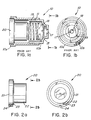
line 4b-4b of Figure 4a; - Figure 4c is a front view of another embodiment of the lens holder similar to that of Figure 4a;
- Figure 5a is a side view of the laser diode received within the positioning spring;
- Figure 5b is a front view of the laser diode received in the positioning spring of Fig. 5a, taken along
line 5b-5b of Fig. 5a; - Figure 6 is a partial sectional side view of the focusing module of the present invention showing the diode holder with the lens holder received therein;
- Figure 7 is a partial sectional side view of the focusing module of the present invention showing the diode holder and lens holder with the lens holder received by the lens holder; and
- Figure 8 is a cutaway side view of the operation of the completely assembled focusing module, with a laser diode mounted therein.
- Referring now in specific detail to the drawings, in which identical reference numerals identify similar or identical elements throughout the several views, in Figures 2a and 2b, there is shown a
laser diode 20 which provides the divergent laser light to be focused by the present invention. - The
laser diode 20 is a typical structure of laser diodes available commercially. Commercially available laser diodes structured in this manner include the Non-Contact L58300/L56100 by Sony or Toshiba, or the Non-Contact L58500 by Sony or Toshiba. - The dimensions given in the following description correspond to a particular representative embodiment of a focusing module, constructed according to the present invention, and are in no way to be considered as limiting. The dimensions given would enable the use of the focusing module with the above mentioned laser diodes.
- Referring to Figures 1a and 1b, which show in-house state of the art, the
laser diode 20 is shown with the prior art embodiment of a focusingmodule 10, having a threaded interface 11 between members 10A and 10B, which allows for focusing. Thelens glass 18 is urged by aspring 19 to rest directly on the slopedseating portion 15 of member 10B, which is also provided withemission opening 17, circular in shape and of considerably smaller diameter thanlens glass 18. Focusing ofprior art module 10 is accomplished by rotation of member 10B with respect to member 10A. - Figures 3-8 show a particular embodiment of the focusing module of the present invention. As best shown in Figures 6-8, the focusing
module 100 of the present invention has adiode holder 30, alens holder 40, and a lens assembly 60 which seats at the front end of the interior oflens holder 40. - Referring to figures 3a, 3b, and 3c, the
diode holder 30 of the focusingmodule 100 is shown. Thediode holder 30 is preferably of thin-walled construction as seen in Figures 3a and 3b, and has a firstannular portion 35 and a secondannular portion 31 of smaller radius than firstannual portion 35. In the representative embodiment, firstannular portion 35 is on the order of 9 mm (355 mil) in inner diameter, and secondannular portion 31 is on the order of 8.3 mm (326 mil) in inner diameter, both having a tolerance of approximately 0.025 mm (1 mil). - The
diode holder 30 andlens holder 40 are typically made of a light gauge metal, such as brass, and are preferably spin formed using standard spin forming and cutting techniques, but may also be formed by other known techniques such as stamping. Thesemembers - Figure 3a shows a front or radial view of the
diode holder 30 and demonstrates that the tubular shape of thediode holder 30 is primarily hollow. The thickness of the walls of the firstannular portion 35 may be on the order of 0.15 mm (6 mil), for example, and is therefore relatively thin compared to the diameter of the firstannular portion 35. The cross-section shows the secondannular portion 31 having a thickness likewise on the order of 0.15 mm (6 mil) and is therefore relatively thin compared to the diameter of the secondannular portion 31. The firstannular portion 35 and the secondannular portion 31 connect through the sloping washer-shapedsurface 33 whose radial surface has a width on the order of 0.15 mm (6 mil) and extends axially on the order of 0.5 mm (20 mil). - Referring to Figure 3b, in the representative embodiment the first
annular portion 35 extends axially on the order of 3.2 mm (125 mil), for example. The entire length of thediode holder 30 which is the net length of the firstannular portion 35 and the secondannular portion 31 is on the order of 8.3 mm (325 mil). - Spaced equidistantly around the first
annular portion 35 are a series of indentations extending radially inward, shown in Figures 3a, 3b, and 3c as a series ofpunches punches shear portions punch 36 of Figure 3b. Theseshear portions base 21 of thelaser diode 20 in the focusingmodule 100. To achieve proper axial orientation between the focusingmodule 100 and thelaser diode 20 the distance between theshear portions annular portion 35 is uniform and is preferably equivalent to the axial length ofbase 21 ofdiode 20, and generally is on the order of 1.2 mm (46 mil) with a tolerance of 0.025 mm (1 mil), in the representative embodiment. - The first
annular portion 35 also has an inward indentation or groove 32 extending in the axial direction along the length of the first annular portion, as shown in Figures 3a-3c, and is best seen in Figure 3c which clearly shows thegroove 32 extending in the axial direction. Thegroove 32 extends inward radially so that its innermost extension has approximately the same radial distance as the inner radius of the secondannular portion 31, the latter on the order of 8.3 mm (326 mil). Thegroove 32 interfaces with anotch 24 shown in Figures 2a and 2b, extending in the axial direction the length ofbase 21 of thelaser diode 20 thereby preventing rotation of thediode 20 with respect to the center axis of thediode holder 30 when thediode 20 is received in thediode holder 30. Referring back to Figures 3a, 3b, and 3c, theinward groove 32 is stamped intodiode holder 30 or pressed into the holder by a pressing operation. - Referring to Figures 4a, 4b and 4c, the
lens holder 40 of the focusing module is shown, and as best seen in Figures 4a and 4b, thelens holder 40 has aflange portion 41, a rear annular portion 41A of radius smaller than theflange 41, and a forwardannular portion 43 of radius smaller than the rear annular portion. The radially positioned washer-like surface connecting the rear annular portion 41A and the forwardannular portion 43 forms theseating surface 42 for the lens assembly 60 in as shown in Figure 7 and described below. The front end of thelens holder 40 is a closed disk-like surface 44 with anopening 45 through which the laser light is emitted and which corresponds in shape to the cross-sectioned shape of the laser light beam. This shape is generally an oblong shape, such as but not limited to, an ellipsoidal shape. In Figure 4a, threecuts flange 41, are shown and their function will be described below. In the projection along the center axis of Figure 4a, the linear midpoint of these cuts is tangent to the outer surface of the rear annular portion 41A. This is also shown in Figure 4b, where thecut 46 conforms to the cut portion of theflange 41 and rear annular portion at the particular cross-section of Figure 4b. Theflange 41 further has aradially extending notch 49, which as seen in Figure 4a, extends radially inward so that its innermost radial extension is approximately equivalent to the outer radius of the rear annular portion 41A. In a second embodiment of thelens holder 40 shown in Figure 4c, thecuts - The
ellipsolidal opening 45 oflens holder 40 has its center point aligned with the central axis of thelens holder 40. The semi-major axis ofellipsoidal opening 45 bisectsfitting notch 49 and also bisects cut 46 offlange 41 in the two dimensional projection in Figure 4a. The semi-major axis of theellipsoidal opening 45 in the representative embodiment may be approximately 4.1 mm (160 mil) and the semi-minor axis may be approximately 0.9-1.3 mm (35-50 mil), depending on the particular laser diode used. - The
lens holder 40 is received within thediode holder 30 as shown in Figure 6. To achieve reception, the closedfront end 44 of thelens holder 40 is moved coaxially into the radial opening of thediode holder 30 defined by the firstannular portion 35 toward the radial opening at the opposite end of thediode holder 30 defined by the secondannular portion 31. The rear annular portion 41A of thelens holder 40 has an outer radius only marginally smaller than the secondannular portion 31 of thediode holder 30 thereby having a frictional engagement and maintaining the coaxial positioning of thediode holder 30 and thelens holder 40. The firstannular portion 35 of thediode holder 30 receives the flange 41 (not shown in Figure 6) of thelens holder 40. Theflange 41 has radius marginally smaller than the radius of the firstannular portion 35 thereby allowing reception. However, theflange 41 has radius larger than the secondannular portion 31 of thediode holder 30 thereby preventing further reception in the axial direction of thelens holder 40 by thediode holder 30 when theflange 41 comes in contact with the washer-like surface 33 of thediode holder 30. Theflange 41 freely travels in an axial direction pastpunches annular portion 35 due to thecuts flange 41. - The received
lens holder 40 is prevented from rotating about the center axis with respect to thediode holder 30 due to thenotch 49 in theflange 41 of the thelens holder 40 which interfaces with thegroove 32 in the firstannular portion 35 of thediode holder 30. - Referring again to Figures 4a, 4b, and 4c, the
lens holder 40 has relative dimensions as defined above as well as the following for the representative embodiment: the thickness of theflange 41 rear annular portion 41A and forwardannular portion 43 are on the order of 0.15 mm (6 mil). Theseating surface 42 has a surface width of approximately 0.9 mm (37 mil), and a tolerance of approximetaly 0.025 mm (1 mil). Theseating surface 42 is normal to the central axis except for the bending at the point of contact with theannular portions 41A and 43. The inner diameter of the forwardannular portion 43 is on the order of 6.4 mm (250.5 mil), with a tolerance on the order of 0.025 mm (1 mil). The outer diameter of the rear annular portion 41A is on the order of 8.3 mm (324.8 mil) with tolerance on the order of 0.013 mm (.5 mil). The outer diameter of theflange 41 is on the order of 9 mm (352.5 mil) with tolerance of the order of 0.013 mm (.5 mil). The length of the rear annular portion 41A is approximately 6.7 mm (262 mil) with a tolerance of approximately 0.025 mm (1 mil). The length of the forwardannular portion 43 is approximately 1.7 mm (66 mil) with a tolerance on the order of 0.025 mm (1 mil). - Referring to Figures 5a and 5b, the
positioning spring 28 of the focusingmodule 100 is shown interfacing with the base of thelaser diode 20. Thepositioning spring 28 receives thecylindrical extension 22 of thediode 20. Thepositioning spring 28 has an unextended radius relatively smaller than thecylindrical extension 22; therefore the portion of thepositioning spring 28 receiving thelaser diode 20 provides an inward radial force on thebase 21 of thediode 20 and the non-receiving portion of thepositioning spring 28 tapers along its length. Thepositioning spring 28 receives thecylindrical extension 22 completely, so that one end of thepositioning spring 28 rests on theledge 23 of thebase 21 of thelaser diode 20. - Figure 7 shows the lens assembly 60 of the focusing
module 100 positioned in the focusingmodule 100. Shown in Fig. 7 is thelens holder 40 received in thediode holder 30 as described above with reference to Fig. 6. The focusinglens glass 63 is an integral part of lens assembly 60 and the central axis of the focusinglens 63 coaxially positioned with respect to the central axis of the lens assembly 60. Such lens assemblies are available commercially, and the model A-365 manufactured by Kodak is used in a preferred embodiment. The lens assembly 60 has an outer radius smaller than the rear annular portion 41A of thelens holder 40 but larger than the radius of the forwardannular portion 43; the front face 64 of the lens assembly 60 rests upon theseating surface 42 providing an axial stop for the lens assembly 60. A ring extension 62 of the lens assembly 60 has outer diameter only marginally smaller than forwardannular portion 43 thereby preventing radial movement of the lens assembly 60 with respect to thelens holder 40 and achieving a coaxial positioning of the focusing lens assembly 60, thediode holder 30, andlens holder 40. - Referring to Figure 8, as described above, the
diode holder 30 cannot rotate with respect to the receiveddiode 20 and the receivedlens holder 40 cannot rotate with respect to thediode holder 30. Accordingly, theellipsoidal opening 45 cannot be rotated axially with respect to thelaser diode 20 and the cross-section of the emitted laser light approximately matchesopening 45. - When the
laser diode 20 is received in the focusingmodule 100 thepositioning spring 28 is compressed against the lens assembly 60 forcing it in the axial direction againstseating surface 42. The forward force against the seating surface is transmitted to thediode holder 30 at the washer-like surface 33 of thediode holder 30 by theflange 41 of thelens holder 40. This results in a forward axial force on thediode holder 30 with respect to thebase 21 of thelaser diode 20; therefore to receive thelaser diode 20 in the diode holder 30 a force (shown as F1 and F2) is provided at the closedfront end 44 to counteract this resulting force from the compressedpositioning spring 28. When the force enables maximum reception of thebase 21 of thelaser diode 20 as defined by thepunches annular portion 35 of thediode holder 30 an adherent is applied at points where thebase 21 of thelaser diode 20 is received and allowed to cure, thereby affixing thebase 21 of thelaser diode 20 to thediode holder 30. - With the
laser diode 20 affixed, the compressedpositioning spring 28 forces forward axial movement of thelens holder 40 until theflange 41 rests on the washer-like surface 33 ofdiode holder 30. With thelaser diode 20 energized, light emitted with an axial component passes through the lens assembly 60 and through theellipsoidal opening 45. The focusing is adjusted by reapplying a force (shown in Figure 8 as F1 and F2) at the closedfront end 44 oflens holder 40, thereby sliding thelens holder 40 and lens assembly 60 in a rearward axial direction with respect to thediode holder 30. When focusing is achieved, forces F1 and F2 may be adjusted slightly due to the tolerances in the cylindrical members, which causes the central axis of the lens to be concentrically aligned with the central axis of the light emission, thereby achieving a symmetric intensity pattern. Once achieved, adherents such as described above are applied at points where thediode holder 30 and thelens holder 40 contact, and allowed to cure before the force is removed so that precise focusing is maintained.
Claims (37)
- A focusing module (100) particularly adapted for use with a laser diode assembly including a laser diode (20) for emitting a laser beam having a non-radially symmetric cross-section, comprising:a) a cylindrical assembly holder (30) for said laser diode assembly having a first open end defining a first annular portion (35) for receiving said laser diode assembly and a second open end defining a second annular portion (31) of smaller diameter than that of said first annular portion (35), said assembly being arranged to concentrically receive said laser diode assembly therein and adapted to orient the laser beam cross section with respect thereto and prevent axial movement and rotation of said laser diode assembly also with respect thereto;b) a cylindrical lens holder (40) adapted to slide co-axially and concentrically within said cylindrical assembly holder (30) and extend from said second open end of said cylindrical assembly holder (30), said lens holder (40) having an open end defining a first annular portion (35) of a diameter similar to but smaller than the diameter of said second annular portion (31) of said cylindrical assembly holder (30), and a closed end having an aperture (45);c) an optical lens assembly particularly adapted for use with said laser diode assembly being mounted in said lens holder; andd) means for providing an axial force for urging said lens assembly into engagement with said seating portion (42),
whereby said lens holder (40) may be axially moved and positioned within said assembly holder (30) to focus the laser beam after said laser beam passes through said lens assembly and said aperture (45) prior to securement of said lens holder (40) to said assembly holder (30) in a focused state;
characterized in that said closed end of said lens holder defines a second annular portion (31) of a diameter smaller than that of said first annular portion (35) of lens holder (40); that said lens assembly is mounted within a seating portion (42) connecting said first and second annular portions (35, 31) of said lens holder (40); and
that said lens holder (40) and said assembly holder (30) both have means to interface with each other at said open end of the lens holder (40) to prevent rotation of said lens holder (40) with respect to said assembly holder (30). - The focusing module (100) according to Claim 1, wherein said laser diode assembly is a cylindrical container having an aperture (45) on a planar end thereof through which said laser beam is emitted.
- The focusing module (100) according to Claim 1 or 2, wherein said first annular portion (35) of said cylindrical assembly holder (30) includes inwardly extending indentations which limit the reception of said laser diode assembly.
- The focusing module (100) according to Claim 3, wherein said inwardly extending indentations are formed by shearing said first annular portion (35) such that said indentations are punched at points equidistant about the circumference of said first annular portion (35).
- The focusing module (100) according to any of Claims 1-4, wherein said seating portion is perpendicular to said portions (35,31).
- The focusing module (100) according to any of Claims 1-5, wherein said first and second annular portions (35, 31) of said cylindrical assembly holder (30) are connected by an integral wall member perpendicular to said first and second annular portions (35, 31).
- The focusing module (100) according to any of Claims 1-6, wherein said cylindrical assembly (30) holder includes a radially inwardly directed groove extending axially along the length of said first annular portion (35) of said cylindrical assembly holder (30) for mating with a corresponding fitting notch provided in a flange extending about said open first end of the lens holder.
- The focusing module (100) according to Claim 7, wherein said means for providing an axial force comprises spring means (28) having first and second ends.
- The focusing module (100) according to any of Claims 1-8, wherein a first end of said spring means (28) contacts said laser diode assembly and a second end of said spring means contacts said lens assembly.
- The focusing module (100) according to Claim 9, wherein said first end of said spring means (28) rests against a base portion of said laser diode assembly, and wherein said spring means is in compression when said focusing module is assembled.
- The focusing module (100) according to Claim 10, wherein said spring means (28) is a spring (28) which continuously tapers in decreasing radius in the axial direction toward the second end of said spring 28.
- The focusing module (100) according to Claim 11, wherein said aperture (45) said lens holder has an oblong shape for emission of light from said laser diode assembly.
- The focusing module (100) according to any of Claims 1-12, wherein said aperture (45) of said lens holder has rectangular shape.
- The focusing module (100) according to Claim 13, wherein said assembly holder (30) and said lens holder are constructed of a metallic material.
- The focusing module (100) according to any of Claims 1-14, wherein said metallic material is selected from the group consisting of brass, aluminum and light-gauge steel.
- The focusing module (100) according to Claim 15, wherein said assembly holder (30) and said lens holder are molded of thermoplastic material.
- The focusing module (100) according to any of Claims 1-16, wherein said assembly holder (30) is secured to said lens holder in said focused state by welding, soldering, gluing or the like.
- The focusing module (100) according to any of Claims 1-17, wherein said laser diode assembly is secured to said assembly holder (30) by crimping, staking, welding, soldering, gluing or the like.
- The focusing module (100) according to any of Claims 1-18, wherein said laser diode assembly has a base portion (21) having means for interfacing with said first annular portion of said assembly holder (30) to prevent rotation of said laser diode assembly with respect to said assembly holder (30), said means for interfacing comprising an axially extending fitting notch corresponding to said groove in said assembly holder (30).
- The focusing module (100) according to any of Claims 1-19, wherein said assembly holder (30) and said lens holder (40) are frictionally engaged to allow for adjustment of said lens holder (40) with respect to said assembly holder (30) along a central axis of said assembly holder (30) and said lens holder (40) to achieve focusing of the emitted light from said laser diode assembly.
- A method of focusing a laser beam emitted from a laser diode assembly, comprising the steps of:a) providing a first cylindrical housing member (30) having two open ends for frictionally and slidably receiving a second cylindrical housing member (40) therein, said second housing member (40) having an open end and a closed end, said closed end positioned remote from said first housing member (30) and having an aperture (45), said second housing member (40) further having an optical lens element (63) mounted therein adjacent said closed end;b) providing said laser diode assembly within said first housing member (30) and secured thereto, and maintaining a concentric axial alignment between said laser diode assembly, said first housing member (30), said second housing member (40), and said lens element (63);c) providing an axial force urging said lens element away from said laser diode assembly within said first and second housing members (30, 40);d) slidably reciprocating said second cylindrical housing member (40) within said first cylindrical housing member (30) along an axis of said concentric axial alignment, thereby varying the distance between said laser diode assembly and said lens element (63) for focussing the laser beam on a predetermined image plane;
wherein said second cylindrical housing member (40) and said first housing member (30) both have means to interface with each other at said open end of said second member (40) to prevent rotation of said second member (40) with respect to said first member (30)e) securing said second housing member to said first housing member (30) subsequent to focusing to maintain said laser beam in focus on said image plane. - A method according to Claim 21, wherein said laser diode assembly is a cylindrical container having an exit window on a planar end thereof through which said laser beam is emitted.
- A method according to Claim 21 or 22, wherein said lens element (63) is seated within said second housing member (40) at an annular portion of reduced diameter at said closed end of said second housing member (40).
- A method according to any of Claims 21-23, wherein said laser diode assembly is received within a first annular portion of said first housing member (31) and is limited by inwardly extending indentations in said first annular portion.
- A method according to any of Claims 21-24, wherein said reciprocating step allows movement in an axial direction, and rotational movement in a radially direction being prevented by a radially inwardly directed groove extending axially along the length of said first annular portion of said first housing member (30) and a corresponding fitting notch provided in a flange at the open end of said second housing member (40).
- A method according to Claim 25, wherein said axial force positioning said lens element (63) within said second housing member (40) is accomplished by use of a spring (28).
- A method according to Claim 25, wherein radial rotation of said laser diode assembly is prevented by said groove and a corresponding notch in said laser diode assembly.
- A method according to any of Claims 21-27, wherein said aperture (45) at said closed end of said second housing member (40) has a rectangular shape for emission of light from said laser diode assembly.
- A method according to any of Claims 21-28, wherein said reciprocating step includes adjusting said second housing member (40) with respect to said first housing member (30) to align said axis so that a focused output has uniform intensity.
- A method of fabricating an optical component such as a laser diode assembly, comprising the steps of:a) drawing or stamping a light gauge metal material to form a first cylindrical housing member (30), said first housing member (30) having an open end;b) drawing or stamping a light gauge metal material to form a second cylindrical housing member (40), said second housing member (40) having an open end and a closed end, said closed end having an aperture (45);c) providing a first optical component within said first housing member and a second optical component in said second housing member;d) positioning said first and said second housing members (30, 40) in telescoping relationship,
whereby said second housing member (40) is adapted to slide within said first housing member (30) and said second housing member (40) and said first housing member (30) both have means to interface with each other at said open end of said second housing member (40) to prevent rotation of said second housing member (40) with respect to said first housing member (30).e) providing an axial force urging said first and second housing (30, 40) members into a fixed longitudinal spaced relationship thereby focusing a light beam transmitted between said first and said second optical components. - A method according to claim 30, further comprising the step of securing said second housing member (40) to said first housing member (30) subsequent to providing said axial force to maintain said first and second housing members (30, 40) in a fixed predetermined focus position.
- A method according to Claim 30 or 31, wherein said first optical component is a semiconductor laser diode having an exterior surface.
- A method according to any of Claims 30-32, wherein said second optical component is a lens element (63) seated at an annular portion of reduced diameter adjacent said closed end of said second housing member (40).
- A method according to Claim 32, further comprising the step of stamping inwardly extending indentations in said first housing member (30) to form a first annular portion in said first housing member (30) for receiving and positioning said laser diode therein.
- A method according to Claim 34, further comprising the step of forming a radially inwardly directed groove extending axially along the length of said first annular portion of said first housing member (30).
- A method according to any of Claim 30-35, wherein said laser diode includes a notch in said exterior surface so that when said laser diode is provided in said first housing member (30) rotation of said laser diode is prevented by engagement of said notch in said laser diode with said groove.
- A method according to any of Claims 30-36, further comprising the step of forming an aperture (45) at said closed end of said second housing member (40), said aperture having a rectangular or ellipsoidal shape.
Applications Claiming Priority (2)
| Application Number | Priority Date | Filing Date | Title |
|---|---|---|---|
| US265549 | 1988-11-01 | ||
| US07/265,549 US4923281A (en) | 1988-11-01 | 1988-11-01 | Laser diode focusing module, method of fabricating, and method of using |
Publications (3)
| Publication Number | Publication Date |
|---|---|
| EP0366984A2 EP0366984A2 (en) | 1990-05-09 |
| EP0366984A3 EP0366984A3 (en) | 1991-01-09 |
| EP0366984B1 true EP0366984B1 (en) | 1995-04-12 |
Family
ID=23010921
Family Applications (1)
| Application Number | Title | Priority Date | Filing Date |
|---|---|---|---|
| EP89118907A Expired - Lifetime EP0366984B1 (en) | 1988-11-01 | 1989-10-11 | Laser diode focusing module for divergent light source |
Country Status (5)
| Country | Link |
|---|---|
| US (1) | US4923281A (en) |
| EP (1) | EP0366984B1 (en) |
| JP (1) | JPH087311B2 (en) |
| CA (1) | CA2001586C (en) |
| DE (1) | DE68922180T2 (en) |
Families Citing this family (29)
| Publication number | Priority date | Publication date | Assignee | Title |
|---|---|---|---|---|
| US5374817A (en) * | 1988-05-11 | 1994-12-20 | Symbol Technologies, Inc. | Pre-objective scanner with flexible optical support |
| US5479000A (en) * | 1989-10-30 | 1995-12-26 | Symbol Technologies, Inc. | Compact scanning module for reading bar codes |
| US5552592A (en) * | 1989-10-30 | 1996-09-03 | Symbol Technologies, Inc. | Slim scan module with dual detectors |
| US5367151A (en) * | 1989-10-30 | 1994-11-22 | Symbol Technologies, Inc. | Slim scan module with interchangeable scan element |
| US5422469A (en) * | 1989-10-30 | 1995-06-06 | Symbol Technologies, Inc. | Fiber optic barcode readers using purely mechanical scanner oscillation |
| US5373148A (en) * | 1989-10-30 | 1994-12-13 | Symbol Technologies, Inc. | Optical scanners with scan motion damping and orientation of astigmantic laser generator to optimize reading of two-dimensionally coded indicia |
| US5404001A (en) * | 1992-10-08 | 1995-04-04 | Bard; Simon | Fiber optic barcode reader |
| US5113290A (en) * | 1990-12-13 | 1992-05-12 | Honeywell Inc. | Sealed focusing assembly for an industrial vision system |
| CA2068022C (en) * | 1991-09-17 | 2002-07-09 | Norbert M. Stiepel | Surveillance device with eyeball assembly and pivotably mountable carriage assembly |
| DE4305633A1 (en) * | 1992-02-24 | 1993-10-07 | Valeo Vision | Headlamp with two-part lens holder esp for motor vehicle - has relative positions of lens and reflector fixed by heat-dissipating assembly which grips lens between coaxial collars |
| US20030043463A1 (en) * | 1992-03-30 | 2003-03-06 | Yajun Li | Athermalized plastic lens |
| US6092728A (en) * | 1992-03-30 | 2000-07-25 | Symbol Technologies, Inc. | Miniature laser diode focusing module using micro-optics |
| US5418700A (en) * | 1992-07-22 | 1995-05-23 | Corning Incorporated | Laser light source module and method |
| US5331143A (en) * | 1992-08-28 | 1994-07-19 | Symbol Technologies, Inc. | Optical scanner using an axicon and an aperture to aspherically form the scanning beam |
| US5905751A (en) * | 1997-09-15 | 1999-05-18 | Quarton, Inc. | Laser modules and methods of manufacturing same |
| USD416926S (en) * | 1998-09-08 | 1999-11-23 | Asahi Kogaku Kogyo Kabushiki Kaisha | Lens for single-lens reflex camera |
| US6205160B1 (en) | 1998-09-24 | 2001-03-20 | Branson Ultrasonics Corporation | Laser diode array |
| EP1096415A1 (en) | 1999-10-26 | 2001-05-02 | Datalogic S.P.A. | Optical device, lens and optical element for focusing a laser beam and apparatus and method for assembling the optical device |
| JP3954332B2 (en) * | 2000-07-17 | 2007-08-08 | 株式会社東芝 | Optical lens unit and camera module |
| US6637657B2 (en) | 2001-04-06 | 2003-10-28 | Symbol Technologies, Inc. | Compact scan module with magnetically centered scan mirror |
| US20050180486A1 (en) * | 2004-02-13 | 2005-08-18 | Tung Hsin C. | Laser module for circular saw |
| CN100368849C (en) * | 2005-01-20 | 2008-02-13 | 亚洲光学股份有限公司 | Laser light-emitting assembly and adjusting device for laser light-emitting assembly |
| US7114861B1 (en) * | 2005-05-09 | 2006-10-03 | Lecc Technology Co., Ltd. | Laser module with trimming capacity |
| TWI285013B (en) * | 2006-01-03 | 2007-08-01 | Quarton Inc | Laser module and method of manufacturing the same |
| TWM303564U (en) * | 2006-04-21 | 2006-12-21 | Arima Optoelectronics Corp | Optic unit for laser module |
| CN106197386B (en) * | 2016-06-22 | 2018-12-21 | 北京航空航天大学 | A kind of thruster central axis simulator suitable for different bores |
| USD846620S1 (en) * | 2017-01-05 | 2019-04-23 | Panasonic Intellectual Property Management Co., Ltd. | Video camera |
| JP2021117235A (en) * | 2020-01-22 | 2021-08-10 | キヤノン株式会社 | Lens device and imaging device |
| CN114325645B (en) * | 2021-12-17 | 2022-09-09 | 湖南阿秒光学科技有限公司 | Laser module mounting method |
Family Cites Families (17)
| Publication number | Priority date | Publication date | Assignee | Title |
|---|---|---|---|---|
| US3583742A (en) * | 1969-08-26 | 1971-06-08 | Gen Motors Corp | Door latch mechanism |
| US4281891A (en) * | 1978-03-27 | 1981-08-04 | Nippon Electric Co., Ltd. | Device for excellently coupling a laser beam to a transmission medium through a lens |
| US4387297B1 (en) * | 1980-02-29 | 1995-09-12 | Symbol Technologies Inc | Portable laser scanning system and scanning methods |
| US4496831A (en) * | 1980-02-29 | 1985-01-29 | Symbol Technologies, Inc. | Portable laser scanning system and scanning methods |
| NL182031C (en) * | 1980-11-06 | 1987-12-16 | Philips Nv | OPTICAL SYSTEM FOR DELIVERING A COLLIMATED LIGHT BEAM. |
| US4673805A (en) * | 1982-01-25 | 1987-06-16 | Symbol Technologies, Inc. | Narrow-bodied, single- and twin-windowed portable scanning head for reading bar code symbols |
| US4758717A (en) * | 1982-01-25 | 1988-07-19 | Symbol Technologies, Inc. | Narrow-bodied, single-and twin-windowed portable laser scanning head for reading bar code symbols |
| US4736095A (en) * | 1982-01-25 | 1988-04-05 | Symbol Technologies, Inc. | Narrow-bodied, single- and twin-windowed portable laser scanning head for reading bar code symbols |
| US4460120A (en) * | 1982-01-25 | 1984-07-17 | Symbol Technologies, Inc. | Narrow bodied, single- and twin-windowed portable laser scanning head for reading bar code symbols |
| US4409470A (en) * | 1982-01-25 | 1983-10-11 | Symbol Technologies, Inc. | Narrow-bodied, single-and twin-windowed portable laser scanning head for reading bar code symbols |
| US4541689A (en) * | 1983-09-19 | 1985-09-17 | Optical Storage International | Friction wedge alignment system for laser diode collimator pens |
| US4578571A (en) * | 1983-11-14 | 1986-03-25 | Numa Corporation | Portable bar code scanning device and method |
| JPS60171636A (en) * | 1984-02-17 | 1985-09-05 | Mitsubishi Electric Corp | Pickup device |
| JPS61251980A (en) * | 1985-02-28 | 1986-11-08 | シンボル テクノロジイズ インコ−ポレイテツド | Portable laser diode scanning head |
| US4709311A (en) * | 1986-07-16 | 1987-11-24 | Vari-Lite, Inc. | Lens carrier |
| US4743091A (en) * | 1986-10-30 | 1988-05-10 | Daniel Gelbart | Two dimensional laser diode array |
| US4808804A (en) * | 1987-01-28 | 1989-02-28 | Symbol Technologies, Inc. | Bar code symbol readers with variable spot size and/or working distance |
-
1988
- 1988-11-01 US US07/265,549 patent/US4923281A/en not_active Expired - Lifetime
-
1989
- 1989-10-11 EP EP89118907A patent/EP0366984B1/en not_active Expired - Lifetime
- 1989-10-11 DE DE68922180T patent/DE68922180T2/en not_active Expired - Fee Related
- 1989-10-26 CA CA002001586A patent/CA2001586C/en not_active Expired - Lifetime
- 1989-11-01 JP JP1286005A patent/JPH087311B2/en not_active Expired - Fee Related
Also Published As
| Publication number | Publication date |
|---|---|
| JPH087311B2 (en) | 1996-01-29 |
| CA2001586C (en) | 1994-07-26 |
| EP0366984A3 (en) | 1991-01-09 |
| CA2001586A1 (en) | 1990-05-01 |
| DE68922180D1 (en) | 1995-05-18 |
| US4923281A (en) | 1990-05-08 |
| JPH02250011A (en) | 1990-10-05 |
| DE68922180T2 (en) | 1995-11-30 |
| EP0366984A2 (en) | 1990-05-09 |
Similar Documents
| Publication | Publication Date | Title |
|---|---|---|
| EP0366984B1 (en) | Laser diode focusing module for divergent light source | |
| US6092728A (en) | Miniature laser diode focusing module using micro-optics | |
| US5537503A (en) | Optical semiconductor module and method of fabricating the same | |
| US5353294A (en) | Semiconductor laser device and semiconductor laser module | |
| US5074682A (en) | Semiconductor laser module and positioning method thereof | |
| US6094515A (en) | Optical module | |
| US5164584A (en) | Optical scanner with power efficient lens | |
| US6916119B2 (en) | Optical fiber connector and optical communication module using the same | |
| US5119462A (en) | Photosemiconductor and optical fiber welded module | |
| EP0718657A2 (en) | Optical switch | |
| US5189716A (en) | Photosemiconductor and optical fiber welded module | |
| US5274491A (en) | Dynamic laser diode aperture for optical scanners | |
| JPS5818653A (en) | Recording device | |
| CN115236632A (en) | Lens module, laser module and laser radar device | |
| JPS6448692A (en) | Multifocusing laser beam condensing device | |
| EP0431603A2 (en) | Optical unit for use in laser beam printer or the like | |
| JPH07168065A (en) | Optical semiconductor module | |
| CN114325645B (en) | Laser module mounting method | |
| US7903354B2 (en) | Optical scanning device and image forming apparatus having the same | |
| US6964529B2 (en) | Orientation-adjustable optical transceiver module | |
| US20010036343A1 (en) | Receptacle type optical fiber connector and optical communication module using the same | |
| JPH07281062A (en) | Semiconductor laser module | |
| JPH0933768A (en) | Optical semiconductor device | |
| JP3400749B2 (en) | Optical fiber sensor head | |
| US6893170B1 (en) | Optical/electrical module |
Legal Events
| Date | Code | Title | Description |
|---|---|---|---|
| PUAI | Public reference made under article 153(3) epc to a published international application that has entered the european phase |
Free format text: ORIGINAL CODE: 0009012 |
|
| 17P | Request for examination filed |
Effective date: 19891026 |
|
| AK | Designated contracting states |
Kind code of ref document: A2 Designated state(s): DE FR GB IT |
|
| PUAL | Search report despatched |
Free format text: ORIGINAL CODE: 0009013 |
|
| AK | Designated contracting states |
Kind code of ref document: A3 Designated state(s): DE FR GB IT |
|
| 17Q | First examination report despatched |
Effective date: 19921214 |
|
| GRAA | (expected) grant |
Free format text: ORIGINAL CODE: 0009210 |
|
| AK | Designated contracting states |
Kind code of ref document: B1 Designated state(s): DE FR GB IT |
|
| ITF | It: translation for a ep patent filed |
Owner name: JACOBACCI & PERANI S.P.A. |
|
| REF | Corresponds to: |
Ref document number: 68922180 Country of ref document: DE Date of ref document: 19950518 |
|
| ET | Fr: translation filed | ||
| PLBE | No opposition filed within time limit |
Free format text: ORIGINAL CODE: 0009261 |
|
| STAA | Information on the status of an ep patent application or granted ep patent |
Free format text: STATUS: NO OPPOSITION FILED WITHIN TIME LIMIT |
|
| 26N | No opposition filed | ||
| REG | Reference to a national code |
Ref country code: GB Ref legal event code: IF02 |
|
| PGFP | Annual fee paid to national office [announced via postgrant information from national office to epo] |
Ref country code: DE Payment date: 20071004 Year of fee payment: 19 |
|
| PGFP | Annual fee paid to national office [announced via postgrant information from national office to epo] |
Ref country code: IT Payment date: 20071026 Year of fee payment: 19 |
|
| PGFP | Annual fee paid to national office [announced via postgrant information from national office to epo] |
Ref country code: FR Payment date: 20071009 Year of fee payment: 19 Ref country code: GB Payment date: 20071010 Year of fee payment: 19 |
|
| GBPC | Gb: european patent ceased through non-payment of renewal fee |
Effective date: 20081011 |
|
| REG | Reference to a national code |
Ref country code: FR Ref legal event code: ST Effective date: 20090630 |
|
| PG25 | Lapsed in a contracting state [announced via postgrant information from national office to epo] |
Ref country code: DE Free format text: LAPSE BECAUSE OF NON-PAYMENT OF DUE FEES Effective date: 20090501 Ref country code: IT Free format text: LAPSE BECAUSE OF NON-PAYMENT OF DUE FEES Effective date: 20081011 |
|
| PG25 | Lapsed in a contracting state [announced via postgrant information from national office to epo] |
Ref country code: FR Free format text: LAPSE BECAUSE OF NON-PAYMENT OF DUE FEES Effective date: 20081031 |
|
| PG25 | Lapsed in a contracting state [announced via postgrant information from national office to epo] |
Ref country code: GB Free format text: LAPSE BECAUSE OF NON-PAYMENT OF DUE FEES Effective date: 20081011 |