EP0366518A1 - Inflatable passive seat belt with automatic buckling - Google Patents
Inflatable passive seat belt with automatic buckling Download PDFInfo
- Publication number
- EP0366518A1 EP0366518A1 EP89402796A EP89402796A EP0366518A1 EP 0366518 A1 EP0366518 A1 EP 0366518A1 EP 89402796 A EP89402796 A EP 89402796A EP 89402796 A EP89402796 A EP 89402796A EP 0366518 A1 EP0366518 A1 EP 0366518A1
- Authority
- EP
- European Patent Office
- Prior art keywords
- strap
- seat
- envelope
- keeper
- belt according
- Prior art date
- Legal status (The legal status is an assumption and is not a legal conclusion. Google has not performed a legal analysis and makes no representation as to the accuracy of the status listed.)
- Granted
Links
Images

Classifications
-
- B—PERFORMING OPERATIONS; TRANSPORTING
- B60—VEHICLES IN GENERAL
- B60R—VEHICLES, VEHICLE FITTINGS, OR VEHICLE PARTS, NOT OTHERWISE PROVIDED FOR
- B60R22/00—Safety belts or body harnesses in vehicles
- B60R22/04—Passive restraint systems, i.e. systems both applied and removed automatically, e.g. by movement of the vehicle door
-
- A—HUMAN NECESSITIES
- A44—HABERDASHERY; JEWELLERY
- A44B—BUTTONS, PINS, BUCKLES, SLIDE FASTENERS, OR THE LIKE
- A44B11/00—Buckles; Similar fasteners for interconnecting straps or the like, e.g. for safety belts
- A44B11/25—Buckles; Similar fasteners for interconnecting straps or the like, e.g. for safety belts with two or more separable parts
- A44B11/2503—Safety buckles
- A44B11/2538—Safety buckles with a pivoting bar retaining a loop of the strap itself
Landscapes
- Engineering & Computer Science (AREA)
- Mechanical Engineering (AREA)
- Air Bags (AREA)
- Automotive Seat Belt Assembly (AREA)
Abstract
Description
La présente invention concerne les ceintures de sécurité passives gonflables à bouclage automatique pour sièges de véhicules notamment automobiles terrestres.The present invention relates to passive inflatable seat belts with automatic fastening for vehicle seats, in particular for land motor vehicles.
Comme on le sait, les pouvoirs publics imposent d'équiper les sièges des véhicules, notamment terrestres ou aériens, de ceintures de sécurité.As we know, the public authorities impose to equip the seats of vehicles, in particular land or air, with seat belts.
Pour les véhicules automobiles on a déjà proposé de munir leurs sièges de ceintures de sécurité passives. Ce type de ceinture de sécurité comprend, habituellement, deux sangles indépendantes dont l'une des extrémités est reliée à un enrouleur. L'une de ces sangles se présente à la manière d'un baudrier qui repose sur le thorax de l'occupant et l'autre sangle prend appui sur l'abdomen de ce dernier. Alors que la sangle abdominale doit être attachée ou fermée manuellement, la sangle thoracique est mise en place automatiquement. Pour ce faire la sangle thoracique est fixée à un point d'ancrage supérieur de la paroi latérale de la structure du véhicule, par exemple à la portière, et à un point d'ancrage inférieur, relié habituellement à la glissière du siège selon l'axe médian du véhicule. Cette sangle thoracique est bouclée en permanence et le point d'ancrage supérieur est mobile, qu'il soit porté par la portière ou un support mobile qui se déplace dans un guide placé au-dessus de la portière du véhicule. Lors de la fermeture de la portière, le brin thoracique vient reposer automatiquement contre la poitrine de l'occupant, le point d'ancrage supérieur se déplaçant avec la portière ou son support mobile.For motor vehicles, it has already been proposed to provide their seats with passive seat belts. This type of seat belt usually includes two independent straps, one end of which is connected to a retractor. One of these straps is in the form of a harness which rests on the occupant's chest and the other strap bears on the latter's abdomen. While the abdominal strap must be attached or closed manually, the chest strap is automatically put in place. To do this, the chest strap is fixed to an upper anchor point on the side wall of the vehicle structure, for example to the door, and to a lower anchor point, usually connected to the seat rail according to the vehicle center line. This chest strap is permanently fastened and the upper anchoring point is mobile, whether it is carried by the door or a mobile support which moves in a guide placed above the vehicle door. When the door is closed, the chest strand comes to rest automatically against the occupant's chest, the upper anchor point moving with the door or its movable support.
Une autre technique qui a été proposée consiste en une ceinture de sécurité à sangles gonflables. Une solution de ceinture de sécurité de ce type est exposée dans la demande de brevet français 2 465 615. Selon ce document, la ceinture de sécurité comprend soit une sangle ventrale soit une sangle pectorale qui est faite de deux éléments distincts. Chacun de ces éléments se présente à la manière d'un tube étanche gonflable à l'aide d'un fluide par exemple gazeux. Chaque élément se trouve normalement, à l'état de repos, enroulé sur lui-même et lorsqu'une personne prend place sur le siège, la présence de celle-ci déclenche le gonflage de chacun des deux éléments. Ceux-ci se déroulent alors et se déployent à la manière d'un objet de cotillons bien connu, habituellement dénommé "sans-gène ou langue de belle-mère", utilisé aussi bien par les enfants que les adultes pour animer joyeusement les réunions auxquelles ils participent. Comme on le sait, cet objet de cotillon se compose d'un embout bucal prolongé par un tube en cul de sac étanche muni d'un ressort de rappel qui le maintien normalement enroulé en spires jointives. Lorsqu'on souffle dans l'embout, le tube se gonfle et se déroule tout en se détendant brusquement en direction du convive visé. Ces deux éléments de la sangle ainsi déployés qui se trouvent à portée de mains de l'occupant, lui occassionnent une gène qui le conduit alors à boucler manuellement la ceinture.Another technique which has been proposed consists of a seat belt with inflatable straps. A seat belt solution of this type is disclosed in French patent application 2,465,615. According to this document, the seat belt comprises either a lap strap or a chest strap which is made of two distinct elements. Each of these elements is in the form of an airtight tube inflatable with the aid of a gaseous fluid, for example. Each element is normally, in the rest state, wound on itself and when a person takes place on the seat, the presence of this triggers the inflation of each of the two elements. These then unfold and unfold in the manner of a well-known party favors object, usually called "gene-free or mother-in-law's tongue", used by children as well as adults to cheerfully facilitate meetings at which they participate. As we know, this cotillion object consists of a mouthpiece extended by a tight dead end tube provided with a return spring which keeps it normally wound in contiguous turns. When you blow into the mouthpiece, the tube swells and unwinds while suddenly relaxing towards the target guest. These two elements of the strap thus deployed which are within easy reach of the occupant, cause him a gene which then leads him to manually buckle the belt.
Pour se libérer de la ceinture qui s'est ainsi présentée à lui afin qu'il la boucle ou attache manuellement, l'occupant doit au préalable la dégonfler. On comprend donc que cette ceinture qui rappelle à l'occupant qui a pris place sur un siège qu'il doit attacher sa ceinture, n'est pas d'un fonctionnement automatique et de plus est nécessairement génant puisque c'est l'inconfort que crée la ceinture déployée qui doit obligatoirement conduire l'occupant à la boucler.To free himself from the belt which has thus presented itself to him so that he can buckle or fasten it manually, the occupant must first deflate it. It is therefore understandable that this belt which reminds the occupant who has taken place on a seat that he must fasten his belt, is not automatic and moreover is necessarily annoying since it is the discomfort that creates the deployed belt which must obligatorily lead the occupant to fasten it.
Le but de l'invention est de fabriquer une ceinture de sécurité passive gonflable à bouclage automatique pour siège de véhicule notamment terrestre, qui ne présente pas ce genre d'inconvévients.The object of the invention is to manufacture an inflatable passive safety belt with automatic fastening for a seat for a vehicle, especially a land vehicle, which does not have this type of drawback.
L'invention a pour objet une ceinture de sécurité passive gonflable à enrouleur et à bouclage automatique à l'aide d'une boucle avec pène et gâche qui est destinée à retenir un occupant assis sur son siège monté sur une structure une fois la boucle fermée. Cette ceinture de sécurité est remarquable en ce qu'elle comprend une sangle unique faite d'un ruban flexible résistant mécaniquement ainsi que d'une enveloppe souple et continue étanche à un fluide et déployable sous la pression de ce dernier qui est associée à ce ruban sur au moins la partie de celui-ci la plus éloignée de l'enrouleur et dont cette partie où enveloppe et ruban sont présents est divisée en un brin thoracique et en un brin abdominal qui sont séparés par le pène de la boucle, des dispositifs d'amarrage pour relier l'une des extrémités de la sangle à l'enrouleur et l'autre des extrémités de celle-ci à l'un de ces siège et structure et pour ancrer la gâche de la boucle à l'un de ces derniers, des moyens de mise en pression pour gonfler ou dégonfler cette enveloppe et une unité de commande pour faire fonctionner ces moyens de mise en pression de manière que lorsqu'un occupant s'est assis sur son siège l'unité de commande déclenche le fonctionnement des moyens de mise en pression pour gonfler l'enveloppe et dérouler la sangle qui en se déployant progressivement entoure l'occupant et dirige le pène de la boucle vers la gâche de celle-ci afin qu'il s'y accroche automatiquement et de manière que lorsque le pène et la gâche de la boucle sont accrochés l'un à l'autre l'unité de commande arrête le fonctionnement des moyens de mise en pression pour dégonfler l'enveloppe afin que l'enrouleur tende la sangle pour l'appliquer contre l'occupant.The subject of the invention is an inflatable passive retractable seat belt with automatic fastening using a buckle with bolt and keeper which is intended to restrain an occupant seated in his seat mounted on a structure once the buckle is closed . This seat belt is remarkable in that it includes a single strap made of a flexible, mechanically resistant tape as well as a flexible and continuous envelope which is fluid tight and deployable under the pressure of the latter which is associated with this tape. on at least the part of it furthest from the retractor and of which this part where envelope and ribbon are present is divided into a thoracic strand and an abdominal strand which are separated by the bolt of the loop, 'mooring to connect one end of the strap to the reel and the other end of the latter to one of these seat and structure and to anchor the keeper of the buckle to one of these , pressurizing means for inflating or deflating this envelope and a control unit for operating these pressurizing means so that when an occupant is seated in his seat the control unit triggers the function nning of the pressurizing means for inflating the envelope and unwinding the strap which, progressively unfolding, surrounds the occupant and directs the bolt of the buckle towards the keeper of the latter so that it clings to it automatically and so that when the bolt and the keeper of the loop are hooked one to the other control unit stops the operation of the pressurizing means to deflate the envelope so that the reel tightens the strap to apply it against the occupant.
D'autres caractéristiques de l'invention ressortiront de la lecture de la description et des revendications qui suivent et de l'examen du dessin annexé, donné seulement à titre d'exemple où :
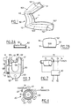
- - la Fig.1 est une vue perspective partielle d'un mode de réalisation d'une sangle de ceinture de sécurité selon l'invention;
- - les Figs.2A et 2B sont des sections transversales du mode de réalisation de la Fig.1 respectivement à l'état dégonflé et à l'état gonflé ;
- - la Fig.3 est une vue schématique d'un mode de réalisation d'une gâche de boucle de ceinture de sécurité selon l'invention ;
- - la Fig.4 est une vue latérale schématique d'un mode de réalisation d'un enrouleur de ceinture de sécurité selon l'invention ;
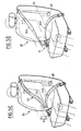
- - les Fig.5A, 5B, 5C et 5D sont des vues perspectives schématiques illustrant le fonctionnement d'une ceinture de sécurité selon l'invention dans différentes phases de sa mise en oeuvre ;
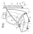
- - la Fig.6 est une vue analogue à celle de la Fig.5C d'un autre mode de réalisation d'une ceinture de sécurité selon l'invention ; et
- - la Fig.7 est une vue schématique illustrant les moyens de mise en pression et l'unité de commande de la ceinture de sécurité selon l'invention.
- - Fig.1 is a partial perspective view of an embodiment of a seat belt strap according to the invention;
- - Figs.2A and 2B are cross sections of the embodiment of Fig.1 respectively in the deflated state and in the inflated state;
- - Fig.3 is a schematic view of an embodiment of a seat belt buckle keeper according to the invention;
- - Fig.4 is a schematic side view of an embodiment of a seat belt retractor according to the invention;
- - Fig.5A, 5B, 5C and 5D are schematic perspective views illustrating the operation of a seat belt according to the invention in different phases of its implementation;
- - Fig.6 is a view similar to that of Fig.5C of another embodiment of a seat belt according to the invention; and
- - Fig.7 is a schematic view illustrating the pressurizing means and the seat belt control unit according to the invention.
Les ceintures de sécurité notamment pour véhicules automobiles terrestres étant bien connues dans la technique, on ne décrira dans la suite que ce qui concerne directement ou indirectement l'invention. Pour le surplus, le spécialiste du domaine technique considéré puisera dans les solutions classiques courantes à sa disposition pour faire face aux problèmes particuliers auxquels il est confronté.As seat belts, in particular for land motor vehicles, are well known in the art, we will describe hereinafter only that which relates directly or indirectly to the invention. For the rest, the specialist in the technical field under consideration will draw on the current conventional solutions at his disposal to deal with the particular problems with which he is confronted.
Dans ce qui suit un même numéro de référence désigne toujours un même élément quel que soit le mode de réalisation de l'invention.In what follows, the same reference number always designates the same element whatever the embodiment of the invention.
Comme cela ressort clairement de l'examen des figures du dessin, une ceinture de sécurité passive gonflable à rappel et bouclage automatiques selon l'invention comprend une boucle 10, un enrouleur 20 associé à un siège 30 ou à une structure 40 sur laquelle il est monté. Cette boucle 10 et cet enrouleur 20 sont destinés à être reliés par une sangle 50; cette sangle est fixée par des dispositifs d'amarrage 60, d'une part, à l'enrouleur et, d'autre part, à l'un de ces siège et structure. Des moyens de mise en pression 70, pour gonfler ou dégonfler la sangle, sont sous la dépendance d'une unité de commande 80.As is clear from examining the figures in the drawing, an inflatable passive safety belt with automatic return and fastening according to the invention comprises a
Pour la commodité de l'exposé en décrira successivement chacun de ces constituants d'une ceinture de sécurité passive gonflable à rappel et bouclage automatiques selon l'invention avant d'en indiquer le fonctionnement.For the convenience of the description, each of these constituents of a passive inflatable seat belt with automatic return and fastening according to the invention will be described successively before indicating its operation.
Cette ceinture de sécurité est destinée à être associée à un siège 30 qui comprend, comme il est classique, une assise 31, un dossier 32 et s'il y a lieu un repose-tête ou têtière 33.This seat belt is intended to be associated with a
Ce siège 30 est habituellement monté dans une structure 40 telle que la coque ou la carrosserie d'un véhicule automobile. Cette structure 40 comprend par exemple une paroi latérale 41 ici seulement schématisée par le pied ou montant milieu situé entre les portières avant et arrière d'un véhicule automobile. Cette structure comprend aussi un plancher 42 sur lequel sont fixées des glissières 43 dont des éléments complémentaires coopérants sont montés pour partie sur celui-ci et pour partie sous l'assise du siège ; de cette manière il est possible de régler la position longitudinale du siège dans le véhicule comme il est classique.This
L'enrouleur 20, auquel l'une des extrémités de la sangle de la ceinture est fixée, est destiné à rappeler automatiquement la sangle de manière à maintenir en permanence celle-ci sous une tension déterminée y compris lorsqu'un occupant est assis sur son siège. De cette manière la sangle est maintenue en permanence tendue contre le corps de l'occupant tout en lui permettant de bouger sans contrainte. Comme il est classique, un tel enrouleur à rappel élastique automatique est sous la dépendance d'un système de blocage à commande inertielle qui interdit de déroulement de la sangle en cas de décélération violente du véhicule ou d'accélération tangentielle importante de la sangle.The
Comme on le voit en particulier sur la Fig.4, et pour les raisons qui apparaîtront par la suite, le mode de réalisation représenté schématiquement d'un enrouleur 20 comprend un tambour 21 soumis à un couple de rappel élastique comme il est connu, des galets supports 22 disposés à la périphérie de ce tambour et à distance de ce dernier, ainsi qu'un cylindre presseur 23. Ce cylindre 23 est porté par un levier 24 articulé à l'une de ses extrémités et monté de manière à pouvoir basculer. Ce levier 24 est sollicité par un ressort 25 de manière que le cylindre presseur soit normalement sollicité en direction du tambour 21. La sangle 50 est enroulée comme clairement illustré.As can be seen in particular in FIG. 4, and for the reasons which will appear subsequently, the embodiment shown diagrammatically of a
La boucle 10 comprend un pène 11 sur lequel on reviendra en détail par la suite et qui résulte notamment d'une configuration spéciale obtenue par une structure particulière locale donnée à la sangle. Cette boucle comprend aussi une gâche 12. Cette gâche 12 comprend un corps 120 en U dont les deux branches 121 parallèles sont reliées par un pont 122 percé d'un trou 123 pour son ancrage, grâce à une technique classique et pour cela non illustrée afin de solidariser la gâche au siège 30 ou à la structure 40. Ce corps 120 porte un loquet 124 qui est monté basculant à l'aide d'un axe 125 et qui est rappelé élastiquement en position de fermeture par un ressort 126. Cette gâche comprend, aussi, un bouton 13 de commande d'ouverture. Ce bouton 13 comprend une tringle 130 ou analogue coudée approximativement en forme de C comme illustré à laquelle est fixé un poucier 131. Cette tringle 130 porte un arrêtoir 132 destiné à coopérer avec le loquet 124 et est soumise à l'action d'un ressort de rappel 133. Ce bouton de commande 13 est monté coulissant de toute manière appropriée classique sur le corps 120 de la gâche.The
Tout ceci est illustré en détail, schématiquement sur la Fig.3.All this is illustrated in detail, schematically in Fig. 3.
Cette boucle 10 est normalement sollicitée dans la position de fermeture illustrée où l'arrêtoir 132 du bouton de commande retient le loquet 124 pour l'empêcher de basculer dans le sens opposé au pont 122. Lorsque le pène 11 est introduit entre les deux branches 121 du U et entre le pont 122 et le loquet 124 il ne peut donc s'en échapper. Pour libérer le pène 11 de la gâche 12 et ainsi pour ouvrir la boucle 10, il suffit de presser sur le poucier 131 pour faire reculer l'arrêtoir 132 qui se sépare alors du loquet 124 et le libère. Le loquet 124 peut alors basculer dans le sens opposé à celui des aiguilles d'une montre (Fig.3) sous la tension de la sangle ou une traction exercée sur celle-ci, dans le sens opposé au pont 122: le pène 11 est alors libre de sortir de la gâche 12 pour détacher la ceinture.This
Comme cela apparaît en particulier sur la Fig.1 et les Fig.2A et 2B, une sangle 50 pour ceinture de sécurité selon l'invention comprend un ruban 51 inextensible et flexible ayant une très bonne résistance mécanique. C'est ce ruban qui en cas de collision supporte et transmet indirectement les efforts communiqués par l'occupant qui tend à quitter son siège, à la structure. L'une des extrémités de la sangle, par exemple de ce ruban 51, est fixée à l'enrouleur 20 plus spécialement à son tambour 21, et l'autre de ses extrémités est fixée à l'un de ces siège 30 ou structure 40 ; ces fixations sont faites à l'aide des dispositifs d'amarrage 60. A ce ruban 51, et plus particulièrement à la partie de celui-ci qui est la plus éloignée de l'enrouleur 20, est associée une enveloppe 52 tubulaire souple et étanche à un fluide de préférence gazeux, par exemple de l'air. Cette enveloppe 52 tubulaire, par exemple déployable élastiquement, se présente à l'état dégonflé comme illustré sur la section droite de la Fig.2A, et à l'état gonflé, cette enveloppe se présente comme illustré sur la Fig.2B. L'extrémité de cette enveloppe 52 qui est dirigée vers l'enrouleur 20 est fermée en cul de sac et son extrémité opposée est munie d'un embout sur lequel on reviendra par la suite. Comme on le voit, l'enveloppe 52 présente une paroi antérieure 521 et une paroi postérieure 522 qui est destinée à faire face au corps de l'occupant c'est-à-dire aussi au siège 30. Ces parois antérieure et postérieure ont des longueurs, dans le sens longitudinal ou dans le sens "chaîne" de la sangle, différentes: la longueur de la paroi postérieure 522 est plus courte que la longueur de la paroi antérieure 521 pour les raisons qui apparaîtront par la suite. De préférence, cette enveloppe 52 a une section droite transversale approximativement rectangulaire en position gonflée. Cette section transversale va, de préférence, en décroissant depuis l'extrémité comportant l'embout vers l'extrémité opposée où se trouve l'enrouleur.As appears in particular in FIG. 1 and FIGS. 2A and 2B, a
La partie de la sangle 50 qui comprend à la fois le ruban 51 et l'enveloppe 52 est divisée en un brin thoracique 501 et un brin abdominal 502 par le pène 11 de la boucle.The part of the
Le pène 11 est formé directement sur la sangle 50. Comme on peut l'observer sur la Fig.1, lorsque l'enveloppe de la sangle est gonflée ce pène se présente approximativement avec une configuration en oméga. Cette configuration spéciale est obtenue par une structure particulière locale de la sangle qui résulte de coutures 110, comme illustré. La manière dont on donne une forme précise déterminée notamment à un produit textile est bien connue en couture et il n'est pas nécessaire de s'y étendre plus amplement.The
Les dispositifs d'amarrage 60 qui sont utilisés pour fixer l'une des extrémités de la sangle 50 à l'enrouleur 20 et l'autre des extrémités de celle-ci à l'un de ces siège 30 ou structure 40 sont classiques. Ils comprennent par exemple des tiges relativement rigides dont une extrémité est ancrée au siège ou à la structure et dont l'autre est munie par exemple de rivet ou analogue engagé dans un trou du corps 120 de la gâche 12 de la boucle 10 tel le trou 123 ; l'extrémité 60 de la sangle est munie d'une attache-ceinture classique fixée par exemple par une couture de force c'est-à-dire une piqure en "grecques" ou en créneaux. On ne s'étendra donc pas plus amplement à propos de ces dispositifs d'amarrage.The securing
Les moyens de mise en pression 70 pour gonfler ou dégonfler l'enveloppe 52 de la sangle 50 de la ceinture de sécurité selon l'invention comprennent, entre autres, un électrocompresseur 71, une vanne 72 d'admission, une soupape 73 de délestage et une canalisation 74. Cette canalisation 74 est destinée à être reliée à l'embout 523 de l'enveloppe 52 situé à l'extrémité de celle-ci qui est opposée à celle dirigée vers l'enrouleur. Ceci est schématisé sur la Fig.7.The pressurizing means 70 for inflating or deflating the
L'unité de commande 80 comprend des capteurs piezo-sensibles 81 qui sont logés l'un dans l'assise 31 du siège 30 et l'autre soit dans le dossier 32 soit dans le repose-tête 33 de celui-ci. Ces capteurs 81 de tout type convenable approprié, sont destinés à détecter la présence d'un occupant sur le siège. Ils sont donc tarés de manière à réagir aux poids minimal et efforts d'une personne pouvant prendre place sur le siège compte-tenu par exemple des réglementations particulières applicables en ce qui concerne l'âge minimal des occupants des sièges avants. Ces capteurs 81, pour les raisons que l'on comprendra par la suite, sont associés de manière à constituer une porte exécutant la fonction logique ET pour déclencher la marche du compresseur 71.The
Cette unité de commande 80 comprend, aussi, un détecteur de bouclage 82 qui est destiné à contrôler le verrouillage de la boucle 10 en présence du pène 11 enclenché dans la gâche 12 lorsqu'un occupant est effectivement sur le siège 30. Ce détecteur 82 déclenche l'arrêt de l'électrocompresseur 71, la fermeture de la vanne d'admission 72, l'ouverture de la soupape de délestage 73 pour provoquer le dégonflage de l'enveloppe 52 de la sangle 50. Ceci permettra à l'enrouleur 20 de rappeler la sangle 50 comme cela apparaîtra par la suite.This
La sangle 50, comme exposé précédemment, comprend le ruban 51 résistant mécaniquement et l'enveloppe 52 tubulaire étanche. Ce ruban 51 est fait, par exemple d'une ceinture de sécurité classique par exemple en fibres de polyester tissées. L'enveloppe 52 étanche est faite, par exemple, de fibres inextensibles tissées comme connu de manière à être extensible et, éventuellement élastique, comme cela est courant. L'étanchéité est obtenue directement par le choix des fibres et de leur mode de tissage ou bien obtenue par enduction ou imprégnation avec une substance appropriée par exemple caoutchouteuse ou de résine convenable. Ce type d'enveloppe tubulaire étanche est classique et bien connu par exemple pour la confection de l'ossature ou charpente des tentes de camping gonflables. Cette enveloppe 52 est associée au ruban 51 par collage ou couture ou bien cette enveloppe est faite directement avec le ruban de manière à ce que les deux soient directement d'un seul tenant.The
La partie de la sangle 50 qui comprend à la fois le ruban résistant mécaniquement et l'enveloppe tubulaire étanche est d'une dimension telle qu'elle est apte à envelopper l'occupant de la plus forte corpulence prévue tout en étant à distance du thorax et de l'abdomen de celui-ci, en position verrouillée de la boucle et à l'état gonflée de l'enveloppe comme on le comprendra par la suite.The part of the
La partie de la sangle avec ruban et enveloppe est souple de manière à pouvoir changer facilement de direction par cintrage ou coudage sur un renvoi de sangle classique voire à se bobiner sur le tambour de l'enrouleur. Le pène 11 entre brin abdominal 502 et brin thoracique 501 est apte à prendre la forme d'un oméga à l'état gonflé de l'enveloppe et à prendre une forme relativement rectiligne à l'état dégonflé de l'enveloppe. Ce pène ne constitue pas une solution de continuité ou interruption de l'enveloppe 52, un fluide qui y est peut passer de l'un à l'autre des deux brins. En outre, dans la zone du pène la sangle est renforcée de manière à ce qu'elle ne soit pas endommagée par son contact répété avec la gâche; un tel contact est susceptible de nuire à la conservation de la résistance mécanique du ruban et/ou de l'étanchéité de l'enveloppe.The part of the strap with ribbon and envelope is flexible so as to be able to easily change direction by bending or bending on a conventional strap return or even winding on the drum of the reel. The
Comme on l'a indiqué les parois frontales antérieure 521 et postérieure 522 de l'enveloppe 52 ont des longueurs développées, suivant l'axe longitudinal de la sangle, différentes, la longueur de la paroi postérieure 522 étant plus courte que celle de la paroi antérieure 521; ceci vaut aussi bien pour le brin thoracique 501 que pour le brin abdominal 502. De la sorte on comprend que, lorsque cette différence est convenablement choisie, quand l'enveloppe se gonfle les brins se courbent et prennent une concavité qui est alors dirigée vers le siège. En adoptant des valeurs convenablement choisies pour les longueurs et leurs différences, on comprend alors que lors du gonflage de l'enveloppe la sangle puisse se diriger automatiquement d'elle même en direction de la gâche, le pène orienté vers celle-ci, tout en enveloppant le torse de l'occupant assis sur le siège et en pointant exactement le pène vers la gâche.As indicated, the front
Comme indiqué, la section droite, par un plan transversal, de la sangle est telle que, à l'état gonflé le maître-couple de l'enveloppe va décroîssant à partir de l'extrémité voisine de l'embout de manière à faciliter le gonflage et le dégonflage de l'enveloppe.As indicated, the cross section, by a transverse plane, of the strap is such that, in the inflated state, the master-couple of the envelope will decrease from the neighboring end of the end piece so as to facilitate the inflation and deflation of the envelope.
La boucle 10 est faite de tous matériaux appropriés parmi lesquels figurent les métaux et les matières plastiques; ceux-ci sont choisis pour que la boucle satisfasse aux normes imposées tant en ce qui concerne la résistance en position verrouillée qu'en ce qui concerne l'aptitude au déverrouillage lorsque la sangle est sous-tension par exemple du fait du poids de l'occupant qui serait suspendu par la sangle dans le cas d'un véhicule ayant versé. Il n'est donc pas nécessaire de s'étendre plus longuement.The
Le compresseur utilisé est, par exemple, entraîné par un moteur électrique alimenté par l'installation électrique de bord d'un véhicule. Ce compresseur est apte à développer par exemple une pression un peu supérieure à la pression atmosphérique, dont l'ordre de grandeur est comparable à celle nécessaire par exemple pour gonfler un matelas pneumatique. Suivant la longueur de sangle déployée avec l'enveloppe gonflable, la quantité d'air sous pression est comprise par exemple entre deux et cinq litres.The compressor used is, for example, driven by an electric motor powered by the electrical installation on board a vehicle. This compressor is able to develop, for example, a pressure slightly higher than atmospheric pressure, the order of magnitude of which is comparable to that necessary for example to inflate an air mattress. Depending on the length of the strap deployed with the inflatable envelope, the amount of air under pressure is for example between two and five liters.
Le gonflage peut aussi être effectué grâce à un réservoir d'air comprimé muni d'un détendeur (5 à 6 litres, pression de 2 à 4 bars ou hPa).Inflation can also be carried out using a compressed air tank fitted with a pressure reducer (5 to 6 liters, pressure from 2 to 4 bars or hPa).
La vanne d'admission, la soupape de délestage, la canalisation et embout sont de tout type classique courant du commerce.The inlet valve, the relief valve, the pipe and nozzle are of any conventional type commercially available.
L'unité de commande 80 qui comprend les capteurs piézo-sensibles 81 et le détecteur de bouclage 82 est, par exemple, constituée par un microcalculateur convenablement programmé. Ces capteurs et détecteur sont de tout type courant classique que l'on trouve facilement dans le commerce. La programmation d'un microcalculateur est bien connue des spécialistes en n'entre pas dans le cadre de l'invention.The
On décrira maintenant le fonctionnement d'un mode de réalisation de l'invention en se reportant aux diverses vues (A à D) de la Fig.5 qui illustrent différentes phases de la mise en oeuvre d'un ceinture de sécurité passive gonflable à rappel et bouclage automatiques selon l'invention. Dans ce mode de réalisation, on a dessiné une ceinture de sécurité selon l'invention qui à l'exception des moyens de mise en pression 70 et de l'unité de commande 80, est incorporée au siège d'un véhicule de manière à faire corps avec ce dernier; de la sorte le siège peut être mis en place dans l'habitacle du véhicule avec sa ceinture de sécurité dont il est prééquipé, seuls restent à faire les branchements et raccordements électriques et/ou fluidiques.The operation of an embodiment of the invention will now be described with reference to the various views (A to D) of FIG. 5 which illustrate different phases of the implementation of an inflatable passive seatbelt with recall and automatic closure according to the invention. In this embodiment, a safety belt according to the invention has been designed which, with the exception of the pressurizing means 70 and the
Sur la Fig.5A on a représenté la ceinture de sécurité selon l'invention en position initiale. Comme on le voit, l'enveloppe de la sangle est à l'état dégonflé et la sangle est complètement rappelée et tendue par l'enrouleur.In Fig.5A is shown the seat belt according to the invention in the initial position. As can be seen, the strap envelope is in the deflated state and the strap is completely recalled and tensioned by the reel.
Le contact électrique étant préalablement établi par exemple avec la clé de déverrouillage des portes ou avec la clé de contact, lorsqu'un occupant prend place sur le siège les capteurs 81 piézo-sensibles, qui sont logés l'un dans l'assise et l'autre soit dans le dossier soit dans le repose-tête, détec tent sa présence.The electrical contact being previously established for example with the unlocking key of the doors or with the ignition key, when an occupant takes place on the seat the piezo-
L'unité de commande 80 déclenche alors l'ouverture de la vanne d'admission 72, la fermeture de la soupape de délestage 73 et la mise en marche de l'électrocompresseur 71; le compresseur alimente alors en fluide sous pression, par exemple de l'air, l'enveloppe par l'entremise de la canalisation 74 raccordée à l'embout 523. L'insufflation de fluide sous pression se faisant par l'extrémité de l'enveloppe qui est opposée à celle dirigée vers l'enrouleur et la section de l'enveloppe allant décroîssant dans le même sens, on voit donc que d'abord ce qui est apparent de la sangle, essentiellement son brin abdominal, se gonfle sous la pression qui se développe dans l'enveloppe, puis la sangle se déroule progressivement à l'encontre de la sollicitation de l'enrouleur tout en continuant à se gonfler; la sangle commence à prendre la configuration illustrée sur la Fig.5B.The
A mesure que la sangle se déplace, elle s'incurve et progresse en se dirigeant de manière que son pène soit orienté vers la gâche de la boucle. Les dimensions des brins thoracique et abdominal de même que l'incurvation propre qui leur est donnée du fait des différences de longueurs des parois antérieure et postérieure de l'enveloppe, font que la sangle passe à l'écart du torse de l'occupant puisque celles-ci ont été choisies pour tenir compte de la corpulence maximale supposée d'un occupant. Ceci est illustré sur la Fig.5C.As the strap moves, it curves and progresses so that its bolt is oriented towards the keeper of the buckle. The dimensions of the thoracic and abdominal strands as well as the proper curvature given to them due to the differences in lengths of the anterior and posterior walls of the envelope, cause the strap to pass away from the occupant's torso since these were chosen to take into account the assumed maximum build of an occupant. This is illustrated in Fig.5C.
En fin de course, comme illustré sur la Fig.5D, le pène s'est engagé dans la gâche et s'y est verrouillé. Aussitôt que le détecteur de bouclage a constaté cette situation, il envoie un signal à l'unité de commande de manière à fermer la vanne d'admis sion, à arrêter l'électrocompresseur et à ouvrir la soupape de délestage. Ceci exécuté, l'enveloppe se dégonfle et de ce fait n'exerce plus de contrainte sur la sangle et cette dernière n'est plus alors soumise qu'à la tension exercée par l'enrouleur. Ce dernier peut alors agir sur la sangle pour la tendre en la rebobinant partiellement, de la quantité juste suffisante afin que les brins thoracique et abdominal soient appliqués contre le corps de l'occupant.At the end of the stroke, as illustrated in Fig.5D, the bolt is engaged in the keeper and is locked there. As soon as the loop detector detects this situation, it sends a signal to the control unit so as to close the inlet valve stop the electrocharger and open the load-shedding valve. This executed, the envelope deflates and therefore exerts no more stress on the strap and the latter is then no longer subjected to the tension exerted by the reel. The latter can then act on the strap to tighten it by partially rewinding it, in just enough quantity so that the thoracic and abdominal strands are applied against the body of the occupant.
On comprend que le gonflage est facilité par le fait du changement de direction qu'assure un ren-voi, de la sangle qui sort par le haut du dossier du siège et que le gonflage de l'enveloppe du brin thoracique ne se fait qu'à mesure que celui-ci apparaît. Comme indiqué précédemment, la structure du pène est telle qu'elle n'interrompt pas la continuité de l'enveloppe étanche de manière que l'air insufflé par l'embout puisse se propager au brin thoracique.It is understood that the inflation is facilitated by the fact of the change of direction ensured by a return, the strap which exits from the top of the seat back and that the inflation of the envelope of the thoracic strand is only done. as it appears. As indicated previously, the structure of the bolt is such that it does not interrupt the continuity of the sealed envelope so that the air blown in by the nozzle can propagate to the thoracic strand.
Selon un autre mode opératoire, pendant la phase de gonflage de l'enveloppe produisant le déroulement progressif de la sangle conduisant à l'accrochage automatique de la ceinture, l'effort de rappel de l'enrouleur peut être neutralié ou amoindri. Ceci peut être obtenu en faisant intervenir l'unité de commande.According to another operating mode, during the inflation phase of the envelope producing the progressive unfolding of the strap leading to the automatic attachment of the belt, the return effort of the retractor can be neutralized or lessened. This can be achieved by involving the control unit.
Sur la Fig.6 on a illustré une variante d'exécution du mode de réalisation de la ceinture de sécurité selon l'invention. Dans ce cas, la sangle et son enrouleur ne sont pas incorporés au siège mais associés à la structure du véhicule comme il est classique. Dans ce cas, on utilise un renvoi de sangle 410 fixé par exemple au pied milieu ou montant situé entre les portières avant et arrière d'un véhicule à quatre portes, comme cela est classique.In Fig.6 there is illustrated an alternative embodiment of the embodiment of the seat belt according to the invention. In this case, the strap and its retractor are not incorporated into the seat but associated with the structure of the vehicle as is conventional. In this case, use is made of a
Pour purger l'enveloppe de l'air résiduel qui pourrait s'y trouver à la suite de son dégonflage, et qui gènerait le bobinage de la sangle sur le tambour de l'enrouleur, on utilise un cylindre presseur comme illustré sur la Fig.4 d'une manière schématique. En pressant ainsi sur la spire extérieure, à mesure de sa formation, contre les spires précédentes sous-jacentes comprimées entre le tambour et le cylindre presseur, on est sûr de bien chasser et expulser tout fluide résiduel.To purge the envelope of the residual air which could be there after its deflation, and which would cause the winding of the strap on the drum of the reel, a pressure cylinder is used as illustrated in FIG. 4 schematically. By thus pressing on the outer coil, as it forms, against the previous underlying coils compressed between the drum and the pressing cylinder, it is certain to properly drive out and expel any residual fluid.
On saisit tous les avantages et intérêts de l'invention. En outre, on comprendra qu'en choissisant le tarage des capteurs pièzo-sensibles de l'assise et du dossier ou repose-tête on peut faire en sorte que la ceinture de sécurité passive gonflable à rappel et accrochage automatiques selon l'invention ne réagisse pas lorsqu'on dépose sur le siège un paquet relativement pesant.We grasp all the advantages and interests of the invention. In addition, it will be understood that by choosing the calibration of the piezo-sensitive sensors of the seat and of the backrest or headrest, it is possible to ensure that the passive inflatable seat belt with automatic return and attachment according to the invention does not react not when placing a relatively heavy package on the seat.
Claims (13)
Applications Claiming Priority (2)
| Application Number | Priority Date | Filing Date | Title |
|---|---|---|---|
| FR8814051 | 1988-10-27 | ||
| FR8814051A FR2638411B1 (en) | 1988-10-27 | 1988-10-27 | INFLATABLE PASSIVE SAFETY BELT WITH AUTOMATIC CLOSURE |
Publications (2)
| Publication Number | Publication Date |
|---|---|
| EP0366518A1 true EP0366518A1 (en) | 1990-05-02 |
| EP0366518B1 EP0366518B1 (en) | 1992-03-25 |
Family
ID=9371336
Family Applications (1)
| Application Number | Title | Priority Date | Filing Date |
|---|---|---|---|
| EP19890402796 Expired - Lifetime EP0366518B1 (en) | 1988-10-27 | 1989-10-10 | Inflatable passive seat belt with automatic buckling |
Country Status (4)
| Country | Link |
|---|---|
| EP (1) | EP0366518B1 (en) |
| DE (1) | DE68901076D1 (en) |
| ES (1) | ES2030288T3 (en) |
| FR (1) | FR2638411B1 (en) |
Cited By (6)
| Publication number | Priority date | Publication date | Assignee | Title |
|---|---|---|---|---|
| DE19804365A1 (en) * | 1998-02-04 | 1999-08-12 | Hs Tech & Design | Three-point seat belt |
| WO1999040247A1 (en) * | 1998-02-04 | 1999-08-12 | Johann Berger | Inflatable belt strap |
| WO2008054187A1 (en) * | 2006-10-30 | 2008-05-08 | Mhadi Abdellah | Automatic-action safety belt for vehicles |
| FR2950587A3 (en) * | 2009-09-30 | 2011-04-01 | Renault Sa | Strap locking device for safety belt of seat in motor vehicle, has driving unit for driving strap moving toward locked position, and locking unit for locking strap to maintain strap in locked position |
| DE102014204186A1 (en) | 2014-03-07 | 2015-09-10 | Autoliv Development Ab | Seat belt device for a motor vehicle |
| CN108784137A (en) * | 2018-07-27 | 2018-11-13 | 浙江凯儿宝安全科技有限公司 | Lightweight baby safety lifting basket |
Families Citing this family (1)
| Publication number | Priority date | Publication date | Assignee | Title |
|---|---|---|---|---|
| DE102011111932A1 (en) * | 2011-08-30 | 2013-02-28 | GM Global Technology Operations LLC (n. d. Ges. d. Staates Delaware) | Safety belt arrangement for attachment to seat of vehicle e.g. passenger car, has closure elements that are connected with each other in safety position, such that occupant is strapped securely in vehicle seat |
Citations (6)
| Publication number | Priority date | Publication date | Assignee | Title |
|---|---|---|---|---|
| US3190694A (en) * | 1963-04-22 | 1965-06-22 | Isaac Peter | Safety belt systems for vehicles |
| FR2197320A5 (en) * | 1972-08-23 | 1974-03-22 | Takata Kotyo Co Ltd | |
| FR2213783A1 (en) * | 1973-01-12 | 1974-08-09 | Takata Kojyo Co | |
| FR2225012A5 (en) * | 1973-04-06 | 1974-10-31 | Hautemont Jean Claude | Automatically unrolling vehicle seat belt - has tube along belt supplied with air from bag in seat compressed by passenger |
| US4160565A (en) * | 1976-08-31 | 1979-07-10 | Honda Giken Kogyo Kabushiki Kaisha | Seat belt device |
| DE3702976A1 (en) * | 1987-02-02 | 1988-08-11 | Linde & Wiemann Gmbh Kg | Safety belt in motor vehicles |
Family Cites Families (1)
| Publication number | Priority date | Publication date | Assignee | Title |
|---|---|---|---|---|
| DE3232946A1 (en) * | 1982-09-04 | 1984-03-08 | Wolfgang 5000 Köln Schmalz | SAFETY BELT, ESPECIALLY WITH AUTOMATIC REELING DEVICE, WITH A UPHOLSTERY PART TO REDUCE THE PRESSURE PRESSURE |
-
1988
- 1988-10-27 FR FR8814051A patent/FR2638411B1/en not_active Expired - Fee Related
-
1989
- 1989-10-10 ES ES89402796T patent/ES2030288T3/en not_active Expired - Lifetime
- 1989-10-10 DE DE8989402796T patent/DE68901076D1/en not_active Expired - Fee Related
- 1989-10-10 EP EP19890402796 patent/EP0366518B1/en not_active Expired - Lifetime
Patent Citations (6)
| Publication number | Priority date | Publication date | Assignee | Title |
|---|---|---|---|---|
| US3190694A (en) * | 1963-04-22 | 1965-06-22 | Isaac Peter | Safety belt systems for vehicles |
| FR2197320A5 (en) * | 1972-08-23 | 1974-03-22 | Takata Kotyo Co Ltd | |
| FR2213783A1 (en) * | 1973-01-12 | 1974-08-09 | Takata Kojyo Co | |
| FR2225012A5 (en) * | 1973-04-06 | 1974-10-31 | Hautemont Jean Claude | Automatically unrolling vehicle seat belt - has tube along belt supplied with air from bag in seat compressed by passenger |
| US4160565A (en) * | 1976-08-31 | 1979-07-10 | Honda Giken Kogyo Kabushiki Kaisha | Seat belt device |
| DE3702976A1 (en) * | 1987-02-02 | 1988-08-11 | Linde & Wiemann Gmbh Kg | Safety belt in motor vehicles |
Cited By (9)
| Publication number | Priority date | Publication date | Assignee | Title |
|---|---|---|---|---|
| DE19804365A1 (en) * | 1998-02-04 | 1999-08-12 | Hs Tech & Design | Three-point seat belt |
| WO1999040247A1 (en) * | 1998-02-04 | 1999-08-12 | Johann Berger | Inflatable belt strap |
| WO1999039940A1 (en) | 1998-02-04 | 1999-08-12 | Breed Automotive Technology, Inc. | Three-point seat belt |
| DE19804365C2 (en) * | 1998-02-04 | 2000-06-08 | Hs Tech & Design | Three-point seat belt |
| US6340173B1 (en) * | 1998-02-04 | 2002-01-22 | Breed Automotive Technology, Inc. | Three-point seat belt |
| WO2008054187A1 (en) * | 2006-10-30 | 2008-05-08 | Mhadi Abdellah | Automatic-action safety belt for vehicles |
| FR2950587A3 (en) * | 2009-09-30 | 2011-04-01 | Renault Sa | Strap locking device for safety belt of seat in motor vehicle, has driving unit for driving strap moving toward locked position, and locking unit for locking strap to maintain strap in locked position |
| DE102014204186A1 (en) | 2014-03-07 | 2015-09-10 | Autoliv Development Ab | Seat belt device for a motor vehicle |
| CN108784137A (en) * | 2018-07-27 | 2018-11-13 | 浙江凯儿宝安全科技有限公司 | Lightweight baby safety lifting basket |
Also Published As
| Publication number | Publication date |
|---|---|
| FR2638411A1 (en) | 1990-05-04 |
| DE68901076D1 (en) | 1992-04-30 |
| ES2030288T3 (en) | 1992-10-16 |
| EP0366518B1 (en) | 1992-03-25 |
| FR2638411B1 (en) | 1994-05-06 |
Similar Documents
| Publication | Publication Date | Title |
|---|---|---|
| US5492368A (en) | Rollover seat system | |
| EP0816161A1 (en) | Children seat to be fixed on a vehicle seat by means of a safety belt | |
| US20040075252A1 (en) | Inflatable head restraint | |
| FR2684057A1 (en) | DEVICE FOR PROTECTING THE HEAD OF AN OCCUPANT OF A MOTOR VEHICLE. | |
| US3929205A (en) | Three point safety belt system with inertia actuated inflatable belts | |
| JPH0648267A (en) | Seat belt device | |
| EP0366518B1 (en) | Inflatable passive seat belt with automatic buckling | |
| US20020043836A1 (en) | Tether strap that allows rotation of a safety seat about a vertical axis | |
| US3869145A (en) | Self-applying vehicle safety belt | |
| JP3454790B2 (en) | Multi-point pretensioner system | |
| FR2814414A1 (en) | MOTOR VEHICLE SEAT HAVING A HEAD RESTRAINT AND AN INFLATABLE BAG INSIDE THE HEADREST | |
| FR2848157A1 (en) | Vehicle baby seat mounting has support with curved guide rails that tilt and slide seat into safe position in event of impact | |
| US7566072B2 (en) | Occupant restraining apparatus | |
| FR2551404A1 (en) | PASSIVE RETENTION DEVICE WITH SAFETY BELTS | |
| US3743046A (en) | Passive restraint for vehicle passengers | |
| JP2002513353A (en) | Seat belts and belt adapters for small passenger seats in automobiles | |
| EP0449700A1 (en) | Self-locking anchoring device for safety belt | |
| FR2465615A1 (en) | Safety belt for vehicle seat - includes part which is inflated by passenger weight acting on fluid pocket displacing fluid | |
| US5211352A (en) | Dual spring tension reducer | |
| ES2271500T3 (en) | FOLDING DEVICE FOR SUBJECTION OF THE BELT OF A SEAT BELT. | |
| GB2445148A (en) | A seat-belt presenter arrangement | |
| FR3102733A1 (en) | seat belt with airbag deployment mechanism | |
| FR2806679A1 (en) | MOTOR VEHICLE SEAT HAVING AN INFLATABLE SAFETY BAG IN A SIDE PART OF ITS BACK | |
| EP3815988B1 (en) | Vehicle seat provided with a device for protecting the thorax | |
| FR2945499A1 (en) | Automatic safety belt i.e. front right seat, locking or unlocking device for e.g. physically handicapped person, in motor vehicle, has belts arranged automatically around person sitting on seat when belts are at lowered position |
Legal Events
| Date | Code | Title | Description |
|---|---|---|---|
| PUAI | Public reference made under article 153(3) epc to a published international application that has entered the european phase |
Free format text: ORIGINAL CODE: 0009012 |
|
| AK | Designated contracting states |
Kind code of ref document: A1 Designated state(s): BE DE ES GB IT NL SE |
|
| 17P | Request for examination filed |
Effective date: 19900405 |
|
| 17Q | First examination report despatched |
Effective date: 19910711 |
|
| GRAA | (expected) grant |
Free format text: ORIGINAL CODE: 0009210 |
|
| RAP1 | Party data changed (applicant data changed or rights of an application transferred) |
Owner name: CESA COMPAGNIE EUROPEENNE DE SIEGES POUR AUTOMOBIL |
|
| AK | Designated contracting states |
Kind code of ref document: B1 Designated state(s): BE DE ES GB IT NL SE |
|
| ITF | It: translation for a ep patent filed |
Owner name: ING. C. GREGORJ S.P.A. |
|
| REF | Corresponds to: |
Ref document number: 68901076 Country of ref document: DE Date of ref document: 19920430 |
|
| GBT | Gb: translation of ep patent filed (gb section 77(6)(a)/1977) | ||
| REG | Reference to a national code |
Ref country code: ES Ref legal event code: FG2A Ref document number: 2030288 Country of ref document: ES Kind code of ref document: T3 |
|
| PLBE | No opposition filed within time limit |
Free format text: ORIGINAL CODE: 0009261 |
|
| STAA | Information on the status of an ep patent application or granted ep patent |
Free format text: STATUS: NO OPPOSITION FILED WITHIN TIME LIMIT |
|
| 26N | No opposition filed | ||
| EAL | Se: european patent in force in sweden |
Ref document number: 89402796.0 |
|
| PGFP | Annual fee paid to national office [announced via postgrant information from national office to epo] |
Ref country code: NL Payment date: 19980923 Year of fee payment: 10 |
|
| PGFP | Annual fee paid to national office [announced via postgrant information from national office to epo] |
Ref country code: ES Payment date: 19981001 Year of fee payment: 10 |
|
| PGFP | Annual fee paid to national office [announced via postgrant information from national office to epo] |
Ref country code: SE Payment date: 19981021 Year of fee payment: 10 |
|
| PGFP | Annual fee paid to national office [announced via postgrant information from national office to epo] |
Ref country code: BE Payment date: 19981117 Year of fee payment: 10 |
|
| PGFP | Annual fee paid to national office [announced via postgrant information from national office to epo] |
Ref country code: GB Payment date: 19990929 Year of fee payment: 11 |
|
| PG25 | Lapsed in a contracting state [announced via postgrant information from national office to epo] |
Ref country code: ES Free format text: LAPSE BECAUSE OF NON-PAYMENT OF DUE FEES Effective date: 19991011 |
|
| PG25 | Lapsed in a contracting state [announced via postgrant information from national office to epo] |
Ref country code: SE Free format text: THE PATENT HAS BEEN ANNULLED BY A DECISION OF A NATIONAL AUTHORITY Effective date: 19991030 |
|
| PG25 | Lapsed in a contracting state [announced via postgrant information from national office to epo] |
Ref country code: BE Free format text: LAPSE BECAUSE OF NON-PAYMENT OF DUE FEES Effective date: 19991031 |
|
| BERE | Be: lapsed |
Owner name: CIE EUROPEENNE DE SIEGES POUR AUTOMOBILES CESA Effective date: 19991031 |
|
| PG25 | Lapsed in a contracting state [announced via postgrant information from national office to epo] |
Ref country code: NL Free format text: LAPSE BECAUSE OF NON-PAYMENT OF DUE FEES Effective date: 20000501 |
|
| EUG | Se: european patent has lapsed |
Ref document number: 89402796.0 |
|
| NLV4 | Nl: lapsed or anulled due to non-payment of the annual fee |
Effective date: 20000501 |
|
| PGFP | Annual fee paid to national office [announced via postgrant information from national office to epo] |
Ref country code: DE Payment date: 20001009 Year of fee payment: 12 |
|
| PG25 | Lapsed in a contracting state [announced via postgrant information from national office to epo] |
Ref country code: GB Free format text: LAPSE BECAUSE OF NON-PAYMENT OF DUE FEES Effective date: 20001010 |
|
| GBPC | Gb: european patent ceased through non-payment of renewal fee |
Effective date: 20001010 |
|
| PG25 | Lapsed in a contracting state [announced via postgrant information from national office to epo] |
Ref country code: DE Free format text: LAPSE BECAUSE OF NON-PAYMENT OF DUE FEES Effective date: 20020702 |
|
| REG | Reference to a national code |
Ref country code: ES Ref legal event code: FD2A Effective date: 20001113 |
|
| PG25 | Lapsed in a contracting state [announced via postgrant information from national office to epo] |
Ref country code: IT Free format text: LAPSE BECAUSE OF NON-PAYMENT OF DUE FEES;WARNING: LAPSES OF ITALIAN PATENTS WITH EFFECTIVE DATE BEFORE 2007 MAY HAVE OCCURRED AT ANY TIME BEFORE 2007. THE CORRECT EFFECTIVE DATE MAY BE DIFFERENT FROM THE ONE RECORDED. Effective date: 20051010 |