EP0366408B1 - Apparatus for preparative gel electrophoresis - Google Patents
Apparatus for preparative gel electrophoresis Download PDFInfo
- Publication number
- EP0366408B1 EP0366408B1 EP89310941A EP89310941A EP0366408B1 EP 0366408 B1 EP0366408 B1 EP 0366408B1 EP 89310941 A EP89310941 A EP 89310941A EP 89310941 A EP89310941 A EP 89310941A EP 0366408 B1 EP0366408 B1 EP 0366408B1
- Authority
- EP
- European Patent Office
- Prior art keywords
- collar
- porous plate
- open end
- column
- buffer solution
- Prior art date
- Legal status (The legal status is an assumption and is not a legal conclusion. Google has not performed a legal analysis and makes no representation as to the accuracy of the status listed.)
- Expired - Lifetime
Links
Images


Classifications
-
- G—PHYSICS
- G01—MEASURING; TESTING
- G01N—INVESTIGATING OR ANALYSING MATERIALS BY DETERMINING THEIR CHEMICAL OR PHYSICAL PROPERTIES
- G01N27/00—Investigating or analysing materials by the use of electric, electrochemical, or magnetic means
- G01N27/26—Investigating or analysing materials by the use of electric, electrochemical, or magnetic means by investigating electrochemical variables; by using electrolysis or electrophoresis
- G01N27/416—Systems
- G01N27/447—Systems using electrophoresis
- G01N27/44704—Details; Accessories
- G01N27/44717—Arrangements for investigating the separated zones, e.g. localising zones
-
- B—PERFORMING OPERATIONS; TRANSPORTING
- B01—PHYSICAL OR CHEMICAL PROCESSES OR APPARATUS IN GENERAL
- B01D—SEPARATION
- B01D57/00—Separation, other than separation of solids, not fully covered by a single other group or subclass, e.g. B03C
- B01D57/02—Separation, other than separation of solids, not fully covered by a single other group or subclass, e.g. B03C by electrophoresis
Definitions
- This invention relates to electrophoretic systems, and in particular to preparative gel electrophoresis.
- electrophoresis offers the substantial advantage of the ability to separate species which are otherwise very difficult to separate, notably macromolecules and biochemical species in particular.
- Preparative separations involve the consolidation of solute zones emerging from the column and the transport of these zones to a fraction collector arrangement without permitting them to recombine.
- US-A-3579433 (Dahlgren) describes an electrophoresis apparatus in which a cylinder contains a electrophoretic gel which may be held within the cylinder by a partition.
- the cylinder further contains an elution plate which is provided with a central opening and the opening is connected to a conduit which allows collected material to be removed from the apparatus.
- the present invention overcomes these difficulties by providing apparatus for and method of drawing solutes eluting from a tubular electrophoresis column having the features as delineated in independent claims 1 and 10 respectively, with preferred features as delineated in the dependent claims.
- the porous plate defines a space to receive the eluting solutes, and the dialysis membrane isolates the eluting solutes from the lower buffer solution while permitting electrical contact between the gel and the lower buffer solution.
- the lower buffer solution is drawn into the region of the porous plate through channels in the inside wall of the collar, and the withdrawal port is arranged to draw lower buffer solution from the periphery of the porous plate to, for example, a central point, thereby consolidating and collecting each individual solute zone prior to withdrawing it from the gel region.
- the collar is adapted to attach to the Column by a clamp and the channels are furrows along the interior wall of the collar, aligned parallel to the collar axis and regularly spaced.
- the invention extends to systems where the consolidated solutes are drawn down from the Column, in the same direction as the movement of the zones through the Column, as well as those in which the consolidated zones are drawn upward or back through the Column along the Column axis.
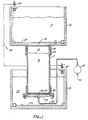
- FIG. 1 is a depiction of one example of an apparatus in accordance with the present invention, shown together with other parts of a full electrophoretic separation system, in a side elevation view in cutaway.
- FIG. 2 depicts the collar, porous plate, dialysis membrane and adjoining parts of the example shown in FIG. 1, in exploded form in side elevation.
- FIG. 3 is a top view of the collar shown in FIG. 2.
- FIG. 4 is a top view of the support plate of FIG. 2.
- FIG. 5 depicts an alternative embodiment to the one shown in FIG. 1, with a modified arrangement of the withdrawal tube, the parts shown in side elevation, in cutaway, and in partially exploded form.
- FIGS. 6a and 6b depict side elevation and top cutaway views, respectively, of the assembled parts of an illustrative embodiment of the present invention, including a clamp structure for securing the parts to the Column.
- the electrophoretic apparatus shown in FIG. 1 includes a tubular gel enclosure 11, an upper buffer chamber 12 and a lower buffer chamber 13.
- the lower buffer chamber 13 rests on a support surface (not shown) such as a laboratory bench top.
- the gel enclosure 11 is held above the lower buffer chamber 13 by any conventional means such as a ring stand clamp (not shown) clamped around the gel enclosure 11 above the level of the lower buffer chamber 13.
- the upper buffer chamber 12 in this embodiment is constructed to be supported by the gel enclosure 11, resting on top of its upper rim.
- the gel shown in this drawing is in two sections, an upper and lower section 14, 15, the two sections differing in gel density, as frequently used in preparative separations.
- the upper buffer chamber 12 has an opening 16, permitting fluid contact and hence electrical contact between the upper buffer solution 17 and the upper gel section 14.
- a gasket 18 such as a rubber O-ring is positioned between the gel enclosure 11 and a sleeve 19 protruding downward from the upper buffer chamber 12 around the opening 16.
- the electric potential between the upper buffer solution 17 and the lower buffer solution 23 (which is in electrical contact with the lower end of the lower gel section 15 through the collar 32 at the base thereof, as explained below) is established by electrodes 24, 25 connected to negative and positive terminals 26, 27 respectively joined by a power source 28.
- FIG. 1 The elements which form the central part of the present invention are shown in FIG. 1 at the lower end of the gel enclosure 11. These elements include the collar 32 sized to fit over the end of the gel enclosure 11, a porous plate 33, which may be fritted glass, porous plastic or the like, a support plate 34, and a dialysis membrane (not visible in this drawing) between the porous plate 33 and the support plate 34.
- An open passage 35 through the center of the support plate 34 leads to transfer tubing 36 through which liquid is drawn by a pump 37 which in turn directs the fluids to a fraction collector (not shown). All elements, including the power source 28, electrodes 24, 25, porous plate 33, dialysis membrane, transfer tubing 36 and pump 37 are conventional equipment such as those commonly used in electrophoretic separations.
- FIG. 2 shows the collar 32, porous plate 33, dialysis membrane 40 and support plate 34 in an exploded view. All parts are circular in this embodiment.
- the outer edge 41 of the dialysis membrane 40 is bent over the edge of a central raised portion of the support plate 34, and held in place by a retaining ring 42, which may be a common rubber O-ring or other similar type of element.
- a retaining ring 42 which may be a common rubber O-ring or other similar type of element.
- the dialysis membrane 40 has an opening in the center to permit passage of the solutes eluting from the Column. Inserted in the open passage 35 is a hollow screw 43 which passes through the opening in the center of the dialysis membrane 40 and a hole 44 in the support plate 34 (visible in FIG.
- the hollow screw 43 offers a small tubular passage for the solutes from the gel 15.
- the end of the screw extends a sufficient length to permit the attachment of flexible tubing.
- the hollow screw 43 in this embodiment serves two functions. The first is to provide a passage between the lower gel section 15 and the exterior of the gel enclosure 11. The second is to seal the opening in the center of the membrane 40, thereby preventing the eluting solutes from leaking into the lower buffer solution 23.
- the hole in the center of the membrane 40 should be made as small as possible while of sufficient diameter to permit insertion therein of the body of the hollow screw 43.
- a leak check may be made as follows.
- the hole in the hollow screw 43 is first plugged with a small rubber stopper.
- the collar 32 is then filled with water and placed on tissue paper, where it is permitted to stand, the tissue paper rendering visible any leakage around the hollow screw 43. Leakages thus detected may be corrected by further tightening of the nut 38, or if necessary, by replacing the membrane 40 with a membrane having a smaller center hole.
- FIG. 3 A top view of the collar 32 appears in FIG. 3.
- the collar 32 forms a cylinder whose inner wall 45 fits over the gel enclosure 11.
- a series of furrows 46 which extend from the upper rim 47 of the collar 32 to the lower face 48 of the bottom flange 49 (see FIG. 2).
- the channels are closed off at the bottom by the support plate 34, but are open to the edges of the porous plate 33, thereby providing feed points spaced around the periphery of the porous plate 33 for entry of the lower buffer solution 23.
- the pump 37 FIG.
- the collar 32 may be secured to the gel enclosure 11 in any of a variety of ways. In some cases, a friction fit will suffice. In others, particularly where a short gel is used, a friction fit will be insufficient and a clamp will be more appropriate. An example of such a clamp is shown in FIGS. 6a and 6b. discussed in detail below. Selection of the optimum securing means for any particular collar or gel enclosure will be readily apparent to those skilled in the art.
- the support plate 34 in the embodiment shown in FIG. 4 is composed of a solid plastic ring and in the middle, a porous plate of somewhat greater thickness than the porous plate 33 in which the solutes eluting from the gel 15 are collected. While other types of support plates may be used, the support plate 34 with a thick porous plate in the middle provides certain advantages, including uniform support over the entire cross section of the apparatus with full and continuous contact between the gel 15 and the lower buffer solution 17. Such support permits the use of a very thin porous plate 33 above the dialysis membrane 40, minimizing the dead volume therein.
- FIG. 5 A second example of an apparatus within the scope of the invention is depicted in FIG. 5.
- a gel enclosure 11 is shown identical to that shown in FIG. 1.
- the system is configured to draw the eluting solutes upward through the Column in a withdrawal tube 54 embedded in the gel, and positioned at approximately the center or axis of the gel enclosure 11.
- This type of arrangement is useful in polyacrylamide less, whereas the arrangement shown in FIGS. 1 and 2 is useful in both polyacrylamide and agarose gels.
- a porous plate 33 identical to that shown in FIGS. 1 and 2 is included.
- the dialysis membrane 55 differs from that of FIGS. 1 and 2 in that it contains no central opening since the solutes are not required to pass through it.
- the design of the collar 56 and support plate 57 are also slightly different from their counterparts in FIG. 2.
- the support plate 57 is flat, with no central raised portion, and the O-ring 58 rests in a groove 59.
- the hollow screw 43 is eliminated entirely.
- the withdrawal tube 54 is of glass or any other inert solid material, preferably transparent, like the gel enclosure 11.
- the withdrawal tube 54 is embedded in and held in place by the gel. This is accomplished by conventional procedures, most conveniently by holding the tube in place by external mechanical means while the gel solution is poured into the gel enclosure 11 on a casting stand with the open end at the base sealed off by either a membrane or a gasket.
- a smooth-surfaced rubber sheet can seal both the gel enclosure 11 and the withdrawal tube 54.
- the membrane or gasket is removed, and the withdrawal tube 54 is secured in place by the gel.
- care is taken to make sure that the lower rims of both the gel enclosure 11 and the withdrawal tube 54 are coplanar, and that the interior of the tube remains open.
- a tube will be selected of sufficient length to extend above the top surface of the gel.
- the components shown in these figures, and likewise suitable for use in other embodiments of the invention, may be made from conventional materials.
- the gel enclosure 11, for example, will generally be made of glass or other materials commonly used for similar purposes. Typical dimensions are approximately 3.8-5.1 cm (1.5-2 inches) outer diameter, 3 mm (1 ⁇ 8 in.) thickness and 10-15.2 cm (4-6 inches) in length.
- the collar may be 2.5-5.1 cm (1-2 inches) in length, and will typically although not necessarily be made of plastic.
- the voltage imposed across the electrodes will typically range from about 10 to about 20 volts per centimeter length.
- the withdrawal tube 54 shown in FIG. 5 may be glass tubing of which the smaller the diameter, the better.
- a typical tube may be of approximately 2 mm outer diameter.
- FIGS. 6a and 6b show a clamp structure incorporated into a collar 56 for securement of the collar 56 to the gel enclosure 11.
- the clamp structure consists of two legs 61, 62 fused to the outer surface of the collar 56 at opposite sides, each leg extending upward above the collar 56.
- Each leg terminates at its upper end in an arc-shaped brace 63, 64, conforming to the curvature of the gel enclosure 11.
- Each brace terminates in a flange 65, 66, 67, and 68, through which a screw 69, 70 is passed, tightening the braces against the gel enclosure 11.
Description
- This invention relates to electrophoretic systems, and in particular to preparative gel electrophoresis.
- As a preparative separation technique, electrophoresis offers the substantial advantage of the ability to separate species which are otherwise very difficult to separate, notably macromolecules and biochemical species in particular. Preparative separations involve the consolidation of solute zones emerging from the column and the transport of these zones to a fraction collector arrangement without permitting them to recombine.
- The need to remove the eluting solute zones without disturbing the separation gel or the electrical potential imposed across it has led to some rather complicated and awkward apparatus constructions. Difficulties encountered with these constructions include irregularities in the fluid flow such as dead volumes and eddies which disturb the zones during transport, inadequate support of the separation gel, and complicated procedures for assembly and disassembly.
- US-A-3579433 (Dahlgren) describes an electrophoresis apparatus in which a cylinder contains a electrophoretic gel which may be held within the cylinder by a partition. The cylinder further contains an elution plate which is provided with a central opening and the opening is connected to a conduit which allows collected material to be removed from the apparatus.
- Koziarz, Köhler and Steck describe in Analytical Biochemistry 86, 78-87 [1978] a system for preparative polyacrylamide gel electrophoresis comprising an instrument having a sample collection assembly for mounting on a gel cylinder in which buffer pumped uniformly upward through a porous plastic disc from a lower tray sweeps the emergency sample into a collection system.
- The present invention overcomes these difficulties by providing apparatus for and method of drawing solutes eluting from a tubular electrophoresis column having the features as delineated in independent claims 1 and 10 respectively, with preferred features as delineated in the dependent claims.
- The porous plate defines a space to receive the eluting solutes, and the dialysis membrane isolates the eluting solutes from the lower buffer solution while permitting electrical contact between the gel and the lower buffer solution. The lower buffer solution is drawn into the region of the porous plate through channels in the inside wall of the collar, and the withdrawal port is arranged to draw lower buffer solution from the periphery of the porous plate to, for example, a central point, thereby consolidating and collecting each individual solute zone prior to withdrawing it from the gel region. Among the various preferred embodiments are those in which the collar is adapted to attach to the Column by a clamp and the channels are furrows along the interior wall of the collar, aligned parallel to the collar axis and regularly spaced. The invention extends to systems where the consolidated solutes are drawn down from the Column, in the same direction as the movement of the zones through the Column, as well as those in which the consolidated zones are drawn upward or back through the Column along the Column axis.
- Further advantages, embodiments and objects of the invention will be apparent from the following description.
- FIG. 1 is a depiction of one example of an apparatus in accordance with the present invention, shown together with other parts of a full electrophoretic separation system, in a side elevation view in cutaway.
- FIG. 2 depicts the collar, porous plate, dialysis membrane and adjoining parts of the example shown in FIG. 1, in exploded form in side elevation.
- FIG. 3 is a top view of the collar shown in FIG. 2.
- FIG. 4 is a top view of the support plate of FIG. 2.
- FIG. 5 depicts an alternative embodiment to the one shown in FIG. 1, with a modified arrangement of the withdrawal tube, the parts shown in side elevation, in cutaway, and in partially exploded form.
- FIGS. 6a and 6b depict side elevation and top cutaway views, respectively, of the assembled parts of an illustrative embodiment of the present invention, including a clamp structure for securing the parts to the Column.
- The electrophoretic apparatus shown in FIG. 1 includes a tubular gel enclosure 11, an
upper buffer chamber 12 and a lower buffer chamber 13. The lower buffer chamber 13 rests on a support surface (not shown) such as a laboratory bench top. The gel enclosure 11 is held above the lower buffer chamber 13 by any conventional means such as a ring stand clamp (not shown) clamped around the gel enclosure 11 above the level of the lower buffer chamber 13. Theupper buffer chamber 12 in this embodiment is constructed to be supported by the gel enclosure 11, resting on top of its upper rim. - The gel shown in this drawing is in two sections, an upper and
lower section upper buffer chamber 12 has anopening 16, permitting fluid contact and hence electrical contact between theupper buffer solution 17 and theupper gel section 14. To prevent leakage of theupper buffer solution 17 around the outside of the gel enclosure 11, agasket 18 such as a rubber O-ring is positioned between the gel enclosure 11 and asleeve 19 protruding downward from theupper buffer chamber 12 around the opening 16. - The electric potential between the
upper buffer solution 17 and the lower buffer solution 23 (which is in electrical contact with the lower end of thelower gel section 15 through thecollar 32 at the base thereof, as explained below) is established byelectrodes positive terminals power source 28. - The elements which form the central part of the present invention are shown in FIG. 1 at the lower end of the gel enclosure 11. These elements include the
collar 32 sized to fit over the end of the gel enclosure 11, aporous plate 33, which may be fritted glass, porous plastic or the like, asupport plate 34, and a dialysis membrane (not visible in this drawing) between theporous plate 33 and thesupport plate 34. Anopen passage 35 through the center of thesupport plate 34 leads to transfertubing 36 through which liquid is drawn by apump 37 which in turn directs the fluids to a fraction collector (not shown). All elements, including thepower source 28,electrodes porous plate 33, dialysis membrane,transfer tubing 36 andpump 37 are conventional equipment such as those commonly used in electrophoretic separations. - FIG. 2 shows the
collar 32,porous plate 33,dialysis membrane 40 andsupport plate 34 in an exploded view. All parts are circular in this embodiment. The outer edge 41 of thedialysis membrane 40 is bent over the edge of a central raised portion of thesupport plate 34, and held in place by aretaining ring 42, which may be a common rubber O-ring or other similar type of element. Although not visible in the drawing, it should further be noted that thedialysis membrane 40 has an opening in the center to permit passage of the solutes eluting from the Column. Inserted in theopen passage 35 is ahollow screw 43 which passes through the opening in the center of thedialysis membrane 40 and ahole 44 in the support plate 34 (visible in FIG. 4), and is secured in place by a nut 38. Thus, through thedialysis membrane 40 and thesupport plate 34, thehollow screw 43 offers a small tubular passage for the solutes from thegel 15. The end of the screw extends a sufficient length to permit the attachment of flexible tubing. - The
hollow screw 43 in this embodiment serves two functions. The first is to provide a passage between thelower gel section 15 and the exterior of the gel enclosure 11. The second is to seal the opening in the center of themembrane 40, thereby preventing the eluting solutes from leaking into thelower buffer solution 23. The hole in the center of themembrane 40 should be made as small as possible while of sufficient diameter to permit insertion therein of the body of thehollow screw 43. Once thehollow screw 43 is inserted and fixed in place by the nut 38, the lower or sloping edge of the screwhead and the slope-shaped opening of thepassage 35 will form a tight seal surrounding the opening in the center of themembrane 40, thereby preventing leakage into thelower buffer solution 23. - In assembling the
collar 32,porous plate 33,dialysis membrane 40 andsupport plate 34 prior to securing these parts to the Column, a leak check may be made as follows. The hole in thehollow screw 43 is first plugged with a small rubber stopper. Thecollar 32 is then filled with water and placed on tissue paper, where it is permitted to stand, the tissue paper rendering visible any leakage around thehollow screw 43. Leakages thus detected may be corrected by further tightening of the nut 38, or if necessary, by replacing themembrane 40 with a membrane having a smaller center hole. - A top view of the
collar 32 appears in FIG. 3. Thecollar 32 forms a cylinder whoseinner wall 45 fits over the gel enclosure 11. Along theinner wall 45 of thecollar 32 are a series offurrows 46 which extend from theupper rim 47 of thecollar 32 to thelower face 48 of the bottom flange 49 (see FIG. 2). When thecollar 32 and the gel enclosure 11 are joined thesefurrows 46 form open channels for passage of thelower buffer solution 23 in which this end of the apparatus is submerged. The channels are closed off at the bottom by thesupport plate 34, but are open to the edges of theporous plate 33, thereby providing feed points spaced around the periphery of theporous plate 33 for entry of thelower buffer solution 23. As the pump 37 (FIG. 1) draws liquid through thehollow screw 43, it in turn draws thelower buffer solution 23 from the lower buffer chamber 13 into thefurrows 46 downward to theporous plate 33, then laterally through theporous plate 33 toward the center and finally out through the small tubular passage of thehollow screw 43, which is open at the top to permit entry of the liquid. The arrangement of thefurrows 46 and the central location of theopen passage 35 causes a lateral sweep of the entire cross section of the bottom end of thegel 15, consolidating the emerging solutes into a narrow stream. The number of furrows or channels is not critical. The number needed will generally depend on the column diameter. In most cases, 6 or more, preferably 12 or more, will be appropriate. In the embodiment shown in FIG. 3, 18 furrows are included. - The
collar 32 may be secured to the gel enclosure 11 in any of a variety of ways. In some cases, a friction fit will suffice. In others, particularly where a short gel is used, a friction fit will be insufficient and a clamp will be more appropriate. An example of such a clamp is shown in FIGS. 6a and 6b. discussed in detail below. Selection of the optimum securing means for any particular collar or gel enclosure will be readily apparent to those skilled in the art. - The
support plate 34 in the embodiment shown in FIG. 4 is composed of a solid plastic ring and in the middle, a porous plate of somewhat greater thickness than theporous plate 33 in which the solutes eluting from thegel 15 are collected. While other types of support plates may be used, thesupport plate 34 with a thick porous plate in the middle provides certain advantages, including uniform support over the entire cross section of the apparatus with full and continuous contact between thegel 15 and thelower buffer solution 17. Such support permits the use of a very thinporous plate 33 above thedialysis membrane 40, minimizing the dead volume therein. - A second example of an apparatus within the scope of the invention is depicted in FIG. 5. Here a gel enclosure 11 is shown identical to that shown in FIG. 1. In this case, however, the system is configured to draw the eluting solutes upward through the Column in a
withdrawal tube 54 embedded in the gel, and positioned at approximately the center or axis of the gel enclosure 11. This type of arrangement is useful in polyacrylamide less, whereas the arrangement shown in FIGS. 1 and 2 is useful in both polyacrylamide and agarose gels. Aporous plate 33 identical to that shown in FIGS. 1 and 2 is included. Thedialysis membrane 55, however, differs from that of FIGS. 1 and 2 in that it contains no central opening since the solutes are not required to pass through it. The design of thecollar 56 andsupport plate 57 are also slightly different from their counterparts in FIG. 2. Thesupport plate 57 is flat, with no central raised portion, and the O-ring 58 rests in agroove 59. Thehollow screw 43 is eliminated entirely. - The
withdrawal tube 54 is of glass or any other inert solid material, preferably transparent, like the gel enclosure 11. Thewithdrawal tube 54 is embedded in and held in place by the gel. This is accomplished by conventional procedures, most conveniently by holding the tube in place by external mechanical means while the gel solution is poured into the gel enclosure 11 on a casting stand with the open end at the base sealed off by either a membrane or a gasket. A smooth-surfaced rubber sheet, for example, can seal both the gel enclosure 11 and thewithdrawal tube 54. - Once the gel solidifies, the membrane or gasket is removed, and the
withdrawal tube 54 is secured in place by the gel. During casting, care is taken to make sure that the lower rims of both the gel enclosure 11 and thewithdrawal tube 54 are coplanar, and that the interior of the tube remains open. A tube will be selected of sufficient length to extend above the top surface of the gel. Once the gel is fully formed, transfer tubing similar to that shown in FIG. 1 (the tubing 36) is attached to the emerging tip (not shown) of thewithdrawal tube 54. The transfer tubing then passes through theupper buffer solution 17 and out of theupper buffer chamber 12 where it feeds thepump 37. - The components shown in these figures, and likewise suitable for use in other embodiments of the invention, may be made from conventional materials. The gel enclosure 11, for example, will generally be made of glass or other materials commonly used for similar purposes. Typical dimensions are approximately 3.8-5.1 cm (1.5-2 inches) outer diameter, 3 mm (⅛ in.) thickness and 10-15.2 cm (4-6 inches) in length. The collar may be 2.5-5.1 cm (1-2 inches) in length, and will typically although not necessarily be made of plastic. The voltage imposed across the electrodes will typically range from about 10 to about 20 volts per centimeter length. The
withdrawal tube 54 shown in FIG. 5 may be glass tubing of which the smaller the diameter, the better. A typical tube may be of approximately 2 mm outer diameter. - FIGS. 6a and 6b show a clamp structure incorporated into a
collar 56 for securement of thecollar 56 to the gel enclosure 11. The clamp structure consists of twolegs collar 56 at opposite sides, each leg extending upward above thecollar 56. Each leg terminates at its upper end in an arc-shapedbrace flange screw - The foregoing is offered primarily for purposes of illustration. It will be readily apparent to those skilled in the art that Variations may be made in the various elements of structure and operation described herein while still falling within the scope of the invention as delineated in the appended claims.
Claims (9)
- Apparatus for drawing solutes eluting from a tubular electrophoresis column (11) having at least one open end and a given cross-section into transfer tubing (36,54), said apparatus having:
a porous plate (33) and a dialysis membrane (40,55), both sized to span said cross-section;
a support plate (34) for securing the porous plate (33) and the dialysis membrane (40); and
a collar (32,56) adapted to receive said open end and to secure said porous plate (33) to said open end and to secure said dialysis membrane (40) between said porous plate (33) and said support plate (34); characterised in that
a plurality of channels (46) in said collar communicate the exterior of said collar with a plurality of loci along the interior wall thereof and being for passage of a buffer solution (23) therethrough, said loci positioned to reside along the periphery of said open end of said electrophoresis column when said collar is joined thereto;
and in that the apparatus also includes means (36,37,54) for drawing from said loci laterally through said porous plate (33) to an opening in said porous plate and out of the apparatus through said transfer tubing (36,54). - Apparatus in accordance with claim 1 further comprising means (61-70) for clamping said collar to said tubular electrophoresis column.
- Apparatus in accordance with claim 1 or claim 2 in which said channels are furrows (46) around the interior wall of said collar (32,56).
- Apparatus in accordance with claim 3 in which said furrows (46) are spaced at substantially regular intervals along said interior wall.
- Apparatus in accordance with any one of the preceding claims in which said withdrawal site (35) is approximately at the centre of said porous plate.
- Apparatus in accordance with any one of the preceding claims in which said dialysis membrane (4) has an opening to permit passage of said solutes therethrough and the fluid drawing means draws fluid through the opening in a direction parallel to the axis of the tubular column in a direction away from the interior of the tubular electrophoresis column.
- Electrophoresis apparatus, including an electrophoresis column (11), having first and second open ends;
wherein apparatus according to any of the preceding claims is connectable to said second open end;
further including upper and lower buffer chambers (12,13) and means (26,27,28) for imposing an electric potential therebetween, said upper buffer chamber (12) being adapted to contain an upper buffer solution (17) and to place said upper buffer solution in fluid contact with a first open end of said column (11), and said lower buffer solution (1) sized to contain the lower buffer solution (23) and to permit immersion of a second open end of said column therein; and
wherein said withdrawal site is a location outside said lower buffer chamber. - Apparatus in accordance with claim 8 in which said collar is shaped to receive said second open end of said electrophoresis column in a friction fit.
- A method of drawing into transfer tubing (36,54) solutes eluting from a tubular electrophoresis column (11) having at least one open end and a given cross section by means of apparatus having:
a porous plate (33) and a dialysis membrane (40,55), both sized to span said cross section;
means (36,37,54) for drawing fluid from the porous plate (33) at a withdrawal site (35) within the periphery thereof;
a collar (32,56) adapted to receive said open end and to secure said porous plate (33) and said dialysis membrane (40) thereto;
a support plate (34) for supporting the porous plate (33) and dialysis membrane (40); characterised in that
buffer solution is passed through a plurality of channels (46) in said collar communicating the exterior of said collar with a plurality of loci along the interior wall thereof; said loci positioned to reside along the periphery of said open end of said tubular electrophoresis column when said collar is joined thereto, the buffer solution entering the porous plate (33) laterally thereof under the action of said means for drawing fluid.
Applications Claiming Priority (2)
| Application Number | Priority Date | Filing Date | Title |
|---|---|---|---|
| US262905 | 1988-10-25 | ||
| US07/262,905 US4877510A (en) | 1988-10-25 | 1988-10-25 | Apparatus for preparative gel electrophoresis |
Publications (3)
| Publication Number | Publication Date |
|---|---|
| EP0366408A2 EP0366408A2 (en) | 1990-05-02 |
| EP0366408A3 EP0366408A3 (en) | 1990-12-19 |
| EP0366408B1 true EP0366408B1 (en) | 1996-03-20 |
Family
ID=22999576
Family Applications (1)
| Application Number | Title | Priority Date | Filing Date |
|---|---|---|---|
| EP89310941A Expired - Lifetime EP0366408B1 (en) | 1988-10-25 | 1989-10-24 | Apparatus for preparative gel electrophoresis |
Country Status (5)
| Country | Link |
|---|---|
| US (1) | US4877510A (en) |
| EP (1) | EP0366408B1 (en) |
| JP (1) | JPH0633477B2 (en) |
| CA (1) | CA1336705C (en) |
| DE (1) | DE68926018T2 (en) |
Families Citing this family (21)
| Publication number | Priority date | Publication date | Assignee | Title |
|---|---|---|---|---|
| US5284559A (en) * | 1992-06-16 | 1994-02-08 | Rhode Island Hospital | Preparative electrophoresis device and method |
| WO1994025144A1 (en) * | 1993-05-05 | 1994-11-10 | Amrad Corporation Limited | Electrophoretic resolution of charged molecules |
| US5332484A (en) * | 1993-08-02 | 1994-07-26 | Hi-Tech Bio-Tech, Inc. | Apparatus and process for the large scale separation and retrieval of proteins from cellular extracts |
| US6319472B1 (en) | 1993-11-01 | 2001-11-20 | Nanogen, Inc. | System including functionally separated regions in electrophoretic system |
| US6375899B1 (en) | 1993-11-01 | 2002-04-23 | Nanogen, Inc. | Electrophoretic buss for transport of charged materials in a multi-chamber system |
| US6331274B1 (en) | 1993-11-01 | 2001-12-18 | Nanogen, Inc. | Advanced active circuits and devices for molecular biological analysis and diagnostics |
| US6225059B1 (en) | 1993-11-01 | 2001-05-01 | Nanogen, Inc. | Advanced active electronic devices including collection electrodes for molecular biological analysis and diagnostics |
| US6129828A (en) * | 1996-09-06 | 2000-10-10 | Nanogen, Inc. | Apparatus and methods for active biological sample preparation |
| US6071394A (en) | 1996-09-06 | 2000-06-06 | Nanogen, Inc. | Channel-less separation of bioparticles on a bioelectronic chip by dielectrophoresis |
| US7857957B2 (en) | 1994-07-07 | 2010-12-28 | Gamida For Life B.V. | Integrated portable biological detection system |
| US6403367B1 (en) | 1994-07-07 | 2002-06-11 | Nanogen, Inc. | Integrated portable biological detection system |
| US5587061A (en) * | 1995-11-28 | 1996-12-24 | Chen; Stephen L. | Device and method for biomolecule purification |
| CA2358480A1 (en) * | 1999-01-12 | 2000-07-20 | Spectrumedix Corporation | Copolymers for capillary gel electrophoresis |
| JP3729729B2 (en) | 2000-11-30 | 2005-12-21 | 日立ソフトウエアエンジニアリング株式会社 | Biopolymer detector and cartridge |
| AU2001250639B2 (en) * | 2001-03-07 | 2007-07-05 | Council Of Scientific And Industrial Research | Gel processing and transfer device |
| US20020127148A1 (en) * | 2001-03-09 | 2002-09-12 | Sanjay Kumar | Gel processing and transfer device |
| US6887362B2 (en) * | 2002-02-06 | 2005-05-03 | Nanogen, Inc. | Dielectrophoretic separation and immunoassay methods on active electronic matrix devices |
| US7025864B2 (en) * | 2003-03-10 | 2006-04-11 | Elchrom Scientific A.G. | Method and apparatus for recovering target molecules from a gel containing said target molecules |
| DE10336540B4 (en) * | 2003-08-05 | 2014-03-13 | Bernd Kastenholz | Method of isolating metal cofactors from biological organic systems using preparative native polyacrylamide continuous gel electrophoresis (PNC-PAGE) |
| US7875162B2 (en) * | 2004-03-26 | 2011-01-25 | Board Of Regents, University Of Houston | Monitored separation device |
| WO2010078601A1 (en) * | 2009-01-05 | 2010-07-08 | The Regents Of The University Of California | High throughput biomolecule separation and analysis |
Family Cites Families (19)
| Publication number | Priority date | Publication date | Assignee | Title |
|---|---|---|---|---|
| US3346479A (en) * | 1964-04-09 | 1967-10-10 | Scientific Industries | Preparative separation by a combination of gel separation and electrophoresis |
| US3375187A (en) * | 1965-05-13 | 1968-03-26 | Buchler Instr Inc | Apparatus for temperature controlled preparative and analytical electrophoresis |
| US3483986A (en) * | 1966-07-25 | 1969-12-16 | Alfred G Wright | Apparatus for performing scientific experiments |
| US3539493A (en) * | 1967-08-31 | 1970-11-10 | Canal Ind Corp | Apparatus for preparative electrophoresis on gel support media |
| US3579433A (en) * | 1968-04-24 | 1971-05-18 | Upjohn Co | Vertical column electrophoresis apparatus |
| US3616454A (en) * | 1969-03-13 | 1971-10-26 | Univ New York | Method of and apparatus for electrophoretic separation in a gel column |
| US3640813A (en) * | 1969-06-09 | 1972-02-08 | Samuel T Nerenberg | Adapter for a macromolecule separation device |
| SE338879B (en) * | 1970-01-15 | 1971-09-20 | Lkb Produkter Ab | |
| NL7115364A (en) * | 1971-11-08 | 1973-05-10 | ||
| DE2221242C3 (en) * | 1972-04-29 | 1974-09-26 | Stephan 8520 Erlangen Nees | Apparatus for preparative electrophoresis and procedures for carrying it out with this apparatus |
| SU434985A1 (en) * | 1972-06-07 | 1974-07-05 | DEVICE FOR PREPARATIVE SEPARATION OF HIGH-MOLECULAR BIOLOGICAL SUBSTANCES | |
| US3795600A (en) * | 1973-03-23 | 1974-03-05 | Instrumentation Specialties Co | Electrophoresis and method apparatus |
| US3980546A (en) * | 1975-06-27 | 1976-09-14 | Caccavo Francis A | Micropreparative electrophoresis apparatus |
| NL182822C (en) * | 1976-05-18 | 1988-05-16 | Roskam Willem Gerrit | PREPARATIVE ELECTROFORESE DEVICE. |
| SU616568A1 (en) * | 1977-01-24 | 1978-07-25 | Специальное Конструкторское Бюро Биофизической Аппаратуры | Apparatus for electro-phoretic separation of substances |
| ATE30270T1 (en) * | 1982-07-23 | 1987-10-15 | Matthias Hediger | DEVICE FOR PREPARATIVE GEL ELECTROPHORESIS, IN PARTICULAR FOR MIXTURE SEPARATION ON A GRADIENT CONTAINING POLYACRYLAMIDE GEL ACID. |
| FR2574311B1 (en) * | 1984-12-11 | 1989-09-15 | Inst Nat Sante Rech Med | IMPROVEMENTS TO PREPARATIVE ELECTROPHORESIS PROCESSES AND APPARATUS |
| US4699706A (en) * | 1986-05-30 | 1987-10-13 | Bio-Rad Laboratories, Inc. | Method and apparatus for extraction of species from electrophoresis media |
| JPH0821679A (en) * | 1994-07-06 | 1996-01-23 | Fuji Electric Co Ltd | Electronic refrigeration type drinking water cooler |
-
1988
- 1988-10-25 US US07/262,905 patent/US4877510A/en not_active Expired - Lifetime
-
1989
- 1989-09-08 CA CA000610793A patent/CA1336705C/en not_active Expired - Lifetime
- 1989-09-27 JP JP1251714A patent/JPH0633477B2/en not_active Expired - Fee Related
- 1989-10-24 DE DE68926018T patent/DE68926018T2/en not_active Expired - Lifetime
- 1989-10-24 EP EP89310941A patent/EP0366408B1/en not_active Expired - Lifetime
Also Published As
| Publication number | Publication date |
|---|---|
| DE68926018D1 (en) | 1996-04-25 |
| EP0366408A3 (en) | 1990-12-19 |
| US4877510A (en) | 1989-10-31 |
| JPH0633477B2 (en) | 1994-05-02 |
| DE68926018T2 (en) | 1996-09-05 |
| CA1336705C (en) | 1995-08-15 |
| EP0366408A2 (en) | 1990-05-02 |
| JPH02122089A (en) | 1990-05-09 |
Similar Documents
| Publication | Publication Date | Title |
|---|---|---|
| EP0366408B1 (en) | Apparatus for preparative gel electrophoresis | |
| US3855111A (en) | Electrophoresis apparatus | |
| US4699706A (en) | Method and apparatus for extraction of species from electrophoresis media | |
| US4608147A (en) | Apparatus for the electro-elution and collecting of electrically charged macromolecules in a trap | |
| US3483986A (en) | Apparatus for performing scientific experiments | |
| US4111785A (en) | Apparatus for preparative electrophoresis | |
| US6136187A (en) | Separation column containing porous matrix and method of packing column | |
| US5284559A (en) | Preparative electrophoresis device and method | |
| US5141621A (en) | Capillary electrophoresis injection device and method | |
| US4964961A (en) | Elution method and device | |
| US4747919A (en) | Apparatus and method for electrophoresis in tubes | |
| US3375187A (en) | Apparatus for temperature controlled preparative and analytical electrophoresis | |
| US3980546A (en) | Micropreparative electrophoresis apparatus | |
| US4588492A (en) | Rotating apparatus for isoelectric focusing | |
| US4181594A (en) | Matrix recovery electrophoresis apparatus | |
| US4710289A (en) | Chromatography precolumn | |
| EP0475533A3 (en) | Method and apparatus for the introduction of a volume of at least one fluid in a tube, in particular suitable for capillary electrophoresis systems and method and apparatus for separating and/or analyzing a fluid material | |
| US3888758A (en) | Apparatus for large scale gel electrophoresis | |
| US4552640A (en) | Electrophoretic apparatus for the quantitative elution of proteins or polypeptides from a gel | |
| US3579433A (en) | Vertical column electrophoresis apparatus | |
| US6139709A (en) | Apparatus for producing electrophoresis gels | |
| EP0070314A1 (en) | Photometric flow cell. | |
| DK556487A (en) | FLOW VOLUME MEASURES FOR LIQUID MEDIA | |
| GB1418922A (en) | Electrophoresis method and apparatus | |
| US4818701A (en) | Apparatus for transferring biological specimens from a gel to a transfer membrane and method |
Legal Events
| Date | Code | Title | Description |
|---|---|---|---|
| PUAI | Public reference made under article 153(3) epc to a published international application that has entered the european phase |
Free format text: ORIGINAL CODE: 0009012 |
|
| AK | Designated contracting states |
Kind code of ref document: A2 Designated state(s): DE FR GB IT |
|
| PUAL | Search report despatched |
Free format text: ORIGINAL CODE: 0009013 |
|
| AK | Designated contracting states |
Kind code of ref document: A3 Designated state(s): DE FR GB IT |
|
| 17P | Request for examination filed |
Effective date: 19901219 |
|
| 17Q | First examination report despatched |
Effective date: 19920522 |
|
| GRAH | Despatch of communication of intention to grant a patent |
Free format text: ORIGINAL CODE: EPIDOS IGRA |
|
| GRAA | (expected) grant |
Free format text: ORIGINAL CODE: 0009210 |
|
| AK | Designated contracting states |
Kind code of ref document: B1 Designated state(s): DE FR GB IT |
|
| REF | Corresponds to: |
Ref document number: 68926018 Country of ref document: DE Date of ref document: 19960425 |
|
| ITF | It: translation for a ep patent filed |
Owner name: MODIANO & ASSOCIATI S.R.L. |
|
| ET | Fr: translation filed | ||
| PLBE | No opposition filed within time limit |
Free format text: ORIGINAL CODE: 0009261 |
|
| STAA | Information on the status of an ep patent application or granted ep patent |
Free format text: STATUS: NO OPPOSITION FILED WITHIN TIME LIMIT |
|
| 26N | No opposition filed | ||
| REG | Reference to a national code |
Ref country code: GB Ref legal event code: IF02 |
|
| PGFP | Annual fee paid to national office [announced via postgrant information from national office to epo] |
Ref country code: DE Payment date: 20081016 Year of fee payment: 20 |
|
| PGFP | Annual fee paid to national office [announced via postgrant information from national office to epo] |
Ref country code: IT Payment date: 20081028 Year of fee payment: 20 |
|
| PGFP | Annual fee paid to national office [announced via postgrant information from national office to epo] |
Ref country code: FR Payment date: 20081014 Year of fee payment: 20 |
|
| PGFP | Annual fee paid to national office [announced via postgrant information from national office to epo] |
Ref country code: GB Payment date: 20081022 Year of fee payment: 20 |
|
| REG | Reference to a national code |
Ref country code: GB Ref legal event code: PE20 Expiry date: 20091023 |
|
| PG25 | Lapsed in a contracting state [announced via postgrant information from national office to epo] |
Ref country code: GB Free format text: LAPSE BECAUSE OF EXPIRATION OF PROTECTION Effective date: 20091023 |