EP0366293A2 - Tri-level method and apparatus for post melting treatment of molten steel - Google Patents
Tri-level method and apparatus for post melting treatment of molten steel Download PDFInfo
- Publication number
- EP0366293A2 EP0366293A2 EP89310263A EP89310263A EP0366293A2 EP 0366293 A2 EP0366293 A2 EP 0366293A2 EP 89310263 A EP89310263 A EP 89310263A EP 89310263 A EP89310263 A EP 89310263A EP 0366293 A2 EP0366293 A2 EP 0366293A2
- Authority
- EP
- European Patent Office
- Prior art keywords
- molten steel
- gasses
- air ejector
- further characterized
- ejector means
- Prior art date
- Legal status (The legal status is an assumption and is not a legal conclusion. Google has not performed a legal analysis and makes no representation as to the accuracy of the status listed.)
- Granted
Links
Images
Classifications
-
- C—CHEMISTRY; METALLURGY
- C21—METALLURGY OF IRON
- C21C—PROCESSING OF PIG-IRON, e.g. REFINING, MANUFACTURE OF WROUGHT-IRON OR STEEL; TREATMENT IN MOLTEN STATE OF FERROUS ALLOYS
- C21C7/00—Treating molten ferrous alloys, e.g. steel, not covered by groups C21C1/00 - C21C5/00
- C21C7/10—Handling in a vacuum
-
- C—CHEMISTRY; METALLURGY
- C21—METALLURGY OF IRON
- C21C—PROCESSING OF PIG-IRON, e.g. REFINING, MANUFACTURE OF WROUGHT-IRON OR STEEL; TREATMENT IN MOLTEN STATE OF FERROUS ALLOYS
- C21C7/00—Treating molten ferrous alloys, e.g. steel, not covered by groups C21C1/00 - C21C5/00
- C21C7/0075—Treating in a ladle furnace, e.g. up-/reheating of molten steel within the ladle
Definitions
- This invention relates to a new method for the post melting treatment of molten steel in all, or nearly all, of the post melting systems in use at this time to lower the oxygen, hydrogen, and, to some extent, the nitrogen content thereof, and carry out the other purposes for which such systems are sued including temperature and chemical homogenzation, continuous casting, piggy backing and other post melting treatment systems in use at this time in a manner which is less capital intensive, easier to operate and simpler in construction and operation than any of the basic systems, and apparatus therefore.
- each of the post melting steel treatment systems in use today is well adapted from a technical standpoint to achieve the results which are demanded of it.
- each system is designed, as it must be, to accommodate the maximum demands which can be envisioned for the system and, as this invention has demonstrated, each such system has inherent deficiencies of a technical or economic nature, or both.
- the conventional vacuum arc degassing system enables a user to lower oxygen and hydrogen contents of molten steel to low levels by the use of a sub-atmospheric pressure (or vacuum) which may be as low as less than 1mm Hg if flake-free hydrogen levels in large sections are desired, an alternating current electric arc which is struck directly between the AC electrodes and the molten steel, and inert gas purging.
- a sub-atmospheric pressure or vacuum
- the vacuum in the 3,501,289 system which system is known as the vacuum arc degassing system
- the vacuum arc degassing system is generated by a plurality of steam jet ejectors and it requires, in the U.S. at least, licensed boiler tenders to operate.
- the inert gas purging is derived from, preferably, one, or at most, two porous bricks, each of which admits from 3-5 cu. ft./min. of purging gas to the molten steel. In some instances a tuyere which produces the same stirring characteristics may be substituted for the purging brick.
- the ladle furnace is essentially a ladle to which a non-airtight arc furnace cover and electrodes have been added together with a gas purging capacity.
- the ladle furnace, or LF is thus capable of heating and purging steel and hence has found application as a holding vessel in a continuous casting system. It is possibly the least expensive of all the post melting systems in that a fully functioning unit may be constructed for only about $250,000.
- the LF however, has no vacuum capacity and hence the now universally recognized benefits of vacuum treatment cannot be attained. Its functions are therefore largely limited to temperature an chemical homogenization and holding operations, all of which are useful in continuous casting system.
- the DH system utilizes a purging gas in the up let of an elevated treatment chamber and a high vacuum in the treatment chamber to cause untreated molten steel in a lower, atmospherically exposed source vessel, such as a ladle, to flow upwardly into the treatment chamber where it is subjected to the action of the vacuum before flowing back to the source vessel through a down leg which discharges from the treatment chamber.
- This system invariably includes a multi-stage steam jet ejector system connected to the treatment chamber to generate the high vacuum therein needed to treat the thin layer of steel flowing from the inlet to the outlet.
- multi-stage steam jet injector systems are effective in generating absolute vacuum levels of 1mm Hg, and even .5mm Hg, they have certain undesirable characteristics.
- First and foremost is the problem of cleaning.
- a heat of steel fresh from a melting unit gives off large quantities of dirt and dust when subjected to a vacuum, and this dirt and dust lowers the efficiency of the steam ejector system.
- Cleaning the ejectors is a disagreeable task which causes the system to be shut down for substantial periods of time at rather frequent intervals -- weekly, or even oftener in high production shops.
- the RH system utilizes a stationary holding vessel and a vertically reciprocable treatment chamber vessel in which a vacuum can be applied.
- a vacuum By manipulation of the relative vertical positions of the two vessels and/or variations in the degree of vacuum applied, a portion of the total melt is drawn into the upper treatment vessel where it may be treated by vacuum and then returned to the lower vessel. After a number of cycles, the total melt will have been treated. If a vacuum of 1mm Hg is applied in the treatment chamber vessel, molten steel in the bottom vessel can be raised up to about 5 feet.
- this system utilizes a steam jet ejector with the characteristics earlier described.
- VAX treatment system A recent proposal has been the so-called VAX treatment system.
- This system though it does not utilize a steam jet ejector system, is capable of substantial inprovement in the post melting phase of steel processing utilizing, in essence, the law of partial pressures to lower the content of undesired gases.
- This system is described in U.S. Patent 4,655,826 which also discloses the use of arc heating, and to which reference is made for a more complete understanding.
- the invention of the first embodiment as disclosed in Figures 1-6 requires a sealed chamber and sealed electrodes as in a conventional vacuum arc degassing system.
- the chamber exhaust connection goes to, for example, one or more small compressed air ejectors and the purging capacity is substantially increased.
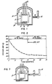
- Figure 1 shows a schematic of the system.
- the system includes a sealed tank, indicated generally at 10, which receives a ladle 11 of molten steel to be treated whereby the space above the metal is sealed at all times from outside ambient atmosphere.
- this basic structure may take the form of a container for the molten steel which receives a hood; the hood and container together defining the isolating environment above the molten steel.
- three alternating current non-consumable electrodes, such as conventional graphite electrodes, are shown at 12 since the heats described herein were performed on vacuum arc degassing system equipment. It should be understood that if side wall wear of the container, usually a ladle, is a concern, a single electrode may be used.
- the single electrode current may be single phase AC, three phase wye connected AC which results in a rippled current, or DC.
- the tank exhausts through a pipe 13 which opens into an air ejector 14 which may have the capacity, for example, when treating an approximately 60 metric ton heat of low alloy steel in a chamber of about 1800 cu. ft. capacity of lowering the pressure in the chamber to the beginning of the glow range of the system, such as, purely by way of example, about 100 mg Hg.
- Three porous purging bricks are indicated at 15, 16, 17 and a source of purging gas, such as argon, is indicated at 18.
- a source of purging gas such as argon
- the rate of purging gas per plug can be varied from 0 to about 8-1/2 cu. ft./min.
- Oxygen is also removed from the bath as a reaction product of the oxygen in the bath and the carbon in the steel or the electrodes.
- the heat of disassociation of alumina may be noted from "Thermochemistry of Steelmaking", Elliot and Gleiser, Vol. I, pages 161, 162 and 277, 1960, Addison-Wesley Pub. Co., Reading, Massachusetts.
- a small diaphragm vacuum pump was connected to the vacuum tank close to the ladle brim to measure an off-gas sample, the pump discharge generating positive pressure and flow to a Horiba Model PIR-2000 CO Analyzer.
- the process of the first embodiment consists essen strictlytially of a combined use of a heating arc, with an air ejector and a higher purge rate when in a conventional vacuum arc degassing cycle. Medium vacuum levels are attained.
- a typical cycle is illustrated in Figure 2.
- the heat trial size was normally 60 metric tons.
- the first 15 minutes were arced using a 50% purge rate which results in the admission of total of 12 SCFM. This arcing period was utilized to enhance oxygen removal and temperature control.
- the second 15 minute portion (no arcing) of the cycle was run at 100% purge rate, 25 SCFM, with the air ejector system pulling down to a deeper vacuum level (around 100mm) to facilitate hydrogen removal. It will be understood that a larger gas input may be required for a larger container and, correspondingly, a smaller input for a smaller container to achieve the desired results.
- the steel should be tapped from the electric furnace at the lowest practicable hydrogen level.
- One way to achieve this result is to generate a vigorous CO boil in the electric furnace shortly prior to tap.
- care should be taken to ensure that there is minimum moisture in furnace alloy additions and slag reagents.
- a fluid slag is desirable to allow maximum gas removal, especially if low-sulfur chemistry is desired.
- a di-calcium silicate slag (Ca2SiO4) with about a 2-1/4 to 1 lime-silica ratio which has a low melting point -1500° C (or 2732° F) may be used to great advantage.
- the oxygen removal in the air ejector cycle varied from a high of 71% to a low of 39% with 56% average.
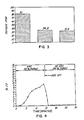
- the average oxygen levels for the air ejector and for comparison, a vacuum arc degassing cycle are shown in Figure 3.
- the air ejector cycle hydrogen removal varied from a high of 36% with 31% average.
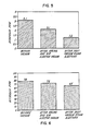
- the average hydrogen levels are shown in Figure 5.
- the air ejector cycle nitrogen removal varied from a high of 20% to a low of 3% with an average removal value of 12%.
- the average nitrogen levels are shown in Figure 6.
- Figure 7 illustrates an alternative embodiment in which an air ejector 14, as above descirbed, or a mechanical pump with a compression ratio of about 5 to 1 is placed in the exhaust line down stream from a blower 19 of the Roots, vane, piston or screw type, or a water ring pump having a compression ratio of about 2 to 1.
- an absolute vacuum in the chamber 10 of about 75mm Hg can be obtained.
- Proper filtration upstream of the pump is, of course, essential to preserve the life of the pump.
- Air ejectors are small and inexpensive and an excellent standby in case of steam failure. Two, 2" air ejectors and one, 3" air ejector were used for the trial heats described above. No. of Air Ejectors Suction Inlet Motive Inlet Motive Fluid (Compressed Air) 1 3" 2" 2050#/Hr. 2 2" 1-1/4" 1025#/Hr. each
- the 2" air ejectors operated in parallel much like hoggers to pull down to 200mm. At this vacuum level, the air supply was cut over to the 3" ejector to continue down to deeper vacuum of around 100mm. Using this operational sequence, the motive fluid requirement was essentially constant at 2050#/Hr. (482 CFM) of 100 psig compressed air. The air was supplied by a 100 HP rotary screw compressor.
- Air ejectors combined with arc and high purge rates area means of processing heats as a stand-alone backup system in the event of a steam supply failure in a conventional steam ejector system.
- the air ejectors used for these trials can be backup for a conventional vacuum arc degassing system.
- the maximum purge rate can be described as the maximum rate the available free board in the container can accommodate without boilover, and it will vary from installation to installation. In effect, it is believed that the equipment generated partial vacuum plus the high purge rate produces a hydrogen partial pressure which equals 1mm Hg absolute.
- the invention can be used as the sole means for achieving the disclosed advantages in Third World countries where a shortage of technical, maintenance, and operations staff exists. Short cycles will be possible if heating, deoxidation, and alloy additions are done simultaneously, thereby eliminating the need to go to 1mm Hg absolute pressure. By using compressed air as the motive fluid, the complexity of the vacuum system is reduced dramatically. A number of items essential to a steam ejector system can be eliminated, including:
- VAD tank and arcing systems remain unchanged in design. If a plant's product mix were to change the deep vacuum was required on all heats, the additional requirements could be easily accommodated. By proper layout of the described system, it will be a simple construction task to add a conventional steam ejector system.
- the system is usable in very cold climates, such as Alberta, where water in conventional steam ejector systems must be heated due to sub-freezing temperatures in the winter months.
- the vacuum tank and arc heating systems are identical to those illustrated in connection with the embodiments of Figures 1-7.
- the tank exhaust port 20 has a 2-way (or 3-way) shut-off valve 21 which functions to connect the interior of the tank 10 to either (a) downstream pipe 22 and thence to the multi-stage steam ejector system indicated generally at 23 and shut off communication with the air ejector cyclone separator-bag house system indicated generally at 24, or (b) by-pass pipe 25 and thence to the air ejector cyclone separator-bag house system 24 and shut off communication with the steam ejector system 23.
- both systems may be installed and operated in conjunction with a common vacuum chamber, and hence both are illustrated.
- the steam ejector system may be used in conjunction with the air ejector system, or without assistance of the air ejector system. It is suffiivelycient to note that the reference numerals S1-S5, inclusive, represent the five stages of the steam ejector system and 1C and 2C represent conventional condensers which discharge into a common dirty water system.
- by-pass pipe 25 admits exhaust gasses with entrained dust and dirt into a cyclone separator indicated generally at 26.
- dirty will be used to mean solid particles, the great bulk of which are of larger than micron size
- dust will be used to mean solid particles the great bulk of which are micron size or smaller.
- a large portion, if not the bulk, of the dirt entrained in the exhaust gasses from the tank are removed in the cyclone separator 26 and may be easily cleaned from time to time as operating conditions permit.
- Line 27 connects the substantially dirt-free gasses leaving the cyclone separator to air ejector AJ-2 via on-off admission valve 28, or to air ejector AJ-2 by on-off admission valve 29.
- Exit line 30 connects air ejector AJ-1 to baghouse line 31, and exit line 32 connects air ejector AJ-2 to baghouse line 31.
- Air compressor 35 driven by motor 36, supplies compressed air (a) via line 37 to entry line 38, which is controlled by on-off valve 39a, to air ejector AJ-1, or (b) to entry line 40, which is controlled by on-off valve 39b to air ejector AJ-2.
- the cooled gases which exit the air ejectors enter baghouse 41 where the bulk of the remaining dust and, in all probability, some dirt is removed in a conventional manner.
- An exhaust fan which discharges to atmosphere is indicated at 42.
- the fan may be employed if there is not enough energy at this stage of the system to push the gasses through the baghouse.
- the fan may, of course, be located upstream of the baghouse if more convenient in a particular installation. By placement downstream as shown, dirt and dust are removed before the gasses reach the fan.
- a typical operating cycle will be substantially as follows.
- shut-off valve 21 operated to isolate the steam ejector system 23 gasses together with entrained dirt and dust will flow via line 25 to cyclone separator 26.
- a typical temperature of the gas entering the cyclone separator may be on the order of about 600°F.
- admission valve 29 in the off position and admission valve 28 in the on position the pressure in lines 25 and 27, and valve 28 may be on the order of about 300 Torr if AJ-1 has approximately a three inch suction inlet and a 2" motive inlet as described above.
- the pressure may be in the range of from about 75 Torr to 150 Torr as determined by the system parameters earlier described, but in any event, above the glow range.
- the temperature in the baghouse inlet line will be on the order of about 130°F, and the pressure will be atmospheric.
- the described embodiment overcomes all of the above problems by installing the air ejector immediately after the vacuum tank and delivering the treated gas stream at its discharge temperature, i.e.: usually less than 225°F, but in any event within the temperature limitation of the baghouse, and atmospheric pressure directly to a conventional baghouse separator.
- the operating advantages of the described system include the elimination of build-up of dirt in the water systems, the use of a baghouse instead of a heat exchange condenser (a baghouse is inherently more efficient than a comparable heat exchange condenser), and great throughput capacity before clean up is required, this latter advantage being particularly important for high throughput shops. Further, the gasses leaving the air ejector are dry.
- the air ejector system is switched off by operation of valve 21, and the steam ejector system 23 activated to subject the steel to the very low vacuum required.
- the steam ejector system 23 activated to subject the steel to the very low vacuum required.
- the operation of the system is advantageous from the practical standpoint as well.
- the inside of a vacuum tank in a vacuum arc degassing system is initially cloudy and visual inspection is of little benefit.
- the atmosphere clears and the operator then immediately knows that operation of the steam ejector system can commence without build-up of dust in said system.
- a super high purge rage in the tank is used in conjunction with the air ejector system, but without arc heating or the steam ejector system.
- a sealed chamber is employed as above-described in connection with the embodiments of Figures 1-7 and Figure 8, but arcs 12 and the entire steam ejector system of Figure 8 may be eliminated or inactivated.
- the molten steel is subjected to a super high inert gas purge rate of about 10 scfm for each purging gas admission location, and the air ejector system is operated to create the intermediate vacuum in the vacuum chamber.
- the rate of gas purge should be substantially as follows: one admission location for up to about 50 tons; two gas admission locations for from about 50 tons up to about 150 tons; and three gas admission locations for heats of about 150 tons or more.
- FIG. 9 illustrates the invention as applied to the RH system.
- a stationary holding or source vessel is indicated at 45 which holds a heat of molten steel 46 whose upper surface 47 is exposed to ambient atmosphere.
- a suitable slag may, of course, be present on the surface of the steel.
- An elevated treatment chamber vessel is indicated generally at 48.
- Vessel 48 has a refractory lined conduit, or first leg, indicated at 49, up which molten steel is drawn when a sub-atmospheric pressure is applied to the interior 50 of treatment vessel 48.
- a gas porous plug (or, if desired, a pipe or tuyere) is shown at 51 connected by line 52 to a regulating and shut off valve 3 which controls the flow of a purging gas which is inert or at least non-deleterious with respect to the composition undergoing treatment. Argon is often used.
- Vessel 48 also includes a second refractory line conduit, or second let, 54 down which molten steel returns to source vessel 45 following treatment in the treatment chamber 48.
- Treatment chamber 48 has an off-take 55 which leads to either ony an air ejector, indicated at 56 or, alternatively, to an off-on-divider valve 57 which connects off-take 55 to either air ejector 56 or a steam ejector system 57.
- the air ejector 56 can be of the same general design as the air ejector earlier described, and assuming a similar size of heat 46, a sub-atmospheric pressure of about 150mm Hg to 50mm Hg can be created in the treatment chamber vessel using air ejector 56 only.
- This vacuum level when applied in conjunction with inert gas admitted to up leg 49 at a rate now well known in the art will set up an excellent circulation of molten steel between the two vessels via legs 49 and 54.
- Application of a vacuum of this magnitude can be applied for an initial period of time which will be sufficient to eliminate the great bulk of the dust and much of the dirt, the exact length of time depending, of course, on the conditions described above. Processing can terminate at this time or, optionally, diverter valve 57 may be operated to close off air ejector 56 and cut in steam ejector 57 if, for example, very low H is desired.
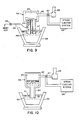
- FIG. 10 illustrates the invention as applied to the DH system.
- a stationary holding or source vessel is indicated at 59 which holds a heat of molten steel 60 whose upper surface 61 is exposed to ambient atmosphere.
- a suitable slag may, of course, be present on the steel.
- An elevated treatment chamber vessel is indicated generally at 62.
- Vessel 62 has a single refractory lined conduit 63 up which molten steel 60 is drawn when a sub-atmospheric pressure is applied to the interior 64 of the treatment vessel 62 and the position of stationary holding vessel 59 and treatment vessel 62 are changed in a manner well known in the art.
- Treatment chamber 62 has an off-take 65 which leads to either only an air ejector, indicated at 56, or, alternatively, to an off-on-diverter valve 57 which connects off- take 65 to either air ejector 56 or a steam ejector system 57.
- the air ejector 56 can be of the same general design as the air ejector earlier described, and assuming a similar size of heat 60, a sub-atmospheric pressure of about 150mm Hg to 50mm Hg can be created in the treatment chamber using air ejector 56 only.
- This vacuum level when applied in conjunction with the reciprocating movement of the treatment vessel with respect to the stationary source vessel 59 will set up up and down cyclical movement of molten steel between the two vessels.
- Application of a vacuum of the magnitude derivable from air ejector means as earlier described for an initial number of cycles will be sufficient to eliminate the great bulk of the dust and much of the dirt, the exact length of time depending, of course, on the conditions described above. Processing can terminate at this time or, optionally, diverter valve 57 may be operated to close off air ejector 56 and cut in steam ejector 57 if, for example, very low H is required.
- the air ejector system can (a) satisfactorily perform the great bulk of the heating, holding and degassing functions at lower cost than the current systems used in the art, such as the multi-station or multi-unit ladle furnace and ladle degasser combination, or the ASEA unit, (b) make existing steam ejector systems easier to operate, and (c) solve cleaning and sludge problems associated with wet systems.
- the air ejector system can enhance the vacuum arc degassing system when used in conjunction therewith as by, for example, reducing clean out from weekly to, possibly yearly.
- the air ejector system of this application :
Landscapes
- Chemical & Material Sciences (AREA)
- Engineering & Computer Science (AREA)
- Materials Engineering (AREA)
- Metallurgy (AREA)
- Organic Chemistry (AREA)
- Waste-Gas Treatment And Other Accessory Devices For Furnaces (AREA)
- Treatment Of Steel In Its Molten State (AREA)
- Coating With Molten Metal (AREA)
- Manufacture And Refinement Of Metals (AREA)
Abstract
isolating molten steel containing undesired gasses from ambient atmosphere whereby a non-atmospheric region is established above the molten steel,
passing a purging agent upwardly through the molten steel from a location beneath the surface which is exposed to the non-atmospheric region,
diverting gasses in the region above the molten steel to air ejector means at a rate sufficient to create a sub-atmospheric pressure in the non-atmospheric region above the molten steel, and
discharging the gasses drawn from the region above the molten steel, and additional gasses which may be added to the air ejector means, from the air ejector means at a temperature which is within the temperature tolerance range of a conventional baghouse.
Description
- This application is a continuation-in-part of application serial number 261,444 filed October 24, 1988.
- This invention relates to a new method for the post melting treatment of molten steel in all, or nearly all, of the post melting systems in use at this time to lower the oxygen, hydrogen, and, to some extent, the nitrogen content thereof, and carry out the other purposes for which such systems are sued including temperature and chemical homogenzation, continuous casting, piggy backing and other post melting treatment systems in use at this time in a manner which is less capital intensive, easier to operate and simpler in construction and operation than any of the basic systems, and apparatus therefore.
- Each of the post melting steel treatment systems in use today is well adapted from a technical standpoint to achieve the results which are demanded of it. However, each system is designed, as it must be, to accommodate the maximum demands which can be envisioned for the system and, as this invention has demonstrated, each such system has inherent deficiencies of a technical or economic nature, or both.
- The conventional vacuum arc degassing system enables a user to lower oxygen and hydrogen contents of molten steel to low levels by the use of a sub-atmospheric pressure (or vacuum) which may be as low as less than 1mm Hg if flake-free hydrogen levels in large sections are desired, an alternating current electric arc which is struck directly between the AC electrodes and the molten steel, and inert gas purging. A typical example can be seen from U.S. Patents 3,236,635 and 3,501,289 with respect to which the present invention is, in part, a further development. Almost invariably, the vacuum in the 3,501,289 system, which system is known as the vacuum arc degassing system, is generated by a plurality of steam jet ejectors and it requires, in the U.S. at least, licensed boiler tenders to operate. Also, in the vast majority of commercial installations, the inert gas purging is derived from, preferably, one, or at most, two porous bricks, each of which admits from 3-5 cu. ft./min. of purging gas to the molten steel. In some instances a tuyere which produces the same stirring characteristics may be substituted for the purging brick.
- Such a system is relatively expensive to build since the steam jet ejector system is relatively expensive. Further, such a system is relatively costly to operate due to the cost of generating steam and operators licensing requirements. It has, however, gained wide acceptance due to the ability to achieve the desired low gas results, as well as many other now well recognized advantages over prior systems including temperature and chemical homogenization, concast applications and others.
- The ladle furnace is essentially a ladle to which a non-airtight arc furnace cover and electrodes have been added together with a gas purging capacity. The ladle furnace, or LF, is thus capable of heating and purging steel and hence has found application as a holding vessel in a continuous casting system. It is possibly the least expensive of all the post melting systems in that a fully functioning unit may be constructed for only about $250,000. The LF, however, has no vacuum capacity and hence the now universally recognized benefits of vacuum treatment cannot be attained. Its functions are therefore largely limited to temperature an chemical homogenization and holding operations, all of which are useful in continuous casting system.
- The DH system utilizes a purging gas in the up let of an elevated treatment chamber and a high vacuum in the treatment chamber to cause untreated molten steel in a lower, atmospherically exposed source vessel, such as a ladle, to flow upwardly into the treatment chamber where it is subjected to the action of the vacuum before flowing back to the source vessel through a down leg which discharges from the treatment chamber. This system invariably includes a multi-stage steam jet ejector system connected to the treatment chamber to generate the high vacuum therein needed to treat the thin layer of steel flowing from the inlet to the outlet.
- Although multi-stage steam jet injector systems are effective in generating absolute vacuum levels of 1mm Hg, and even .5mm Hg, they have certain undesirable characteristics. First and foremost is the problem of cleaning. A heat of steel fresh from a melting unit gives off large quantities of dirt and dust when subjected to a vacuum, and this dirt and dust lowers the efficiency of the steam ejector system. Cleaning the ejectors is a disagreeable task which causes the system to be shut down for substantial periods of time at rather frequent intervals -- weekly, or even oftener in high production shops.
- The following characteristics of steam ejectors may be noted as a background comparison for the advantages attainable with the present invention
- (1) Steam is required for operation. Steam requires a boiler which in turn requires maintenance. The heat energy in the steam is lost, largely, and hence, by comparison as will be apparent hereinafter, steam is an expensive motive fluid.
- (2) A steam ejector system is a wet system, hence steam condensers are required. Since the steam entrains dust and dirt, a sludge is created which is difficult to handle and dispose of and which plugs ejectors, thereby lowering their efficiency.
- (3) A minimum vac of .5mm Hg is attainable, although a more realistically attainable level is 1mm Hg.
- (4) Excellent 0 reduction is attainable, although with special processing such as increased purging rates and/or chemical deoxidation even better 0 reduction is possible
- (5) The lowest possible H reduction of all commercially available systems is attainable.
- (6) A purging gas rate of from 3-5 cfm per approximately each 50 short ton increment of heat size is usual.
- (7) It is quite expensive to purchase and operate because (a) the steam ejectors are quite costly, (b) the boiler is costly, (c) water treatment systems are costly, (d) steam generation costs are approximately 10 times higher than air used as a motive fluid, (e) sludge handling systems are costly as contrasted to dust handling systems, and (f) a large isolating valve is required.
- The combination of a ladle furnace and a ladle degasser, either in the form of two vessels or a single vessel with a vacuum cover which does not contain electrodes and a non-vacuum cover which carries electrodes or other heating means, has also come into use. This system has a relatively high initial cost, particularly as it has been offered by ASEA which includes induction stirring and, of necessity, a stainless steel holding vessel. Again, the vacuum system invariably employed is the steam jet ejector system which has the characteristics mentioned above.
- The RH system utilizes a stationary holding vessel and a vertically reciprocable treatment chamber vessel in which a vacuum can be applied. By manipulation of the relative vertical positions of the two vessels and/or variations in the degree of vacuum applied, a portion of the total melt is drawn into the upper treatment vessel where it may be treated by vacuum and then returned to the lower vessel. After a number of cycles, the total melt will have been treated. If a vacuum of 1mm Hg is applied in the treatment chamber vessel, molten steel in the bottom vessel can be raised up to about 5 feet. Again, this system utilizes a steam jet ejector with the characteristics earlier described.
- A recent proposal has been the so-called VAX treatment system. This system, though it does not utilize a steam jet ejector system, is capable of substantial inprovement in the post melting phase of steel processing utilizing, in essence, the law of partial pressures to lower the content of undesired gases. This system is described in U.S. Patent 4,655,826 which also discloses the use of arc heating, and to which reference is made for a more complete understanding.
- It is highly desirable, however, that the art have access to a system which achieves all, or substantially all, of the advantages of the steam jet ejector system when used in applications requiring very low absolute pressures, and arc heating, but at a lower equipment and operating cost, and is simpler to operate. This need is met by the use of an air ejector applied to any one of the conventional treating systems, either as a sole source of sub-atmospheric pressure, or as a supplement to an existing sub-atmospheric pressure system.
- The invention is illustrated more or less diagrammatically in the following drawing wherein:
- Figure 1 is a schematic view of a first embodiment of the system;
- Figure 2 is a graph plotting vacuum level against time in a heat rum in a physical embodiment of the system of Figure 1;
- Figure 3 is a bar graph showing oxygen removal;
- Figure 4 is a graph plotting CO evolution against time;
- Figure 5 is a bar graph showing hydrogen removal;
- Figure 6 is a bar graph showing nitrogen removal;
- Figure 7 is a diagrammatic sketch of another embodiment of the invention;
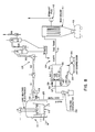
- Figure 8 is a diagrammatic sketch of another embodiment of the invention;
- Figure 9 is a diagrammatic sketch of another embodiment of the invention, this time is applied to the DH process; and
- Figure 10 is a diagrammatic sketch of another embodiment of the invention as applied to the RH process.
- Like reference numerals will refer to like parts from Figure to Figure in the drawing.
- The invention of the first embodiment as disclosed in Figures 1-6 requires a sealed chamber and sealed electrodes as in a conventional vacuum arc degassing system. However, instead of using a large steam ejector system with barometric condensers, cooling tower, circulating pumps, and hot well, the chamber exhaust connection goes to, for example, one or more small compressed air ejectors and the purging capacity is substantially increased. Figure 1 shows a schematic of the system.
- The system includes a sealed tank, indicated generally at 10, which receives a
ladle 11 of molten steel to be treated whereby the space above the metal is sealed at all times from outside ambient atmosphere. It will be understood that this basic structure may take the form of a container for the molten steel which receives a hood; the hood and container together defining the isolating environment above the molten steel. In this instance, three alternating current non-consumable electrodes, such as conventional graphite electrodes, are shown at 12 since the heats described herein were performed on vacuum arc degassing system equipment. It should be understood that if side wall wear of the container, usually a ladle, is a concern, a single electrode may be used. The single electrode current may be single phase AC, three phase wye connected AC which results in a rippled current, or DC. The tank exhausts through apipe 13 which opens into anair ejector 14 which may have the capacity, for example, when treating an approximately 60 metric ton heat of low alloy steel in a chamber of about 1800 cu. ft. capacity of lowering the pressure in the chamber to the beginning of the glow range of the system, such as, purely by way of example, about 100 mg Hg. - It will be understood that a definite vacuum level for the onset of glow cannot be given because glow depends on factors which vary from installation to installation such as vacuum level, voltage, amperage, gas composition in the sealed chamber, electrode temperature, dust in the environment above the molten steel, and others. In the illustrated example, 14" graphite electrodes operating at about 230 volts and 18,000 amps were employed, and glow was observed to begin generally in the 150mm Hg to 80mm Hg range.
- Three porous purging bricks are indicated at 15, 16, 17 and a source of purging gas, such as argon, is indicated at 18. By suitable valving, the rate of purging gas per plug can be varied from 0 to about 8-1/2 cu. ft./min.
- In several trial heats three purge plugs were used in the ladle instead of the normal two plugs which resulted in high purge rates up to a combined total of 25 SCFM. This is approximately five times the normal purge rate used today.
- The process takes full advantage of the "dynamic window" under the arcs to enhance gas removal, said window being formed by the power of the arcs which exposes bare metal to the arcs and facilitates the disassociation of alumina into aluminum and oxygen, the oxygen in turn combining with carbon to form CO in accordance with the following equation:
Al₂O₃(s)+3C = 2 Al + 3CO(g) - Oxygen is also removed from the bath as a reaction product of the oxygen in the bath and the carbon in the steel or the electrodes. The heat of disassociation of alumina may be noted from "Thermochemistry of Steelmaking", Elliot and Gleiser, Vol. I, pages 161, 162 and 277, 1960, Addison-Wesley Pub. Co., Reading, Massachusetts.
- It will be noted that with high purging rates as described herein plus air ejector means placed in series, a low absolute pressure can be attained, and hence a high degree of hydrogen removal is made possible, all without the equipment and operating expense of steam jet ejectors.
- A small diaphragm vacuum pump was connected to the vacuum tank close to the ladle brim to measure an off-gas sample, the pump discharge generating positive pressure and flow to a Horiba Model PIR-2000 CO Analyzer.
- The process of the first embodiment consists essentially of a combined use of a heating arc, with an air ejector and a higher purge rate when in a conventional vacuum arc degassing cycle. Medium vacuum levels are attained. A typical cycle is illustrated in Figure 2.
- The heat trial size was normally 60 metric tons. The first 15 minutes were arced using a 50% purge rate which results in the admission of total of 12 SCFM. This arcing period was utilized to enhance oxygen removal and temperature control. The second 15 minute portion (no arcing) of the cycle was run at 100% purge rate, 25 SCFM, with the air ejector system pulling down to a deeper vacuum level (around 100mm) to facilitate hydrogen removal. It will be understood that a larger gas input may be required for a larger container and, correspondingly, a smaller input for a smaller container to achieve the desired results.
- For best results, the steel should be tapped from the electric furnace at the lowest practicable hydrogen level. One way to achieve this result is to generate a vigorous CO boil in the electric furnace shortly prior to tap. In addition, care should be taken to ensure that there is minimum moisture in furnace alloy additions and slag reagents.
- An average hydrogen level of the molten steel going into the vacuum tank of about 3.2 ppm maximum is attainable and desirable.
- A fluid slag is desirable to allow maximum gas removal, especially if low-sulfur chemistry is desired. A di-calcium silicate slag (Ca₂SiO₄) with about a 2-1/4 to 1 lime-silica ratio which has a low melting point -1500° C (or 2732° F) may be used to great advantage.
- Six trial heats were evaluated representing various compositions. Standard grades AISI 1035 and 4340 were treated as well as specialty die steel and P-20 all as illustrated in Table I.
TABLE I C Mn P S Si Ni Cr Mo V Al FX .50/.58 .75/.95 .010 .030 .15/.35 .85/1.05 .85/1.15 .33/.43 .05 .015/.025 P20 .30/.35 .70/.90 .010 .020 .35/.55 - 1.55/1.85 .40/.50 - .015/.025 - The results obtained utilizing the air ejector system are illustrated in Table II. In this instance, all heats were subsequently subjected to the normal deep vacuum cycle of less than 1mm Hg since the product specifications required flake-free steel, and thus this extra precaution was deemed prudent in view of the lack of extended experience. Gas analyses after the deep vacuum cycle are included.
TABLE II AIR EJECTOR HEATS Heat # Grade H N O Purge Plugs Arc Time Medium Vac Time Total Time Air Ejector Best Vac MM Temp Start °F Temp Finish Total Ft.³ Ar. Highest Purge Rate Ft.³/Min. 264468 FX 2.5 82 64 BV 2.0 72 27 AA 3 8.5 21.5 30 193 3040 2870 750 25 1.2 63 20 AV 165135 1035 2.6 59 63 BV 1.9 74 39 AA 3 15 15 30 147 2990 2920 688 23 0.9 64 36 AV 264685 4340 3.2 66 105 BV 2.0 64 30 AA 2 17.5 12.5 30 92 2975 2840 284 10 1.4 61 44 AV 165128 MD 3.1 101 76 BV 2.2 89 36 AA 2 11.5 20 31.5 103 3035 2910 443 10 1.9 81 24 AV 264695 FX 4.2 81 89 BV 2.7 70 35 AA 2 15 15 30 100 2960 2885 338 11 0.8 64 AV 165139 FX 3.2 79 89 BV 2.1 63 39 AA 3 15 30 30 86 2990 2930 200 7 1.2 55 55 AV BV = Before Arcing and Air Ejector AA = After Arcing and Air Ejector @ 100mm Hg Abs. AV = After Deep Vacuum Treatment @ 1mm Hg Abs. - Sample pins of the molten steel were used for gas analysis. The pins were taken with an evacuated glass tube drawn from a spoon sample which are immediately quenched in ice water. Oxygen and nitrogen were determined on a LECO TC30 special instrument, and hydrogen was determined on an Itac 01 instrument.
- The oxygen removal in the air ejector cycle varied from a high of 71% to a low of 39% with 56% average. The average oxygen levels for the air ejector and for comparison, a vacuum arc degassing cycle are shown in Figure 3.
- The results show removal of an average of 47ppm of oxygen using the air ejectors. An additional 3ppm of oxygen was removed through the deep vacuum cycle. The greatest oxygen removal with the air ejectors was 75ppm with the least being 24.5ppm.
- The large amount of oxygen removal during the air ejector cycle can be attributed to the combination of the arcs with high purge rate in the beginning of the cycle. Referring to Figure 4, it will be noted that the CO present in the vacuum chamber goes to a high of 10% while arcing and then decreases rapidly when the arc is extinguished. If flake-free product is not required (i.e.: 2.2ppm H₂ max.), and thus only oxygen was of concern, a shortened cycle of 15 minutes using a high purge rate and heating will accomplish the objective.
- The air ejector cycle hydrogen removal varied from a high of 36% with 31% average. The average hydrogen levels are shown in Figure 5.
- An average of 1ppm of hydrogen was removed using the air ejectors. If the steel, at the time of tapping from the melting unit, has a sufficiently low hydrogen content, say 3.2ppm or less, it is possible to reach flake-free hydrogen levels after the air ejector process along. An additional .9ppm hydrogen was removed through a multi-stage steam ejector deep vacuum cycle. The greatest hydrogen removal using air ejectors was 1.5ppm -- with the least being .5ppm.
- The air ejector cycle nitrogen removal varied from a high of 20% to a low of 3% with an average removal value of 12%. The average nitrogen levels are shown in Figure 6.
- Figure 7 illustrates an alternative embodiment in which an
air ejector 14, as above descirbed, or a mechanical pump with a compression ratio of about 5 to 1 is placed in the exhaust line down stream from ablower 19 of the Roots, vane, piston or screw type, or a water ring pump having a compression ratio of about 2 to 1. As a result, an absolute vacuum in thechamber 10 of about 75mm Hg can be obtained. Proper filtration upstream of the pump is, of course, essential to preserve the life of the pump. - It will be noted that with high purging rates as described herein plus air ejector means placed in series, a low absolute pressure can be attained, and hence a great degree of hydrogen removal is made possible, all without the equipment and operating expense of steam jet ejectors.
- Air ejectors are small and inexpensive and an excellent standby in case of steam failure. Two, 2" air ejectors and one, 3" air ejector were used for the trial heats described above.
No. of Air Ejectors Suction Inlet Motive Inlet Motive Fluid (Compressed Air) 1 3" 2" 2050#/Hr. 2 2" 1-1/4" 1025#/Hr. each - The 2" air ejectors operated in parallel much like hoggers to pull down to 200mm. At this vacuum level, the air supply was cut over to the 3" ejector to continue down to deeper vacuum of around 100mm. Using this operational sequence, the motive fluid requirement was essentially constant at 2050#/Hr. (482 CFM) of 100 psig compressed air. The air was supplied by a 100 HP rotary screw compressor.
- Air ejectors combined with arc and high purge rates area means of processing heats as a stand-alone backup system in the event of a steam supply failure in a conventional steam ejector system. The air ejectors used for these trials can be backup for a conventional vacuum arc degassing system.
- The maximum purge rate can be described as the maximum rate the available free board in the container can accommodate without boilover, and it will vary from installation to installation. In effect, it is believed that the equipment generated partial vacuum plus the high purge rate produces a hydrogen partial pressure which equals 1mm Hg absolute.
- The invention can be used as the sole means for achieving the disclosed advantages in Third World countries where a shortage of technical, maintenance, and operations staff exists. Short cycles will be possible if heating, deoxidation, and alloy additions are done simultaneously, thereby eliminating the need to go to 1mm Hg absolute pressure. By using compressed air as the motive fluid, the complexity of the vacuum system is reduced dramatically. A number of items essential to a steam ejector system can be eliminated, including:
- 1) Large ejectors, condensers, and piping
- 2) Boiler and feed water treatment
- 3) Large cooling tower.
- Another advantage is that the VAD tank and arcing systems remain unchanged in design. If a plant's product mix were to change the deep vacuum was required on all heats, the additional requirements could be easily accommodated. By proper layout of the described system, it will be a simple construction task to add a conventional steam ejector system.
- Further, the system is usable in very cold climates, such as Alberta, where water in conventional steam ejector systems must be heated due to sub-freezing temperatures in the winter months.
- In the embodiment of Figure 8 the vacuum tank and arc heating systems are identical to those illustrated in connection with the embodiments of Figures 1-7. In this system, however, the
tank exhaust port 20 has a 2-way (or 3-way) shut-offvalve 21 which functions to connect the interior of thetank 10 to either (a)downstream pipe 22 and thence to the multi-stage steam ejector system indicated generally at 23 and shut off communication with the air ejector cyclone separator-bag house system indicated generally at 24, or (b) by-pass pipe 25 and thence to the air ejector cyclone separator-bag house system 24 and shut off communication with thesteam ejector system 23. It will be understood that both systems may be installed and operated in conjunction with a common vacuum chamber, and hence both are illustrated. The following description of the air ejector system should be read with the understanding that if a final, very low vacuum is required, as when flake-free steel for critical applications is desired, the steam ejector system may be used in conjunction with the air ejector system, or without assistance of the air ejector system. It is sufficient to note that the reference numerals S1-S5, inclusive, represent the five stages of the steam ejector system and 1C and 2C represent conventional condensers which discharge into a common dirty water system. - Referring now to the air ejector system, it will be seen that by-
pass pipe 25 admits exhaust gasses with entrained dust and dirt into a cyclone separator indicated generally at 26. In this connection, and for purposes of this specification, the term "dirt" will be used to mean solid particles, the great bulk of which are of larger than micron size, and the term "dust" will be used to mean solid particles the great bulk of which are micron size or smaller. It is believed that there is, as of today, no universally accepted definition of the non-gaseous components removed from the tank during operation, though it is believed the aforesaid definitions are reasonably descriptive and impart, meaningful concepts to those skilled in the art. - A large portion, if not the bulk, of the dirt entrained in the exhaust gasses from the tank are removed in the
cyclone separator 26 and may be easily cleaned from time to time as operating conditions permit. -
Line 27 connects the substantially dirt-free gasses leaving the cyclone separator to air ejector AJ-2 via on-offadmission valve 28, or to air ejector AJ-2 by on-offadmission valve 29.Exit line 30 connects air ejector AJ-1 tobaghouse line 31, andexit line 32 connects air ejector AJ-2 tobaghouse line 31. -
Air compressor 35, driven bymotor 36, supplies compressed air (a) vialine 37 toentry line 38, which is controlled by on-off valve 39a, to air ejector AJ-1, or (b) toentry line 40, which is controlled by on-off valve 39b to air ejector AJ-2. - The cooled gases which exit the air ejectors enter
baghouse 41 where the bulk of the remaining dust and, in all probability, some dirt is removed in a conventional manner. An exhaust fan which discharges to atmosphere is indicated at 42. The fan may be employed if there is not enough energy at this stage of the system to push the gasses through the baghouse. The fan may, of course, be located upstream of the baghouse if more convenient in a particular installation. By placement downstream as shown, dirt and dust are removed before the gasses reach the fan. - A typical operating cycle will be substantially as follows.
- With shut-off
valve 21 operated to isolate thesteam ejector system 23, gasses together with entrained dirt and dust will flow vialine 25 tocyclone separator 26. A typical temperature of the gas entering the cyclone separator may be on the order of about 600°F. Withadmission valve 29 in the off position andadmission valve 28 in the on position, the pressure inlines valve 28 may be on the order of about 300 Torr if AJ-1 has approximately a three inch suction inlet and a 2" motive inlet as described above. If, after reaching this absolute pressure level, AJ-1 is shut off, as by closure ofvalve 28, and AJ- is activated, as by the opening ofvalve 29, the pressure may be in the range of from about 75 Torr to 150 Torr as determined by the system parameters earlier described, but in any event, above the glow range. - In either event, the temperature in the baghouse inlet line will be on the order of about 130°F, and the pressure will be atmospheric.
- In the baghouse the great bulk of the remaining dirt, if any, and dust will be separated from the gasses in which they are entrained, and substantially dirt and dust free gasses will be discharged to the atmosphere. The dirt and dust separated in the baghouse is cleaned out periodically by clean-out
mechanism 43 which is well known in the art. - The advantages of the illustrated and described embodiment can be appreciated from the following.
- All vacuum arc degassing systems have a common dirt and dust problems; that is, the dirt and dust leaving the vacuum chamber builds up in the ejector stages, and particularly the booster stages, and also accumulates in the heat wells, settling basins and other locations.
- Drop out pockets and clean out doors have been installed to collect and remove the dirt and dust, but these expedients have yielded minimal results. High pressure water sprays, either manual or built-in have been used and are effective in removing the build-up in the throats of the ejectors, but these do not remedy the problem because the ejectors run at less than optimum efficiency prior to cleanout, and dirt and dust accumulates in other undesirable locations in the system. Dirt separators using metal turnings have been tried with some success but they are a nuisance to maintain. An expedient which would naturally occur to one skilled in the art would be to by pass the booster ejector stages and deliver the gasses to one of the direct contact condensers or to a water ring pump. Such expedients would relieve the build-up in the booster ejectors but would not correct the build-up in the water systems. Some shops are very concerned due to local factors about dirt build-up in the water system and strive at all times to maintain the water system as clean as possible.
- The possibility of directing the exhaust gasses directly from the tank to a conventional baghouse operating under vacuum and then to the final stage of the vacuum system is not feasible because the acceptable working temperature of baghouses, as currently available on a commercial seals, are well below the temperature of the exhaust gasses. For example, the maximum acceptable limit of baghouses is currently only about 225°F, and the temperature of the exhaust gasses is on the order of about 600°F. Conventional means to cool the stream would require mixing tempering (i.e.: diluting) air with the hot exhaust gasses to reduce the temperature to the baghouse temperature limitation. However, tempering air could not be used in the described system since the volume would require excessively large pumping capacities. Alternately, shell and tube heat exchangers could be used ahead of the baghouse, but the dirt and dust load remaining in the exhaust gasses after leaving the cyclone separator would plug up the heat exchangers.
- The described embodiment overcomes all of the above problems by installing the air ejector immediately after the vacuum tank and delivering the treated gas stream at its discharge temperature, i.e.: usually less than 225°F, but in any event within the temperature limitation of the baghouse, and atmospheric pressure directly to a conventional baghouse separator.
- From test results on a 60 ton system using two air ejectors as above described, the following will be noted:
Motive air = 225 scfm = 450 scfm pumped gas = 200 scfm TOTAL 650 scfm Therefore, actual gas delivered at 130°F = 724 acfm - The operating advantages of the described system include the elimination of build-up of dirt in the water systems, the use of a baghouse instead of a heat exchange condenser (a baghouse is inherently more efficient than a comparable heat exchange condenser), and great throughput capacity before clean up is required, this latter advantage being particularly important for high throughput shops. Further, the gasses leaving the air ejector are dry.
- A great advantage of the above described system in conjunction with steels which must be melted to a low sulfur content, such as .010 or below, is that such steels can be made with no excessive degradation of the steam ejector system. Low sulphur contents require final hydrogen contents of even lower than the normally accepted standard of 2.2ppm, and, as is well known, the attainment of such low sulphur with flake-free properties is a difficult task for the steelmaker. However, the system illustrated in Figure 8 provides the ideal combination of operating parameters to achieve the desired result. Specifically, the
air ejector system 24 of Figure 8 would be activated until the bulk of the dirt and dust has been removed. Once this point is reached, the air ejector system is switched off by operation ofvalve 21, and thesteam ejector system 23 activated to subject the steel to the very low vacuum required. As a result, little or no dirt or dust will collect in the steam ejector. The operation of the system is advantageous from the practical standpoint as well. As is well known, the inside of a vacuum tank in a vacuum arc degassing system is initially cloudy and visual inspection is of little benefit. However, as soon as the atmosphere becomes too rare to support the dirt, the atmosphere clears and the operator then immediately knows that operation of the steam ejector system can commence without build-up of dust in said system. - The economic advantage of the described system, even assuming a bag house must be purchased, over the best alternatives which can be visualized (i.e.: a water ring and separator pump operating in conjunction with an exchange heat condenser) is on the order of about $44,000 (compressor - $30,000; air ejectors (2) - $4,000; baghouse - $10,000) vs. $80,000 (water ring pump - $60,000; exchange heat condenser - $20,000).
- In a further embodiment utilizing the air ejector system illustrated in Figure 8, a super high purge rage in the tank is used in conjunction with the air ejector system, but without arc heating or the steam ejector system.
- Specifically, a sealed chamber is employed as above-described in connection with the embodiments of Figures 1-7 and Figure 8, but arcs 12 and the entire steam ejector system of Figure 8 may be eliminated or inactivated. The molten steel is subjected to a super high inert gas purge rate of about 10 scfm for each purging gas admission location, and the air ejector system is operated to create the intermediate vacuum in the vacuum chamber. Preferably, and using a 60 short ton heat in a conventional ladle as a reference point, the rate of gas purge should be substantially as follows: one admission location for up to about 50 tons; two gas admission locations for from about 50 tons up to about 150 tons; and three gas admission locations for heats of about 150 tons or more. Those skilled in the art will recognize the above described purging rates as extremely high. One inevitable result will be a very high boil. In a single gas emission location it is contemplated that such a high purge rate used in conjunction with the air ejector system of this invention will require on the order of about one meter of freeboard, and a system using two or more gas admission locations will require about 1-1/2 meters of freeboard. The freeboard, and not the temperature drop, will be the limiting factor of the process since the results derived, especially if non-flake-free steel is required, will be accomplished quickly enough so that deleterious superheat is not required. The violent boil also speeds up the slag-metal reactions and, further, shortens the cycle time. For low alloy steel this can mean a tapping temperature of anywhere in the 2,850°F to 2,950°F range.
- Figure 9 illustrates the invention as applied to the RH system. A stationary holding or source vessel is indicated at 45 which holds a heat of
molten steel 46 whoseupper surface 47 is exposed to ambient atmosphere. A suitable slag may, of course, be present on the surface of the steel. An elevated treatment chamber vessel is indicated generally at 48.Vessel 48 has a refractory lined conduit, or first leg, indicated at 49, up which molten steel is drawn when a sub-atmospheric pressure is applied to the interior 50 oftreatment vessel 48. A gas porous plug (or, if desired, a pipe or tuyere) is shown at 51 connected byline 52 to a regulating and shut offvalve 3 which controls the flow of a purging gas which is inert or at least non-deleterious with respect to the composition undergoing treatment. Argon is often used.Vessel 48 also includes a second refractory line conduit, or second let, 54 down which molten steel returns to sourcevessel 45 following treatment in thetreatment chamber 48. -
Treatment chamber 48 has an off-take 55 which leads to either ony an air ejector, indicated at 56 or, alternatively, to an off-on-divider valve 57 which connects off-take 55 to eitherair ejector 56 or asteam ejector system 57. - Since the
air ejector 56 can be of the same general design as the air ejector earlier described, and assuming a similar size ofheat 46, a sub-atmospheric pressure of about 150mm Hg to 50mm Hg can be created in the treatment chamber vessel usingair ejector 56 only. This vacuum level when applied in conjunction with inert gas admitted to upleg 49 at a rate now well known in the art will set up an excellent circulation of molten steel between the two vessels vialegs 49 and 54. Application of a vacuum of this magnitude can be applied for an initial period of time which will be sufficient to eliminate the great bulk of the dust and much of the dirt, the exact length of time depending, of course, on the conditions described above. Processing can terminate at this time or, optionally,diverter valve 57 may be operated to close offair ejector 56 and cut insteam ejector 57 if, for example, very low H is desired. - Figure 10 illustrates the invention as applied to the DH system. A stationary holding or source vessel is indicated at 59 which holds a heat of
molten steel 60 whoseupper surface 61 is exposed to ambient atmosphere. A suitable slag may, of course, be present on the steel. An elevated treatment chamber vessel is indicated generally at 62.Vessel 62 has a single refractory linedconduit 63 up whichmolten steel 60 is drawn when a sub-atmospheric pressure is applied to the interior 64 of thetreatment vessel 62 and the position ofstationary holding vessel 59 andtreatment vessel 62 are changed in a manner well known in the art. -
Treatment chamber 62 has an off-take 65 which leads to either only an air ejector, indicated at 56, or, alternatively, to an off-on-diverter valve 57 which connects off- take 65 to eitherair ejector 56 or asteam ejector system 57. - Since the
air ejector 56 can be of the same general design as the air ejector earlier described, and assuming a similar size ofheat 60, a sub-atmospheric pressure of about 150mm Hg to 50mm Hg can be created in the treatment chamber usingair ejector 56 only. This vacuum level when applied in conjunction with the reciprocating movement of the treatment vessel with respect to thestationary source vessel 59 will set up up and down cyclical movement of molten steel between the two vessels. Application of a vacuum of the magnitude derivable from air ejector means as earlier described for an initial number of cycles will be sufficient to eliminate the great bulk of the dust and much of the dirt, the exact length of time depending, of course, on the conditions described above. Processing can terminate at this time or, optionally,diverter valve 57 may be operated to close offair ejector 56 and cut insteam ejector 57 if, for example, very low H is required. - From the above it will be seen that the air ejector system can (a) satisfactorily perform the great bulk of the heating, holding and degassing functions at lower cost than the current systems used in the art, such as the multi-station or multi-unit ladle furnace and ladle degasser combination, or the ASEA unit, (b) make existing steam ejector systems easier to operate, and (c) solve cleaning and sludge problems associated with wet systems. Indeed, the air ejector system can enhance the vacuum arc degassing system when used in conjunction therewith as by, for example, reducing clean out from weekly to, possibly yearly. In summary, the air ejector system of this application:
- 1) solves the cleaning problems associated with ladle degassers, the ASEA system or, indeed, any steam ejector system in which a high purge rate can be satisfactorily substituted for a very low vacuum;
- 2) functions as pre-cleaner for vacuum arc degassing systems, such as the DH and the RH systems;
- 3) permits operation of vacuum processing plants in Arctic regions; and
- 4) provides an effective treating method in Third World locations where clean air and steam generation and handling are a problem.
- A summary of the practical characteristics of the air ejector system includes the following:
- 1) compressed air is employed thereby eliminating a boiler;
- 2) it is a dry system and therefore the inevitable dust build up is easy to collect;
- 3) a minimum vacuum level of about 50mm Hg can be attained which is adequate for many applications;
- 4) final 0 values can be on a par with a vacuum arc system or, indeed, any system using a deep vacuum;
- 5) final H values may be only 1/3 to 1/2 ppm greater than a vacuum arc degassing or other deep vacuum system;
- 6) very high purge rates are required;
- 7) it is significantly less expensive than any of the existing conventional systems;
- 8) the cost of fume control can be no greater than the cost of forming vacuum tight electrodes;
- 9) it operates independently of ambient temperature thereby making operation in Arctic regions feasible; and
- 10) it is simpler to operate and maintain that existing systems.
- Although a preferred embodiment and alternative embodiments of the invention have been illustrated and described, it will be apparent that modifications may be made within the spirit and scope of the invention. Accordingly, the scope of the invention should be limited solely by the scope of the hereinafter appended claims when interpreted in view of the pertiment prior art.
Claims (20)
isolating molten steel containing undesired gasses from ambient atmosphere whereby a non-atmospheric region is established above the molten steel,
passing a purging agent upwardly through the molten steel from a location beneath the surface which is exposed to the non-atmospheric region,
diverting gasses in the region above the molten steel to air ejector means at a rate sufficient to create a sub-atmospheric pressure in the non-atmospheric region above the molten steel, and
discharging the gasses drawn from the region above the molten steel, and additional gasses which may be added to the air ejector means, from the air ejector means at a temperature which is within the temperature tolerance range of a conventional baghouse.
the purging agent is passed upwardly through the molten steel at least partially during the time the gasses in the region above the molten steel are diverted by said air ejector means.
the gasses diverted from the region above the molten steel, together with solids entrained therein, are passed through a cyclone separator whereby a portion of the entrained solids are removed.
the gasses diverted from the region above the molten steel are passed through the cyclone separator prior to their passage through the air ejector means.
the gasses discharged from the air ejector means are at a temperature no greater than about 225° and at a pressure which is substantially atmospheric.
the gasses discharged from the air ejector means are passed through a baghouse whereby at least a portion of solids entrained in said gasses as said gasses leave the air ejector means are removed in said baghouses.
a pressure differential across the baghouse is created by means in the flow path of the gasses which is downstream from the air ejector means.
a pressure differential across the baghouse is created by means in the flow path of the gasses which is downstream from the baghouse.
the molten steel is subjected to a heating arc.
the heating arc is derived from alternating current which is applied directly to the surface of the molten steel from electrode means.
the electrode means are selected from the group consisting essentially of three carbon-type electrodes or a single DC electrode.
the purging agent is passed upwardly through the molten steel during at least a portion of the time the gasses in the region above the molten steel are diverted from said region by said air ejector means.
the rate of gas purge is no less than about 10 scfm per gas purge admission point.
the number of gas purge admission locations vary with the quantity of molten steel being treated in the ratios of one gas admission location for up to about 50 short tons of steel, two gas admission locations for from about 50 to about 150 short tons, and three gas admission points for over about 150 short tons.
structure which forms a non-atmospheric region above molten steel,
purging agent means located at a position beneath the upper surface of said molten steel,
air ejector means connected to the non-atmospheric region above the molten steel capable of diverting gasses in said region and solids entrained in said gasses to a discharge point, and
means for removing solids entrained in said gasses from said gasses prior to discharge of said gasses to the atmosphere.
the purging agent means includes means for admitting a purging agent to the molten steel at the rate of no less than about 10 scfm per purging agent admission location.
the purging agent admission locations are provided on the basis of one location for up to about 50 short tons of molten steel, two admission locations for from about 50 to about 150 short tons, and three admission locations for over about 150 short tons of molten steel.
the air ejector means are arranged to discharge gasses, and solids which may be entrained in said gasses, at the temperature within the temperature tolerance range of a baghouse, and
the means for removing solids entrained in said gasses include a baghouse.
the means for removing solids entrained in said gasses further includes a cyclone separator,
said cyclone separator being located in the flow path of the gasses at a location which is between the region of sub-atmospheric pressure above the molten steel and the air ejector means.
isolating the surface of the molten steel from ambient atmosphere,
creating a sub-atmospheric pressure above the surface of the molten steel by air ejector means,
passing a purging agent upwardly through the molten steel, and
subjecting the molten steel to a heating arc.
Applications Claiming Priority (4)
| Application Number | Priority Date | Filing Date | Title |
|---|---|---|---|
| US07/261,444 US4894087A (en) | 1986-09-23 | 1988-10-24 | Simplified method and apparatus for treating molten steel |
| US261444 | 1988-10-24 | ||
| US301170 | 1989-01-24 | ||
| US07/301,170 US4950324A (en) | 1988-10-24 | 1989-01-24 | Tri-level method and apparatus for post melting treatment of molten steel |
Publications (3)
| Publication Number | Publication Date |
|---|---|
| EP0366293A2 true EP0366293A2 (en) | 1990-05-02 |
| EP0366293A3 EP0366293A3 (en) | 1990-06-20 |
| EP0366293B1 EP0366293B1 (en) | 1995-08-02 |
Family
ID=26948611
Family Applications (1)
| Application Number | Title | Priority Date | Filing Date |
|---|---|---|---|
| EP89310263A Expired - Lifetime EP0366293B1 (en) | 1988-10-24 | 1989-10-06 | Tri-level method and apparatus for post melting treatment of molten steel |
Country Status (5)
| Country | Link |
|---|---|
| US (1) | US4950324A (en) |
| EP (1) | EP0366293B1 (en) |
| AT (1) | ATE125875T1 (en) |
| CA (1) | CA1338456C (en) |
| DE (1) | DE68923677T2 (en) |
Cited By (3)
| Publication number | Priority date | Publication date | Assignee | Title |
|---|---|---|---|---|
| EP0486695A4 (en) * | 1990-05-31 | 1993-05-19 | Nippon Steel Corporation | Process for refining molten metal or alloy |
| EP0924305A1 (en) * | 1997-12-22 | 1999-06-23 | Sollac S.A. | Metallurgical reactor for treating of molten metal under reduced pressure |
| ITUB20152949A1 (en) * | 2015-08-06 | 2017-02-06 | Sms Meer Spa | SYSTEM AND VACUUM DEGASAGE METHOD OF LIQUID STEEL |
Families Citing this family (2)
| Publication number | Priority date | Publication date | Assignee | Title |
|---|---|---|---|---|
| US6491214B2 (en) * | 1998-04-17 | 2002-12-10 | The Procter & Gamble Company | Multi-ply food container |
| US9138706B2 (en) * | 2008-04-22 | 2015-09-22 | Fina Technology, Inc. | Method and apparatus for addition of an alkali metal promoter to a dehydrogenation catalyst |
Family Cites Families (6)
| Publication number | Priority date | Publication date | Assignee | Title |
|---|---|---|---|---|
| DE1225679B (en) * | 1956-11-03 | 1966-09-29 | Krupp Ag Huettenwerke | Method and device for inactivating the self-igniting metal dust that occurs during steel degassing |
| DE1208321B (en) * | 1962-10-06 | 1966-01-05 | Leybolds Nachfolger E | Process for the evacuation of degassing rooms for molten metals |
| SE449373B (en) * | 1977-07-01 | 1987-04-27 | Dso Cherna Metalurgia | SET AND DEVICE FOR REFINING IRON-BASED MELTORS IN ELECTRICAL REACTION OVEN |
| US4612043A (en) * | 1984-03-29 | 1986-09-16 | Pennsylvania Engineering Corporation | Steel making method |
| US4655826A (en) * | 1985-02-01 | 1987-04-07 | A. Finkl & Sons Co. | Method for post-melting treatment of molten steel |
| US4780134A (en) * | 1986-09-23 | 1988-10-25 | A. Finkl & Sons Co. | Simplified method and apparatus for treating molten steel |
-
1989
- 1989-01-24 US US07/301,170 patent/US4950324A/en not_active Expired - Lifetime
- 1989-09-29 CA CA000614847A patent/CA1338456C/en not_active Expired - Lifetime
- 1989-10-06 EP EP89310263A patent/EP0366293B1/en not_active Expired - Lifetime
- 1989-10-06 AT AT89310263T patent/ATE125875T1/en active
- 1989-10-06 DE DE68923677T patent/DE68923677T2/en not_active Expired - Fee Related
Cited By (7)
| Publication number | Priority date | Publication date | Assignee | Title |
|---|---|---|---|---|
| EP0486695A4 (en) * | 1990-05-31 | 1993-05-19 | Nippon Steel Corporation | Process for refining molten metal or alloy |
| US5454854A (en) * | 1990-05-31 | 1995-10-03 | Nippon Steel Corporation | Method of refining molten metal or molten alloy |
| EP0924305A1 (en) * | 1997-12-22 | 1999-06-23 | Sollac S.A. | Metallurgical reactor for treating of molten metal under reduced pressure |
| FR2772653A1 (en) * | 1997-12-22 | 1999-06-25 | Lorraine Laminage | METALLURGIC REACTOR FOR THE REDUCED PRESSURE TREATMENT OF A LIQUID METAL |
| US6162388A (en) * | 1997-12-22 | 2000-12-19 | Sollac | Metallurgical reactor for the treatment under reduced pressure of a liquid metal |
| ITUB20152949A1 (en) * | 2015-08-06 | 2017-02-06 | Sms Meer Spa | SYSTEM AND VACUUM DEGASAGE METHOD OF LIQUID STEEL |
| WO2017021895A1 (en) * | 2015-08-06 | 2017-02-09 | Sms Meer S.P.A. | Plant and method for vacuum degassing liquid steel |
Also Published As
| Publication number | Publication date |
|---|---|
| DE68923677D1 (en) | 1995-09-07 |
| EP0366293B1 (en) | 1995-08-02 |
| CA1338456C (en) | 1996-07-16 |
| ATE125875T1 (en) | 1995-08-15 |
| US4950324A (en) | 1990-08-21 |
| DE68923677T2 (en) | 1996-03-07 |
| EP0366293A3 (en) | 1990-06-20 |
Similar Documents
| Publication | Publication Date | Title |
|---|---|---|
| KR100332078B1 (en) | Combined equipment of metal manufacturing equipment and air gas separation equipment | |
| EP1431404B1 (en) | Method for refining molten iron containing chromium | |
| US5520373A (en) | Steelmaking degassing apparatus | |
| EP0366293B1 (en) | Tri-level method and apparatus for post melting treatment of molten steel | |
| US4629407A (en) | Apparatus for the manufacture of metal powder by atomization from a nozzle with noble gas or nitrogen | |
| EP1211329A2 (en) | Process and apparatus for high pressure gas quenching in an atmospheric furnace | |
| US4894087A (en) | Simplified method and apparatus for treating molten steel | |
| CA2317248C (en) | Equipment for the treatment of liquids | |
| US3063694A (en) | Apparatus for cleaning gases from ferrous metallurgical operations | |
| Knight | The use of steam ejectors for the vacuum degassing of steel | |
| CN105483330B (en) | A kind of vacuum system and its control method for vacuum outgas smelting furnace | |
| CN100352951C (en) | Gas quenching method using a recycling facility | |
| Zulhan et al. | Vacuum treatment of molten steel: RH (Rurhstahl Heraeus) versus VTD (vacuum tank degasser) | |
| JPH02282414A (en) | Method and apparatus for processing molten steel | |
| JPH08283827A (en) | Vacuum exhaust equipment for low vacuum refining furnace | |
| US3143412A (en) | Method of enriching the oxygen content of air supplied to blast furnaces | |
| JPH0146563B2 (en) | ||
| JPH0617115A (en) | Decompression refining method and apparatus for molten steel | |
| Teeuwsen | Vacuum oxygen decarburization (VOD) of stainless steel: Optimization of the Process with Mechanical Vacuum Pumps | |
| JP3607737B2 (en) | Vacuum degassing method for molten steel | |
| JPS59100208A (en) | Steeling process and apparatus | |
| CN101538639B (en) | Apparatus for refining molten iron containing chromium | |
| JPS6119727A (en) | Treatment of exhaust gas from vacuum degassing installation | |
| SU565065A1 (en) | Method for metal bath treatment and device for effecting same | |
| Burgmann et al. | Dry mechanical vacuum pumps in use for VOD and VD-OB processes |
Legal Events
| Date | Code | Title | Description |
|---|---|---|---|
| PUAI | Public reference made under article 153(3) epc to a published international application that has entered the european phase |
Free format text: ORIGINAL CODE: 0009012 |
|
| AK | Designated contracting states |
Kind code of ref document: A2 Designated state(s): AT BE CH DE ES FR GB GR IT LI LU NL SE |
|
| PUAL | Search report despatched |
Free format text: ORIGINAL CODE: 0009013 |
|
| AK | Designated contracting states |
Kind code of ref document: A3 Designated state(s): AT BE CH DE ES FR GB GR IT LI LU NL SE |
|
| 17P | Request for examination filed |
Effective date: 19901204 |
|
| 17Q | First examination report despatched |
Effective date: 19920813 |
|
| GRAA | (expected) grant |
Free format text: ORIGINAL CODE: 0009210 |
|
| AK | Designated contracting states |
Kind code of ref document: B1 Designated state(s): AT BE CH DE ES FR GB GR IT LI LU NL SE |
|
| PG25 | Lapsed in a contracting state [announced via postgrant information from national office to epo] |
Ref country code: IT Free format text: LAPSE BECAUSE OF FAILURE TO SUBMIT A TRANSLATION OF THE DESCRIPTION OR TO PAY THE FEE WITHIN THE PRESCRIBED TIME-LIMIT;WARNING: LAPSES OF ITALIAN PATENTS WITH EFFECTIVE DATE BEFORE 2007 MAY HAVE OCCURRED AT ANY TIME BEFORE 2007. THE CORRECT EFFECTIVE DATE MAY BE DIFFERENT FROM THE ONE RECORDED. Effective date: 19950802 Ref country code: GR Free format text: LAPSE BECAUSE OF FAILURE TO SUBMIT A TRANSLATION OF THE DESCRIPTION OR TO PAY THE FEE WITHIN THE PRESCRIBED TIME-LIMIT Effective date: 19950802 Ref country code: AT Effective date: 19950802 Ref country code: BE Effective date: 19950802 Ref country code: NL Free format text: LAPSE BECAUSE OF NON-PAYMENT OF DUE FEES Effective date: 19950802 Ref country code: ES Free format text: THE PATENT HAS BEEN ANNULLED BY A DECISION OF A NATIONAL AUTHORITY Effective date: 19950802 Ref country code: FR Effective date: 19950802 |
|
| REF | Corresponds to: |
Ref document number: 125875 Country of ref document: AT Date of ref document: 19950815 Kind code of ref document: T |
|
| REF | Corresponds to: |
Ref document number: 68923677 Country of ref document: DE Date of ref document: 19950907 |
|
| PG25 | Lapsed in a contracting state [announced via postgrant information from national office to epo] |
Ref country code: LU Free format text: LAPSE BECAUSE OF NON-PAYMENT OF DUE FEES Effective date: 19951031 |
|
| PGFP | Annual fee paid to national office [announced via postgrant information from national office to epo] |
Ref country code: CH Payment date: 19951031 Year of fee payment: 7 |
|
| PG25 | Lapsed in a contracting state [announced via postgrant information from national office to epo] |
Ref country code: SE Effective date: 19951102 |
|
| EN | Fr: translation not filed | ||
| NLV1 | Nl: lapsed or annulled due to failure to fulfill the requirements of art. 29p and 29m of the patents act | ||
| PLBE | No opposition filed within time limit |
Free format text: ORIGINAL CODE: 0009261 |
|
| STAA | Information on the status of an ep patent application or granted ep patent |
Free format text: STATUS: NO OPPOSITION FILED WITHIN TIME LIMIT |
|
| 26N | No opposition filed | ||
| PG25 | Lapsed in a contracting state [announced via postgrant information from national office to epo] |
Ref country code: LI Free format text: LAPSE BECAUSE OF FAILURE TO SUBMIT A TRANSLATION OF THE DESCRIPTION OR TO PAY THE FEE WITHIN THE PRESCRIBED TIME-LIMIT Effective date: 19961031 Ref country code: CH Free format text: LAPSE BECAUSE OF FAILURE TO SUBMIT A TRANSLATION OF THE DESCRIPTION OR TO PAY THE FEE WITHIN THE PRESCRIBED TIME-LIMIT Effective date: 19961031 |
|
| REG | Reference to a national code |
Ref country code: GB Ref legal event code: IF02 |
|
| PGFP | Annual fee paid to national office [announced via postgrant information from national office to epo] |
Ref country code: DE Payment date: 20041105 Year of fee payment: 16 |
|
| PG25 | Lapsed in a contracting state [announced via postgrant information from national office to epo] |
Ref country code: DE Free format text: LAPSE BECAUSE OF NON-PAYMENT OF DUE FEES Effective date: 20060503 |
|
| PGFP | Annual fee paid to national office [announced via postgrant information from national office to epo] |
Ref country code: GB Payment date: 20081029 Year of fee payment: 20 |
|
| REG | Reference to a national code |
Ref country code: GB Ref legal event code: PE20 Expiry date: 20091005 |
|
| PG25 | Lapsed in a contracting state [announced via postgrant information from national office to epo] |
Ref country code: GB Free format text: LAPSE BECAUSE OF EXPIRATION OF PROTECTION Effective date: 20091005 |