EP0366242A2 - Improvements in and relating to fluid mixing apparatus - Google Patents
Improvements in and relating to fluid mixing apparatus Download PDFInfo
- Publication number
- EP0366242A2 EP0366242A2 EP89309031A EP89309031A EP0366242A2 EP 0366242 A2 EP0366242 A2 EP 0366242A2 EP 89309031 A EP89309031 A EP 89309031A EP 89309031 A EP89309031 A EP 89309031A EP 0366242 A2 EP0366242 A2 EP 0366242A2
- Authority
- EP
- European Patent Office
- Prior art keywords
- duct
- exhaust gas
- gas
- opening means
- engine
- Prior art date
- Legal status (The legal status is an assumption and is not a legal conclusion. Google has not performed a legal analysis and makes no representation as to the accuracy of the status listed.)
- Withdrawn
Links
Images

Classifications
-
- F—MECHANICAL ENGINEERING; LIGHTING; HEATING; WEAPONS; BLASTING
- F01—MACHINES OR ENGINES IN GENERAL; ENGINE PLANTS IN GENERAL; STEAM ENGINES
- F01N—GAS-FLOW SILENCERS OR EXHAUST APPARATUS FOR MACHINES OR ENGINES IN GENERAL; GAS-FLOW SILENCERS OR EXHAUST APPARATUS FOR INTERNAL COMBUSTION ENGINES
- F01N3/00—Exhaust or silencing apparatus having means for purifying, rendering innocuous, or otherwise treating exhaust
- F01N3/08—Exhaust or silencing apparatus having means for purifying, rendering innocuous, or otherwise treating exhaust for rendering innocuous
- F01N3/10—Exhaust or silencing apparatus having means for purifying, rendering innocuous, or otherwise treating exhaust for rendering innocuous by thermal or catalytic conversion of noxious components of exhaust
- F01N3/24—Exhaust or silencing apparatus having means for purifying, rendering innocuous, or otherwise treating exhaust for rendering innocuous by thermal or catalytic conversion of noxious components of exhaust characterised by constructional aspects of converting apparatus
- F01N3/28—Construction of catalytic reactors
-
- B—PERFORMING OPERATIONS; TRANSPORTING
- B01—PHYSICAL OR CHEMICAL PROCESSES OR APPARATUS IN GENERAL
- B01F—MIXING, e.g. DISSOLVING, EMULSIFYING OR DISPERSING
- B01F25/00—Flow mixers; Mixers for falling materials, e.g. solid particles
- B01F25/30—Injector mixers
- B01F25/31—Injector mixers in conduits or tubes through which the main component flows
- B01F25/313—Injector mixers in conduits or tubes through which the main component flows wherein additional components are introduced in the centre of the conduit
- B01F25/3133—Injector mixers in conduits or tubes through which the main component flows wherein additional components are introduced in the centre of the conduit characterised by the specific design of the injector
- B01F25/31331—Perforated, multi-opening, with a plurality of holes
-
- F—MECHANICAL ENGINEERING; LIGHTING; HEATING; WEAPONS; BLASTING
- F01—MACHINES OR ENGINES IN GENERAL; ENGINE PLANTS IN GENERAL; STEAM ENGINES
- F01N—GAS-FLOW SILENCERS OR EXHAUST APPARATUS FOR MACHINES OR ENGINES IN GENERAL; GAS-FLOW SILENCERS OR EXHAUST APPARATUS FOR INTERNAL COMBUSTION ENGINES
- F01N3/00—Exhaust or silencing apparatus having means for purifying, rendering innocuous, or otherwise treating exhaust
- F01N3/08—Exhaust or silencing apparatus having means for purifying, rendering innocuous, or otherwise treating exhaust for rendering innocuous
- F01N3/10—Exhaust or silencing apparatus having means for purifying, rendering innocuous, or otherwise treating exhaust for rendering innocuous by thermal or catalytic conversion of noxious components of exhaust
- F01N3/24—Exhaust or silencing apparatus having means for purifying, rendering innocuous, or otherwise treating exhaust for rendering innocuous by thermal or catalytic conversion of noxious components of exhaust characterised by constructional aspects of converting apparatus
- F01N3/30—Arrangements for supply of additional air
-
- Y—GENERAL TAGGING OF NEW TECHNOLOGICAL DEVELOPMENTS; GENERAL TAGGING OF CROSS-SECTIONAL TECHNOLOGIES SPANNING OVER SEVERAL SECTIONS OF THE IPC; TECHNICAL SUBJECTS COVERED BY FORMER USPC CROSS-REFERENCE ART COLLECTIONS [XRACs] AND DIGESTS
- Y02—TECHNOLOGIES OR APPLICATIONS FOR MITIGATION OR ADAPTATION AGAINST CLIMATE CHANGE
- Y02T—CLIMATE CHANGE MITIGATION TECHNOLOGIES RELATED TO TRANSPORTATION
- Y02T10/00—Road transport of goods or passengers
- Y02T10/10—Internal combustion engine [ICE] based vehicles
- Y02T10/12—Improving ICE efficiencies
-
- Y—GENERAL TAGGING OF NEW TECHNOLOGICAL DEVELOPMENTS; GENERAL TAGGING OF CROSS-SECTIONAL TECHNOLOGIES SPANNING OVER SEVERAL SECTIONS OF THE IPC; TECHNICAL SUBJECTS COVERED BY FORMER USPC CROSS-REFERENCE ART COLLECTIONS [XRACs] AND DIGESTS
- Y10—TECHNICAL SUBJECTS COVERED BY FORMER USPC
- Y10T—TECHNICAL SUBJECTS COVERED BY FORMER US CLASSIFICATION
- Y10T137/00—Fluid handling
- Y10T137/8593—Systems
- Y10T137/87571—Multiple inlet with single outlet
- Y10T137/87652—With means to promote mixing or combining of plural fluids
Definitions
- the present invention relates to a method and apparatus for mixing fluids and particularly, but not exclusively, to a method and apparatus for mixing air with the exhaust gas of a liquefied petroleum gas (LPG) fuelled internal combustion engine to reduce the levels of carbon monoxide contained therein.
- LPG liquefied petroleum gas
- Forklift trucks with LPG fuelled internal combustion engines are used in enclosed spaces. If the enclosed space is well ventilated and the engine is maintained at the correct running conditions, the level of carbon monoxide in the exhaust can be kept sufficiently low for safety, for example such that the requirements of the UK Health & Safety at Work Act, that atmospheric levels of carbon monoxide be less than 50 ppm, can be easily met. However, if in operation, the engine running conditions are not correctly maintained, the carbon monoxide levels in the exhaust can increase substantially. This arises because such engines have basic carburation equipment, and are much slower running than road vehicle engines, for example having a maximum speed of the order of only 3000 rpm. With road vehicles, the carburation equipment is sufficiently sophisticated that carbon monoxide levels in the exhaust vary relatively little. However, with forklift trucks the carbon monoxide in the exhaust can vary from as little as 1% under full load when the engine is correctly tuned to as much as 6.0% under full load if not correctly tuned.
- apparatus for introducing a first gas into a stream of a second gas comprising a first duct for supply with the second gas and a second duct extending into a portion of the first duct transversely with respect to the axis of the first duct portion, the second duct having an open end for connection to a supply of the first gas at a pressure above that of the second gas, a closed end and opening means opening into the first duct for flow of the first gas into the first duct to mix with the second gas, the opening means extending longitudinally of the second of the second duct, the flow section of the opening means decreasing in the direction of the closed end thereof.
- the opening means may comprise a plurality of openings, which may be spaced apart along the longitudinal extent of the second duct in one or more linear arrays, the area of the openings decreasing in the direction of the closed end of the second duct.
- the opening means may also open generally transversely of the direction of the axis of the first duct portion.
- the opening means may be symmetrically disposed around the longitudinal axis of the second duct.
- the first duct portion may be circular in axial cross-section and the second duct may extend diametrically across the first duct portion.
- the first gas is preferably air, which may be pumped to the second duct.
- apparatus for reducing the level of carbon monoxide in the exhaust gas of an LPG fuelled internal combustion engine comprising a catalyst for converting carbon monoxide to carbon dioxide, means for supplying the exhaust gas to the catalyst comprising a first duct and means for introducing an oxygen containing gas into the stream of the exhaust gas in the first duct comprising a second duct extending into a portion of the first duct transversely with respect to the axis of the first duct portion, the second duct having an open end for connection to a pump for the supply of an oxygen containing gas under pressure, a closed end, and opening means opening into the first duct for flow of the oxygen containing gas into the first duct to mix with the exhaust gas, the opening means extending longitudinally of the second duct, the flow section of the opening means decreasing in the direction of the closed end of the second duct.
- the opening means may be as described above.
- the catalyst may be in the form of a matrix contained in a housing and the first duct portion may form part of the housing.
- the apparatus may include pump means arranged to be driven by the engine or otherwise in accordance with the speed of the engine so that its speed will vary with the engine speed.
- the oxygen containing gas is air which may be supplied from the air intake of the engine.
- a method of reducing the level of carbon monoxide in the exhaust gas of an LPG fuelled internal combustion engine comprising supplying the exhaust gas along a first duct to a catalyst for converting the carbon monoxide to carbon dioxide, supplying oxygen containing gas at a pressure higher than the pressure of the exhaust gas in the first duct to a second duct having a closed end and which extends transversely of and into the first duct, the second duct having opening means through which the oxygen containing gas flows into the first duct to mix with the exhaust gas therein, the opening means decreasing in flow section towards the closed end of the second duct.
- the engine may be a relatively slow running engine having a maximum speed of the order of 3000 rpm, eg for a fork lift truck.
- the oxygen containing gas is air and the pressure of this gas is varied with the engine speed.
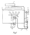
- Figure 1 shows a conventional LPG fuelled internal combustion engine 1 for a fork lift truck having a maximum speed of the order of 3000rpm and modified to incorporate an embodiment of the present invention.
- the crankshaft pulley 2 in addition to driving a water pump (not shown) and a fan 3 as is conventional, drives an air pump 4 via a drive belt 5.
- the inlet of the air pump is connected to a hose 6 to take air from the air intake filter 7 and the pump 4 pumps the air via a hose 8 into the exhaust system of the engine upstream of a catalyst in a catalytic converter 9, for converting the carbon monoxide in the exhaust gas to carbon dioxide, to provide oxygen for the conversion.
- the catalytic converter 9 is arranged in the exhaust system downstream of the exhaust manifold 10 and between the manifold and the exhaust downpipe 11.
- the converter is provided with a first inlet duct 13 for receiving exhaust gas from the manifold and provided at its inlet end with a flange 12 for connection to a similar flange on the manifold outlet.
- a flange 14 is also provided on the end of an outlet duct 15 for the converter for connection to a flange on the exhaust downpipe 11.
- the converter with ducts 13 and 15 is shown in greater detail in Figures 2 to 4. As shown the outlet end of the duct 13 is connected by an overlapping sleeve connection to the inlet of a housing in which a catalyst matrix 19 is received. The outlet of the housing is connected in the same way to the duct 15.
- the catalyst matrix may, for example be of a type manufactured by Johnson Matthey.
- a second duct 16 for introducing air into the exhaust gas upstream of the catalyst matrix is in this embodiment arranged in the first duct 13 and is provided with a threaded connection 16a for attachment to the air hose 8. Exhaust gas and air are mixed together upstream of the catalyst matrix and the mixture supplied to the matrix in which the majority of the carbon monoxide is converted into carbon dioxide.
- FIGS 2 to 4 show an embodiment of apparatus for introducing one gas into a stream of another gas which has been found to provide a very high level of carbon monoxide removal efficiency.
- the second duct 16 extends across the first duct 13 transversely with respect to the axis of the duct 13.
- duct 13 is circular in section and the duct 16 extends diametrically across it.
- the downstream end of the duct 16 is closed and may be fixed to the wall of the first duct 13 for example by welding.
- the upstream end of the duct 16 projects through the wall of the duct 13 and is provided with the threaded connection 16a as described above, for connection to the hose 8.
- the duct 16 is provided with opening means 18 for flow therethrough of air from the duct 16 into duct 13 to mix with the exhaust gas.
- the opening means extend longitudinally of the duct 16 and are arranged to open into duct 13 generally transversely of the direction of flow of exhaust gas in duct 13 and are preferably arranged symmetrically of the axis of the duct 16.
- the opening means 18 comprise a plurality of openings 18a, 18b etc spaced apart along the length of the duct 16 in two linear arrays positioned symmetrically about the axis of the duct 16 along each side of the duct 16 with the individual openings facing generally perpendicularly to the direction of flow of exhaust gas through duct 13 and to the direction of the axis of duct 13.
- each array comprises three circular openings 18a, 18b, 18c.
- the diameters of the openings 18a, 18b, 18c are in the ratio 5:6:8 and the spacing between the centres of the openings 18a and 18b is approximately 4/5ths of the spacing between the centres of the openings 18b and 18c.
- the opening means may take other forms which have flow sections which decrease in the direction of the closed end of duct 16.
- the opening means may comprise a pair of, or two linear arrays of, slots of varying width extending longitudinally of the duct 16, one slot or one array arranged on each side of the duct 16 to open into duct 13 perpendicularly of the axis of duct 13.
- the duct 16 may be provided with a plurality of similarly sized holes distributed along the length on each side of the duct 16, the density of the holes decreasing in the direction of the closed end.
- the air supplied to the second duct 16 is at a pressure which is substantially higher than the pressure of the exhaust gas in the duct 13.
- the pressure of the air may be about double the pressure of the exhaust gas.
- the pressure of the air may be of the order of 150mm Hg.
- the rate of flow of the air into duct 13 is arranged to provide sufficient oxygen to the catalyst for the anticipated maximum carbon monoxide level at any particular engine speed and load. For example, for a four cylinder engine having a capacity of 1971 cc, at an engine speed of 2000 rpm and a maximum load of 26.9 kilowatts, air is pumped by the pump 4 at a rate of 20 cubic feet a minute, the exhaust gas flow rate being about 299 cubic feet per minute.
- an advantage of driving the pump 4 directly from the engine is that its speed will vary with the engine speed. Consequently the pump can be arranged to 'match' the supply of air to the supply of exhaust gas so as to ensure that sufficient oxygen is supplied to the catalyst to remove substantially all carbon monoxide even when the engine is running in a condition producing maximum carbon monoxide, yet not to supply so much air that it reduces the temperature of the mixture at the catalyst to a temperature below the threshold temperature at which the catalyst operates.
- the pump 4 may be driven by a drive separate from the engine which may be controlled to vary the pump output with the engine speed in other ways.
- the rapid mixing of the air with the exhaust gas which is achieved by the arrangement described above means that the duct 16 can be positioned very close to the catalyst matrix, which is particularly advantageous because the space available for the catalytic converter is often very limited. As an example, very satisfactory conversion efficiency has been achieved with the duct 16 positioned only about 30 mm from the catalyst matrix. This means that, at the normal rates of exhaust gas flow in LPG fuelled internal combustion engines for fork lift trucks, the time permitted for mixing of the air with the exhaust gas before the mixture enters the catalyst matrix may be only of the order of 0.4 milliseconds.
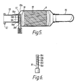
- the duct 16 may be positioned closer to the catalyst matrix, for example as shown in the embodiment of Figures 5 and 6.
- the duct 16 is located in a duct formed by the inlet portion 13a of the housing for the catalyst matrix immediately upstream of the catalyst matrix. Because the diameter of the duct 13a is larger than that of duct 13 in the previous embodiment, the duct 16 is longer than in the previous embodiment.
- the duct 16 is, as in the previous embodiment, provided with opening means 18 in the form of two linear arrays of diametrically opposed openings 18a, 18b etc having flow areas which decrease in the direction of the closed end 17 of the duct 16.
- opening means may be provided as described with reference to the previous embodiment. As shown, five openings 18a to 18e are provided in each array, the diameters of the openings being in the ratio 1:2:3:4:5 and the centres of the openings being approximately equally spaced apart in the longitudinal direction of the duct 16.
- the end 17 of the duct is, in this embodiment, closed with a plug welded to the wall of the duct 16.
- apparatus as described above can reduce a normal level of carbon monoxide in the exhaust gas of 1% to less than 0.05% and a high level of 4.5% to less than 0.15%.
- oxygen containing gas supplied to the duct 16 is air
- another oxygen containing gas which may be pure oxygen, could alternatively be supplied.
- air may be taken from another place than the air intake of the engine.
Landscapes
- Chemical & Material Sciences (AREA)
- Chemical Kinetics & Catalysis (AREA)
- Engineering & Computer Science (AREA)
- Health & Medical Sciences (AREA)
- Toxicology (AREA)
- Combustion & Propulsion (AREA)
- Mechanical Engineering (AREA)
- General Engineering & Computer Science (AREA)
- Exhaust Gas After Treatment (AREA)
- Exhaust Gas Treatment By Means Of Catalyst (AREA)
Abstract
Apparatus is provided for mixing an oxygen containing gas, for example air, with exhaust gas from a liquefied petroleum gas (LPG) fuelled internal combustion engine, the mixture being supplied to a catalytic converter to reduce the level of carbon monoxide in the exhaust gas. The apparatus comprises a first duct 13 for supplying the exhaust gas to a catalytic converter 9, and a second duct 16 having a closed end 17 extending transversely into the first duct for supplying air to mix with the exhaust gas. Opening means 18 are provided in the wall of the second duct 16 to allow air, pumped under pressure to the second duct 16 by an engine driven pump 4, to flow into the mix with the exhaust gas. The opening means 18 decrease in flow section in the direction of the closed end 17 of the second duct and open transversely of the flow of exhaust gas through the first duct to provide a high velocity flow of air causing turbulence and good mixing of the air and exhaust gases, thus enabling the catalytic converter 9 to achieve a high level of efficiency of carbon monoxide conversion.
Description
- The present invention relates to a method and apparatus for mixing fluids and particularly, but not exclusively, to a method and apparatus for mixing air with the exhaust gas of a liquefied petroleum gas (LPG) fuelled internal combustion engine to reduce the levels of carbon monoxide contained therein.
- Forklift trucks with LPG fuelled internal combustion engines are used in enclosed spaces. If the enclosed space is well ventilated and the engine is maintained at the correct running conditions, the level of carbon monoxide in the exhaust can be kept sufficiently low for safety, for example such that the requirements of the UK Health & Safety at Work Act, that atmospheric levels of carbon monoxide be less than 50 ppm, can be easily met. However, if in operation, the engine running conditions are not correctly maintained, the carbon monoxide levels in the exhaust can increase substantially. This arises because such engines have basic carburation equipment, and are much slower running than road vehicle engines, for example having a maximum speed of the order of only 3000 rpm. With road vehicles, the carburation equipment is sufficiently sophisticated that carbon monoxide levels in the exhaust vary relatively little. However, with forklift trucks the carbon monoxide in the exhaust can vary from as little as 1% under full load when the engine is correctly tuned to as much as 6.0% under full load if not correctly tuned.
- It has been proposed to remove carbon monoxide from vehicle engine exhaust gases by converting the carbon monoxide into carbon dioxide using a catalytic converter. Such equipment is in use with petrol fuelled internal combustion engines on road vehicles, but as mentioned above, its application to such vehicle engines is relatively straightforward because of the relatively small range of carbon monoxide levels encountered in such applications.
- In applying the same type of arrangement to LPG fuelled internal combustion engines for forklift trucks, the applicant has found that the efficiency of carbon monoxide removal is affected to a surprising extent by the manner in which the oxygen, which is required to support conversion, is introduced into the stream of exhaust gases flowing to the catalyst in the catalytic converter.
- According to a first aspect of the present invention there is provided apparatus for introducing a first gas into a stream of a second gas comprising a first duct for supply with the second gas and a second duct extending into a portion of the first duct transversely with respect to the axis of the first duct portion, the second duct having an open end for connection to a supply of the first gas at a pressure above that of the second gas, a closed end and opening means opening into the first duct for flow of the first gas into the first duct to mix with the second gas, the opening means extending longitudinally of the second of the second duct, the flow section of the opening means decreasing in the direction of the closed end thereof.
- The opening means may comprise a plurality of openings, which may be spaced apart along the longitudinal extent of the second duct in one or more linear arrays, the area of the openings decreasing in the direction of the closed end of the second duct. The opening means may also open generally transversely of the direction of the axis of the first duct portion. The opening means may be symmetrically disposed around the longitudinal axis of the second duct.
- The first duct portion may be circular in axial cross-section and the second duct may extend diametrically across the first duct portion.
- The first gas is preferably air, which may be pumped to the second duct.
- 0According to a further aspect of the present invention there is provided apparatus for reducing the level of carbon monoxide in the exhaust gas of an LPG fuelled internal combustion engine comprising a catalyst for converting carbon monoxide to carbon dioxide, means for supplying the exhaust gas to the catalyst comprising a first duct and means for introducing an oxygen containing gas into the stream of the exhaust gas in the first duct comprising a second duct extending into a portion of the first duct transversely with respect to the axis of the first duct portion, the second duct having an open end for connection to a pump for the supply of an oxygen containing gas under pressure, a closed end, and opening means opening into the first duct for flow of the oxygen containing gas into the first duct to mix with the exhaust gas, the opening means extending longitudinally of the second duct, the flow section of the opening means decreasing in the direction of the closed end of the second duct.
- The opening means may be as described above.
- The catalyst may be in the form of a matrix contained in a housing and the first duct portion may form part of the housing.
- The apparatus may include pump means arranged to be driven by the engine or otherwise in accordance with the speed of the engine so that its speed will vary with the engine speed.
- Preferably the oxygen containing gas is air which may be supplied from the air intake of the engine.
- According to another aspect of the present invention there is provided a method of reducing the level of carbon monoxide in the exhaust gas of an LPG fuelled internal combustion engine comprising supplying the exhaust gas along a first duct to a catalyst for converting the carbon monoxide to carbon dioxide, supplying oxygen containing gas at a pressure higher than the pressure of the exhaust gas in the first duct to a second duct having a closed end and which extends transversely of and into the first duct, the second duct having opening means through which the oxygen containing gas flows into the first duct to mix with the exhaust gas therein, the opening means decreasing in flow section towards the closed end of the second duct.
- The engine may be a relatively slow running engine having a maximum speed of the order of 3000 rpm, eg for a fork lift truck.
- Preferably the oxygen containing gas is air and the pressure of this gas is varied with the engine speed.
- Embodiments according to the present invention will now be described, by way of example only, with reference to the accompanying drawings.
- In the drawings:
- Figure 1 is a schematic side elevational view of an LPG fuelled internal combustion engine for a fork lift truck and including a first embodiment of apparatus according to the present invention;
- Figure 2 is a side elevational view of part of the engine of Figure 1 showing the first embodiment in greater detail;
- Figure 3 is an end elevation of the apparatus of Figure 2 in the direction of the arrow III in Figure 2;
- Figure 4 is a section through the apparatus of Figure 2 on the line IV-IV of Figure 3;
- Figure 5 is a section similar to that of Figure 4 through a second embodiment of apparatus according to the present invention; and
- Figure 6 is an elevational view of part of the apparatus shown in Figure 5.
- Figure 1 shows a conventional LPG fuelled internal combustion engine 1 for a fork lift truck having a maximum speed of the order of 3000rpm and modified to incorporate an embodiment of the present invention. The
crankshaft pulley 2, in addition to driving a water pump (not shown) and afan 3 as is conventional, drives an air pump 4 via adrive belt 5. The inlet of the air pump is connected to a hose 6 to take air from theair intake filter 7 and the pump 4 pumps the air via a hose 8 into the exhaust system of the engine upstream of a catalyst in acatalytic converter 9, for converting the carbon monoxide in the exhaust gas to carbon dioxide, to provide oxygen for the conversion. As shown thecatalytic converter 9 is arranged in the exhaust system downstream of theexhaust manifold 10 and between the manifold and theexhaust downpipe 11. The converter is provided with afirst inlet duct 13 for receiving exhaust gas from the manifold and provided at its inlet end with aflange 12 for connection to a similar flange on the manifold outlet. Aflange 14 is also provided on the end of anoutlet duct 15 for the converter for connection to a flange on theexhaust downpipe 11. - The converter with
ducts duct 13 is connected by an overlapping sleeve connection to the inlet of a housing in which acatalyst matrix 19 is received. The outlet of the housing is connected in the same way to theduct 15. The catalyst matrix may, for example be of a type manufactured by Johnson Matthey. - A
second duct 16 for introducing air into the exhaust gas upstream of the catalyst matrix is in this embodiment arranged in thefirst duct 13 and is provided with a threadedconnection 16a for attachment to the air hose 8. Exhaust gas and air are mixed together upstream of the catalyst matrix and the mixture supplied to the matrix in which the majority of the carbon monoxide is converted into carbon dioxide. - It has been found that the efficiency of the catalyst in removing carbon monoxide varies to a surprising extent with the manner of introduction of the air into the exhaust gas. Figures 2 to 4 show an embodiment of apparatus for introducing one gas into a stream of another gas which has been found to provide a very high level of carbon monoxide removal efficiency. The
second duct 16 extends across thefirst duct 13 transversely with respect to the axis of theduct 13. Preferably as shown,duct 13 is circular in section and theduct 16 extends diametrically across it. The downstream end of theduct 16 is closed and may be fixed to the wall of thefirst duct 13 for example by welding. The upstream end of theduct 16 projects through the wall of theduct 13 and is provided with the threadedconnection 16a as described above, for connection to the hose 8. - The
duct 16 is provided with opening means 18 for flow therethrough of air from theduct 16 intoduct 13 to mix with the exhaust gas. The opening means extend longitudinally of theduct 16 and are arranged to open intoduct 13 generally transversely of the direction of flow of exhaust gas induct 13 and are preferably arranged symmetrically of the axis of theduct 16. - Surprisingly it was found that carbon monoxide removal efficiency is optimised when the flow section of the opening means decreases in the direction of the closed
end 17 of theduct 16. - As shown the opening means 18 comprise a plurality of
openings duct 16 in two linear arrays positioned symmetrically about the axis of theduct 16 along each side of theduct 16 with the individual openings facing generally perpendicularly to the direction of flow of exhaust gas throughduct 13 and to the direction of the axis ofduct 13. In this particular embodiment each array comprises threecircular openings openings openings openings - It will be appreciated that the opening means may take other forms which have flow sections which decrease in the direction of the closed end of
duct 16. For example, the opening means may comprise a pair of, or two linear arrays of, slots of varying width extending longitudinally of theduct 16, one slot or one array arranged on each side of theduct 16 to open intoduct 13 perpendicularly of the axis ofduct 13. Alternatively theduct 16 may be provided with a plurality of similarly sized holes distributed along the length on each side of theduct 16, the density of the holes decreasing in the direction of the closed end. - The air supplied to the
second duct 16 is at a pressure which is substantially higher than the pressure of the exhaust gas in theduct 13. For example the pressure of the air may be about double the pressure of the exhaust gas. Where the back pressure of the exhaust gas is of the order of 75 mm Hg the pressure of the air may be of the order of 150mm Hg. This provides a high velocity of air flow from the opening means of theduct 16 which creates turbulence and this, combined with the distribution of the air in theduct 13 provided by the arrangement of the opening means, enables a rapid and efficient mixing of the air with the exhaust gas which in turn enables the catalyst to achieve high levels of efficiency. - The rate of flow of the air into
duct 13 is arranged to provide sufficient oxygen to the catalyst for the anticipated maximum carbon monoxide level at any particular engine speed and load. For example, for a four cylinder engine having a capacity of 1971 cc, at an engine speed of 2000 rpm and a maximum load of 26.9 kilowatts, air is pumped by the pump 4 at a rate of 20 cubic feet a minute, the exhaust gas flow rate being about 299 cubic feet per minute. - It will be appreciated that an advantage of driving the pump 4 directly from the engine is that its speed will vary with the engine speed. Consequently the pump can be arranged to 'match' the supply of air to the supply of exhaust gas so as to ensure that sufficient oxygen is supplied to the catalyst to remove substantially all carbon monoxide even when the engine is running in a condition producing maximum carbon monoxide, yet not to supply so much air that it reduces the temperature of the mixture at the catalyst to a temperature below the threshold temperature at which the catalyst operates.
- However, the pump 4 may be driven by a drive separate from the engine which may be controlled to vary the pump output with the engine speed in other ways.
- It is found that the rapid mixing of the air with the exhaust gas which is achieved by the arrangement described above means that the
duct 16 can be positioned very close to the catalyst matrix, which is particularly advantageous because the space available for the catalytic converter is often very limited. As an example, very satisfactory conversion efficiency has been achieved with theduct 16 positioned only about 30 mm from the catalyst matrix. This means that, at the normal rates of exhaust gas flow in LPG fuelled internal combustion engines for fork lift trucks, the time permitted for mixing of the air with the exhaust gas before the mixture enters the catalyst matrix may be only of the order of 0.4 milliseconds. - The above feature may be utilised to enable the
duct 16 to be positioned closer to the catalyst matrix, for example as shown in the embodiment of Figures 5 and 6. In this embodiment, which is similar to the embodiment of Figure 2 to 4 and in which the same reference numerals are used for like part, theduct 16 is located in a duct formed by theinlet portion 13a of the housing for the catalyst matrix immediately upstream of the catalyst matrix. Because the diameter of theduct 13a is larger than that ofduct 13 in the previous embodiment, theduct 16 is longer than in the previous embodiment. Theduct 16 is, as in the previous embodiment, provided with opening means 18 in the form of two linear arrays of diametricallyopposed openings closed end 17 of theduct 16. However alternative opening means may be provided as described with reference to the previous embodiment. As shown, fiveopenings 18a to 18e are provided in each array, the diameters of the openings being in the ratio 1:2:3:4:5 and the centres of the openings being approximately equally spaced apart in the longitudinal direction of theduct 16. Theend 17 of the duct is, in this embodiment, closed with a plug welded to the wall of theduct 16. - It has been found that apparatus as described above can reduce a normal level of carbon monoxide in the exhaust gas of 1% to less than 0.05% and a high level of 4.5% to less than 0.15%.
- Although as described above the oxygen containing gas supplied to the
duct 16 is air, it will be appreciated that under other circumstances another oxygen containing gas, which may be pure oxygen, could alternatively be supplied. Furthermore, where air is supplied it may be taken from another place than the air intake of the engine.
Claims (26)
1. Apparatus for introducing a first gas into a stream of a second gas comprising a first duct (13) for supply with the second gas and a second duct (16) extending into a portion of the first duct (13) transversely with respect to the axis of the first duct portion, the second duct (16) having an open end for connection to a supply of the first gas at a pressure above that of the first gas, a closed end (17) and opening means (18) opening into the first duct (13) for flow of the first gas into the first duct (13) to mix with the second gas, the opening means (18) extending longitudinally of the second duct (16), the flow section of the opening means (18) decreasing in the direction of the closed end (17) thereof.
2. Apparatus as claimed in claim 1, wherein the opening means (18) comprise an array of openings.
3. Apparatus as claimed in claim 2, wherein the openings (18) are spaced apart along the longitudinal extent of the second duct (16), the area of the openings (18) decreasing in the direction of the closed end thereof.
4. Apparatus as claimed in any of the preceding claims, wherein the opening means (18) open generally perpendicularly of the direction of the axis of the first duct portion (13).
5. Apparatus as claimed in any of the preceding claims, wherein the opening means (18) comprise at least one linear array of openings (18) spaced apart along the length of the second duct (16).
6. Apparatus as claimed in any of the preceding claims, wherein the opening means (18) are symmetrically disposed about the longitudinal axis of the second duct.
7. Apparatus as claimed in any of the preceding claims, wherein the first duct portion (13) is circular in axial cross-section and the second duct (16) extends diametrically across the first duct portion (13).
8. Apparatus for reducing the level of carbon monoxide in the exhaust gas of an LPG fuelled internal combustion engine (1) comprising a catalyst (19) for converting carbon monoxide to carbon dioxide, means (10,13) for supplying the exhaust gas to the catalyst comprising a first duct (13) and means (4,8,16) for introducing an oxygen containing gas into the stream of the exhaust gas in the first duct (13) comprising a second duct (16) extending into a portion of the first duct (13) transversely with respect to the axis of the first duct portion, the second duct having an open end for connection to a pump (4) for the supply of an oxygen containing gas under pressure, a closed end (17), and opening means (18) opening into the first duct (13) for flow of the oxygen containing gas into the first duct to mix with the exhaust gas, the opening means (18) extending longitudinally of the second duct (16), the flow section of the opening means decreasing in the direction of the closed end (17) of the second duct.
9. Apparatus as claimed in claim 8, wherein the opening means (18) comprises a plurality of openings.
10. Apparatus as claimed in claim 9, wherein the openings (18) are spaced apart along the longitudinal extent of the second duct (16) in one or more linear arrays, the areas of the openings (18) decreasing in the direction of the closed end (17) of the second duct.
11. Apparatus as claimed in any of claims 8 to 10, wherein the opening means (18) face generally perpendicularly to the direction of the axis of said first duct portion (13).
12. Apparatus as claimed in any of claims 8 to 11, wherein the second duct (16) is generally elongate and the opening means (18) are symmetrically disposed about the elongate axis thereof.
13. Apparatus as claimed in any of claims 8 to 12 wherein the first duct portion (13) is circular in axial cross-section and the second duct (16) extends diametrically across the first duct portion (13).
14. Apparatus as claimed in any of claims 8 to 13, wherein the catalyst (19) is contained within a housing and the first duct portion (13) provides part of said housing.
15. Apparatus as claimed in any of claims 8 to 14, comprising pump means (4) for supplying the oxygen containing gas to the open end of the second duct (16) at a pressure higher than the pressure of exhaust gas in the first duct (13).
16. Apparatus as claimed in claim 15, wherein the pump (4) is arranged to be driven by the engine (1) such that its speed will vary with the speed of the engine.
17. Apparatus as claimed in any of claims 8 to 16, wherein the oxygen containing gas is air supplied from the air inlet of the engine.
18. A liquefied petroleum gas fuelled internal combustion engine comprising apparatus for reducing the level of carbon monoxide in the exhaust gas therefrom as claimed in any of claims 8 to 17 connected in the exhaust gas system thereof.
19. A liquefied petroleum gas fuelled internal combustion engine comprising an exhaust gas manifold (10), a catalyst (19) for converting carbon monoxide to carbon dioxide and apparatus as claimed in any of claims 1 to 7, the first duct (13; 13a) being connected to the outlet of the exhaust gas manifold and arranged to supply the exhaust gas to the catalyst, the second duct (16) being connected to a pump (4) for supplying air thereto.
20. An engine as claimed in either claim 18 or claim 19 for a fork lift truck.
21. An engine as claimed in any of claims 18 to 20 having a maximum speed of 3000rpm.
22. An engine as claimed in any of claims 18 to 21, comprising an air pump (4) having an inlet connected to the air intake of the engine and an outlet connected to the second duct, the pump being driven from the crank shaft of the engine.
23 A method of reducing the level of carbon monoxide in the exhaust gas of an LPG fuelled internal combustion engine (1) comprising supplying the exhaust gas along a first duct (13) to a catalyst (19) for converting the carbon monoxide into carbon dioxide, supplying oxygen containing gas at a higher pressure than the pressure of the exhaust gas in the first duct to a second duct (16) having a closed end which extends transversely of and into the first duct (13), the second duct having opening means (18) through which the oxygen containing gas flows into the first duct to mix with the exhaust gas therein, the opening means (18) decreasing in flow section towards the closed end of the second duct (16), and supplying the mixture to the catalyst (19).
24. A method as claimed in claim 23, wherein the oxygen containing gas is air.
25. A method as claimed in claim 23 or 24, wherein the pressure of the oxygen containing gas is varied with engine speed.
26. A method as claimed in any of claims 23 to 25, wherein the oxygen containing gas is pumped to the second duct, the pump (4) being driven by the engine (1).
Applications Claiming Priority (2)
| Application Number | Priority Date | Filing Date | Title |
|---|---|---|---|
| GB888825149A GB8825149D0 (en) | 1988-10-27 | 1988-10-27 | Improvements in & relating to i c engines |
| GB8825149 | 1988-10-27 |
Publications (2)
| Publication Number | Publication Date |
|---|---|
| EP0366242A2 true EP0366242A2 (en) | 1990-05-02 |
| EP0366242A3 EP0366242A3 (en) | 1991-07-17 |
Family
ID=10645876
Family Applications (1)
| Application Number | Title | Priority Date | Filing Date |
|---|---|---|---|
| EP19890309031 Withdrawn EP0366242A3 (en) | 1988-10-27 | 1989-09-06 | Improvements in and relating to fluid mixing apparatus |
Country Status (10)
| Country | Link |
|---|---|
| US (1) | US4993224A (en) |
| EP (1) | EP0366242A3 (en) |
| JP (1) | JPH02123220A (en) |
| AU (1) | AU4125589A (en) |
| DK (1) | DK447389A (en) |
| FI (1) | FI894280A (en) |
| GB (1) | GB8825149D0 (en) |
| NO (1) | NO893631L (en) |
| NZ (1) | NZ230616A (en) |
| PT (1) | PT91687A (en) |
Cited By (1)
| Publication number | Priority date | Publication date | Assignee | Title |
|---|---|---|---|---|
| CN104569315A (en) * | 2015-01-21 | 2015-04-29 | 杨康莉 | Combustible gas distribution device |
Families Citing this family (3)
| Publication number | Priority date | Publication date | Assignee | Title |
|---|---|---|---|---|
| DE4115805A1 (en) * | 1991-05-15 | 1992-11-19 | Bosch Gmbh Robert | RADIAL BLOWER WITH A BLOWING WHEEL IN A SPIRAL CASE |
| US5992464A (en) * | 1998-01-09 | 1999-11-30 | Cowell; Ross A. | Pre-compression nitrox in-line blender |
| USD756872S1 (en) * | 2014-11-20 | 2016-05-24 | Stauffer Diesel, Inc. | Exhaust pipe |
Citations (5)
| Publication number | Priority date | Publication date | Assignee | Title |
|---|---|---|---|---|
| US3862540A (en) * | 1972-01-28 | 1975-01-28 | Bendix Corp | Exhaust manifold air injection system |
| JPS5279104A (en) * | 1975-12-26 | 1977-07-04 | Toyota Motor Corp | Liquefied petroleum gas internal combustion engine |
| GB2048105A (en) * | 1979-04-16 | 1980-12-10 | Gen Motors Corp | Catalytic converters for internal combustion engine exhaust gases |
| US4278639A (en) * | 1979-03-19 | 1981-07-14 | Toyo Kogyo Co., Ltd. | Catalytic converter for purifying gases |
| US4394351A (en) * | 1981-09-08 | 1983-07-19 | General Motors Corporation | Dual-monolith catalytic converter with secondary air injection |
Family Cites Families (6)
| Publication number | Priority date | Publication date | Assignee | Title |
|---|---|---|---|---|
| US2531127A (en) * | 1947-06-06 | 1950-11-21 | Hershey Creamery Company | Extrusion nozzle for intrafold ice cream |
| US3113418A (en) * | 1960-01-05 | 1963-12-10 | James B Campbell | Exhaust gas purifying method and apparatus |
| US3486326A (en) * | 1968-02-27 | 1969-12-30 | Curtiss Wright Corp | Exhaust gas reactor |
| US3613359A (en) * | 1970-01-15 | 1971-10-19 | Lear Siegler Inc | Aspirated exhaust system |
| US3734111A (en) * | 1971-12-20 | 1973-05-22 | Phillips Petroleum Co | Apparatus for in-line mixing of fluids |
| US4519423A (en) * | 1983-07-08 | 1985-05-28 | University Of Southern California | Mixing apparatus using a noncircular jet of small aspect ratio |
-
1988
- 1988-10-27 GB GB888825149A patent/GB8825149D0/en active Pending
-
1989
- 1989-09-06 EP EP19890309031 patent/EP0366242A3/en not_active Withdrawn
- 1989-09-08 US US07/404,580 patent/US4993224A/en not_active Expired - Fee Related
- 1989-09-11 FI FI894280A patent/FI894280A/en not_active Application Discontinuation
- 1989-09-11 AU AU41255/89A patent/AU4125589A/en not_active Abandoned
- 1989-09-11 PT PT91687A patent/PT91687A/en not_active Application Discontinuation
- 1989-09-11 DK DK447389A patent/DK447389A/en not_active Application Discontinuation
- 1989-09-11 JP JP1233075A patent/JPH02123220A/en active Pending
- 1989-09-11 NO NO89893631A patent/NO893631L/en unknown
- 1989-09-12 NZ NZ230616A patent/NZ230616A/en unknown
Patent Citations (5)
| Publication number | Priority date | Publication date | Assignee | Title |
|---|---|---|---|---|
| US3862540A (en) * | 1972-01-28 | 1975-01-28 | Bendix Corp | Exhaust manifold air injection system |
| JPS5279104A (en) * | 1975-12-26 | 1977-07-04 | Toyota Motor Corp | Liquefied petroleum gas internal combustion engine |
| US4278639A (en) * | 1979-03-19 | 1981-07-14 | Toyo Kogyo Co., Ltd. | Catalytic converter for purifying gases |
| GB2048105A (en) * | 1979-04-16 | 1980-12-10 | Gen Motors Corp | Catalytic converters for internal combustion engine exhaust gases |
| US4394351A (en) * | 1981-09-08 | 1983-07-19 | General Motors Corporation | Dual-monolith catalytic converter with secondary air injection |
Non-Patent Citations (1)
| Title |
|---|
| PATENT ABSTRACTS OF JAPAN vol. 1, no. 137 (M-46)() 11 November 1977, & JP-A-52 079104 (TOYOTA) 07 April 1977, * |
Cited By (1)
| Publication number | Priority date | Publication date | Assignee | Title |
|---|---|---|---|---|
| CN104569315A (en) * | 2015-01-21 | 2015-04-29 | 杨康莉 | Combustible gas distribution device |
Also Published As
| Publication number | Publication date |
|---|---|
| AU4125589A (en) | 1990-05-03 |
| NO893631L (en) | 1990-04-30 |
| DK447389D0 (en) | 1989-09-11 |
| FI894280A0 (en) | 1989-09-11 |
| NZ230616A (en) | 1991-03-26 |
| NO893631D0 (en) | 1989-09-11 |
| DK447389A (en) | 1990-04-28 |
| EP0366242A3 (en) | 1991-07-17 |
| US4993224A (en) | 1991-02-19 |
| GB8825149D0 (en) | 1988-11-30 |
| FI894280A (en) | 1990-04-28 |
| PT91687A (en) | 1990-03-30 |
| JPH02123220A (en) | 1990-05-10 |
Similar Documents
| Publication | Publication Date | Title |
|---|---|---|
| KR100628666B1 (en) | Secondary treatment device for the exhaust gases of an internal combustion engine | |
| US5456240A (en) | Engine system | |
| JP2006329019A (en) | Exhaust pipe of diesel engine | |
| US6939517B2 (en) | Nitrogen oxide reducing system for diesel engine and nitrogen gas generating device | |
| US20120042639A1 (en) | Multi-engine system with on-board ammonia production | |
| CA2438535A1 (en) | Air turbine for combustion engine | |
| US4517926A (en) | Device for improving fuel efficiency and method of use therefor | |
| CN1177997C (en) | Two-stroke internal combustion engine | |
| US4993224A (en) | Fluid mixing apparatus | |
| US5455012A (en) | Exhaust gas purifying apparatus | |
| US20050126513A1 (en) | On-board diesel oil and water emulsification system | |
| WO1993024745A1 (en) | Catalytic combustion engine exhaust gas purifier with additional air supply | |
| US4916898A (en) | Method for treatment of exhaust gases | |
| US5287828A (en) | Engine intake flow booster | |
| KR100404585B1 (en) | sub muffler of an automobile exhaust equipment | |
| KR100493415B1 (en) | AN INTERNAL COMBUSTION ENGINE HAVING A REACTOR FOR REDUCTION OF THE NOχ CONTENT IN THE EXHAUST GAS, AND A METHOD | |
| US4454841A (en) | Automatic liquid thermal pressure regulator and balancing system | |
| JP3504914B2 (en) | Nitrogen oxide reduction equipment and nitrogen gas generator for diesel engines | |
| US20080295494A1 (en) | Multi-engine system with on-board ammonia production | |
| US6732508B2 (en) | Exhaust system for an internal combustion engine and engine comprising the same | |
| RU198338U1 (en) | The device for exhaust gas exhaust of internal combustion engines into the atmosphere | |
| CN201031748Y (en) | Device for reducing discharged pollution produced by car engine and high-efficiency fuel-economizing | |
| CN2344566Y (en) | Engine membrane separation oxygen-enrichment fuel-saving device | |
| WO1998030797A1 (en) | Fuel/air mixing device for internal combustion engine | |
| KR20010069384A (en) | Extend Adjustor Swirl (Whirl) Device |
Legal Events
| Date | Code | Title | Description |
|---|---|---|---|
| PUAI | Public reference made under article 153(3) epc to a published international application that has entered the european phase |
Free format text: ORIGINAL CODE: 0009012 |
|
| AK | Designated contracting states |
Kind code of ref document: A2 Designated state(s): AT BE CH DE ES FR GB GR IT LI LU NL SE |
|
| PUAL | Search report despatched |
Free format text: ORIGINAL CODE: 0009013 |
|
| AK | Designated contracting states |
Kind code of ref document: A3 Designated state(s): AT BE CH DE ES FR GB GR IT LI LU NL SE |
|
| STAA | Information on the status of an ep patent application or granted ep patent |
Free format text: STATUS: THE APPLICATION IS DEEMED TO BE WITHDRAWN |
|
| 18D | Application deemed to be withdrawn |
Effective date: 19910717 |