EP0366222B1 - Wiederladegerät für Patronen - Google Patents
Wiederladegerät für Patronen Download PDFInfo
- Publication number
- EP0366222B1 EP0366222B1 EP89304654A EP89304654A EP0366222B1 EP 0366222 B1 EP0366222 B1 EP 0366222B1 EP 89304654 A EP89304654 A EP 89304654A EP 89304654 A EP89304654 A EP 89304654A EP 0366222 B1 EP0366222 B1 EP 0366222B1
- Authority
- EP
- European Patent Office
- Prior art keywords
- turret
- plunger
- bushing
- die holder
- reloader
- Prior art date
- Legal status (The legal status is an assumption and is not a legal conclusion. Google has not performed a legal analysis and makes no representation as to the accuracy of the status listed.)
- Expired - Lifetime
Links
- 230000007246 mechanism Effects 0.000 claims description 14
- 238000006243 chemical reaction Methods 0.000 claims description 3
- 238000009420 retrofitting Methods 0.000 abstract 2
- 238000003825 pressing Methods 0.000 description 4
- 230000009471 action Effects 0.000 description 2
- 230000000694 effects Effects 0.000 description 2
- 238000000034 method Methods 0.000 description 2
- 230000008569 process Effects 0.000 description 2
- 239000004698 Polyethylene Substances 0.000 description 1
- 230000008901 benefit Effects 0.000 description 1
- 239000002783 friction material Substances 0.000 description 1
- 238000004519 manufacturing process Methods 0.000 description 1
- -1 polyethylene Polymers 0.000 description 1
- 229920000573 polyethylene Polymers 0.000 description 1
- 239000000843 powder Substances 0.000 description 1
Images
Classifications
-
- F—MECHANICAL ENGINEERING; LIGHTING; HEATING; WEAPONS; BLASTING
- F42—AMMUNITION; BLASTING
- F42B—EXPLOSIVE CHARGES, e.g. FOR BLASTING, FIREWORKS, AMMUNITION
- F42B33/00—Manufacture of ammunition; Dismantling of ammunition; Apparatus therefor
- F42B33/004—Cartridge loaders of the rotatable-turret type
-
- Y—GENERAL TAGGING OF NEW TECHNOLOGICAL DEVELOPMENTS; GENERAL TAGGING OF CROSS-SECTIONAL TECHNOLOGIES SPANNING OVER SEVERAL SECTIONS OF THE IPC; TECHNICAL SUBJECTS COVERED BY FORMER USPC CROSS-REFERENCE ART COLLECTIONS [XRACs] AND DIGESTS
- Y10—TECHNICAL SUBJECTS COVERED BY FORMER USPC
- Y10T—TECHNICAL SUBJECTS COVERED BY FORMER US CLASSIFICATION
- Y10T29/00—Metal working
- Y10T29/51—Plural diverse manufacturing apparatus including means for metal shaping or assembling
- Y10T29/5152—Plural diverse manufacturing apparatus including means for metal shaping or assembling with turret mechanism
- Y10T29/5165—Plural diverse manufacturing apparatus including means for metal shaping or assembling with turret mechanism including rotating and/or locking means
-
- Y—GENERAL TAGGING OF NEW TECHNOLOGICAL DEVELOPMENTS; GENERAL TAGGING OF CROSS-SECTIONAL TECHNOLOGIES SPANNING OVER SEVERAL SECTIONS OF THE IPC; TECHNICAL SUBJECTS COVERED BY FORMER USPC CROSS-REFERENCE ART COLLECTIONS [XRACs] AND DIGESTS
- Y10—TECHNICAL SUBJECTS COVERED BY FORMER USPC
- Y10T—TECHNICAL SUBJECTS COVERED BY FORMER US CLASSIFICATION
- Y10T29/00—Metal working
- Y10T29/53—Means to assemble or disassemble
- Y10T29/53313—Means to interrelatedly feed plural work parts from plural sources without manual intervention
- Y10T29/53374—Means to interrelatedly feed plural work parts from plural sources without manual intervention including turret-type conveyor
-
- Y—GENERAL TAGGING OF NEW TECHNOLOGICAL DEVELOPMENTS; GENERAL TAGGING OF CROSS-SECTIONAL TECHNOLOGIES SPANNING OVER SEVERAL SECTIONS OF THE IPC; TECHNICAL SUBJECTS COVERED BY FORMER USPC CROSS-REFERENCE ART COLLECTIONS [XRACs] AND DIGESTS
- Y10—TECHNICAL SUBJECTS COVERED BY FORMER USPC
- Y10T—TECHNICAL SUBJECTS COVERED BY FORMER US CLASSIFICATION
- Y10T74/00—Machine element or mechanism
- Y10T74/14—Rotary member or shaft indexing, e.g., tool or work turret
- Y10T74/1418—Preselected indexed position
- Y10T74/1424—Sequential
Definitions
- This invention relates to cartridge reloading devices used to reload spent cartridge cases.
- a single station reloading tool or device typically includes a fixture that is secured to a workbench.
- the fixture include a guide for a plunger and a mechanism for manually moving the plunger up and down in the guide.
- the top of the plunger is designed to receive a cartridge case.
- the fixture also includes a die holding plate aligned above the plunger.
- Various dies are provided for sequential interchangeable mounting in the die holding plate. The cartridges are individually positioned on the plunger and pressed into the first die. The die is replaced and the process repeated as many times as required for completion of the reloading process.
- a single station reloading tool is known from US-A-3 259 007.
- dies may be positioned in a circular pattern, and cartridge cases are loaded in sequence on an indexable rotatable turret, the cartridge cases being operated on in sequence at the multiple stations. For example, if there are four reloading stations, the first cartridge case is placed on the turret and the plunger is activated to perform the first step. The turret is then indexed to place the cartridge in line with the next die station and a second cartridge is placed on the turret in line with the first die station. The plunger is activated to accomplish two independent reloading die functions. Third and fourth cartridges are added in sequence until four reloading steps are simultaneously performed on different cartridges.
- Multi-station reloading tools are known from US-A-3 483 792 and US-A-4 515 063.
- multi-station reloading is that all of the reloading operations accomplished by a single stage reloader by the use of a sequence of replaceable dies are accomplished in a single pressing operation.
- Each cartridge must of course go through the multiple pressing stages, so that for each cartridge, the device must be operated the same number of times.
- the advantage resides in the fact that for example four different functions are being performed on four different cartridges with a single stroke of the reloader device.
- a multi-station reloading device is substantially more expensive than a single station device and it would accordingly be advantageous to provide a kit permitting owners of a single station device to convert it to a multi-station device.
- the invention accordingly provides an apparatus for converting, to a multiple station reloader, a single station cartridge reloader having a reciprocable cartridge holding plunger aligned with an opening of a die holder arranged for receiving a reloading die, the apparatus comprising a plunger extension arranged to be coupled to the plunger to protrude through the die holder opening, a turret mounted on the plunger extension to reciprocate therewith, a secondary die holder arranged to be fixedly mounted to the single station cartridge reloader in spaced relation to the turret, a plurality of cartridge holding stations on the turret arranged symmetrically around an upright axis, a corresponding plurality of die receiving stations on the secondary die holder similarly arranged around the upright axis, whereby cartridges placed in the cartridge receiving stations are aligned with dies positioned in the die receiving stations, the turret being rotatable about the axis for indexing the cartridges relative to the dies positioned in the die receiving stations.
- the invention relates also to a multiple station reloader as defined in claim 4.
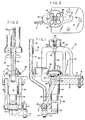
- Figs. 1 and 2 illustrate a cartridge reloading device 10 including a support structure having a flange 14 and support posts 18 and 20 integral therewith.
- Bolts 16 extend through the flange 14 to secure the reloading device to a table 12.
- the support posts 18 and 20 support an overhead die holder 22, ada plunger guide 24 depends from the flange 14.
- a plunger 26 is guided for vertical, reciprocal sliding movement through the guide 24 as indicated by arrows 28.
- An L-shaped pivotal bracket 30 has one end pivotally attached at a pivot 32 to the bottom of the plunger 26 and the other end pivotally attached at a pivot 34 to the lower ends of a pair of parallel arms 36.
- the upper ends of the arms 36 are pivotally attached at a pivot 38 to the support structure, specifically, to the plunger guide 24 and the flange 14.
- An elongate handle bar 42 mounts a handle 40 and is attached to the pivotal bracket 30.
- the handle bar 42 extends through the pivotal bracket 30 and has a nut 44 screwed onto its protruding end. Pulling the handle as indicated by arrow 46 effects rotation of the pivotal bracket 30 about pivot 34 as indicated by arrow 48, which in turn effects upward movement of the plunger 26.
- a cartridge holder of the device comprises a rotatable turret 50 having provision for holding a plurality of cartridges in a circular pattern symmetrically positioned around its axis of rotation and the axis of the plunger 26.
- a mounting mechanism 52 for mounting the turret 50 to the plunger 26 provides for rotative movement of the turret relative to the plunger 26.
- the die holder 22 is provided with a plurality of dies 54 arranged in the same circular symmetrical pattern as the cartridges in the turret 50. The two circular patterns are in line with the plunger movement so that the turret 50 can be rotated to place the cartridges in line with the dies 54.
- a cartridge case or cartridge 52 is placed in the turret 50 under the first die and the press is operated to perform the first die operation.
- the cartridge is indexed successively to the second, third and fourth die positions and the second, third and fourth die operations are accomplished.
- Mechanism 71 functions to seat a primer in the cartridge between the first and second die operations.
- the cartridge is removed and a new one inserted into the turret in its place. It will be appreciated that a completed cartridge is removed and a new cartridge is inserted after each pressing operation, so that there are four cartridges in the turret, each at a different stage of completion and going through the die operations in sequence.
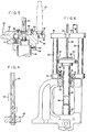
- the mounting mechanism 52 as best seen in Fig. 5 includes a base plate 58 integral with a collar 56 that is fixedly clamped to the top of the plunger 26 by a lock screw 57, so as to be non-rotatable relative to the plunger.
- the turret 50 is rotatably mounted to the base plate 58 and has configured U-shaped cut outs 51 at four cartridge receiving positions. Each U-shaped cut out 51 is designed for receiving the rim 55 of a cartridge 53 which is slid into the cut out.
- the tubular casing that projects from the rim of the cartridge is nested in the U-shaped cut out and projects upwardly from the turret 50. As the turret is rotated about its rotatable mounting to the base plate 58, the cartridges slide around the base plate through the different die stations.
- a shaft 60 Projecting upwardly from the turret 50 along the rotatable axis thereof is a shaft 60.
- the shaft 60 is fixed to the turret 50 so that the shaft and turret rotate together.
- the shaft projects up through the die holder 22 of the support structure, specifically, it projects through a bushing 63 in a centre opening in the die holder. Rotation of the bushing 63 is controlled in part by a one-way clutch mechanism 62.
- the opening in the die holder and thus the axis of the bushing 63 is located centrally of the circular pattern of the dies 54.
- the bushing 63 has an inner configuration that fits the cross section of the shaft 60 which, as illustrated, is a hexagon. The fit as between the shaft and the bushing is designed to allow vertical sliding of the shaft 60 through the bushing 63.
- the bushing is preferably of a low friction material such a polyethylene or it may be a ball type bushing of the kind used as a component of a roller clutch bushing.
- An acceptable roller clutch bushing is available from The Torrington Company of Torrington, Connecticut, a specific roller clutch used in actual production of the device being identified by catalog No. RC-0061008. In any event, rotation of the bushing 63 is permitted by the clutch in one direction and not in the other. Numerous types of mechanisms are available for performing this one-way clutch function and further description is deemed unnecessary.
- the shaft 60 is twisted on its axis over a portion 64 near the top of the shaft.
- the angular offset of the twist is 90° corresponding to one-quarter of a complete turn of 360°.
- the shaft 60 is forced up and down through the bushing 63, by operation of the handle 40 to force reciprocating moving of the plunger 26, and as the twist portion 64 passes through the bushing 63, the bushing is urged to rotate a corresponding quarter turn relative to the shaft.
- the arrangement of the twist on the shaft 60 and the bushing 63 is such that the bushing can turn within the one-way clutch mechanism 62 in the direction in which it is urged when the shaft 60 is forced upwards through the die holder portion 22, but the bushing is prevented from turning in the direction in which it is urged when the shaft is moved downwardly.
- the turret is fixed to the shaft 60 by a bracket 66 best seen in Fig. 5, and thus turning of the shaft turns the turret 50.
- Form Fig. 5 it will be seen that the underside of the turret 50 is provided with alignment detents 68. These detents are located at four positions around the turret. A spring-urged ball 70 projected from the base plate 58, is aligned for seating in the detents 68 at each of the four positions in which the cartridges in the turret 50 are aligned with the dies 54 in the die holder 22.
- FIG. 6 A reloading device in accordance with the invention is shown in Fig. 6 in which parts identical or similar to parts of the device of Figures 1-5 are indicated by the same reference numerals which are however primed.
- the basic structure of the device is designed for single station reloading.
- a centre opening 72 in the die holder section 22′ is arranged for receiving a replaceable die.
- the plunger 26′ is arranged to receive a cartridge holder aligned with the opening 72 and thus with a die mounted in the opening.
- the operation of a single station reloading apparatus has been previously explained.
- such a single station reloading device is converted as illustrated in Fig. 6 to a multiple station reloader having features similar to those of the reloading device of Figs. 1-5.
- An adapter kit including the components for converting the one-station reloader includes a support plate 74 that is secured to the die holder plate 22' by a mounting nut 76 screwed through plate 74 and into the threaded die opening 72.
- a secondary die holder 78 is suspended over support plate 74 by posts 80.
- the die holder 78 is similar to the die holder 22 of Figs 1-5 in having a centre opening that contains a bushing 63' with a one-way clutch mechanism 62', together with dies 54' arranged in a symmetrical circular pattern around the bushing.
- a plunger extension member 82 is mounted to the plunger 26' by means of an adapter 83 and extends upwardly through a centre opening in the mounting nut 76.
- a turret 50' again similar to that of Fig. 1, is carried on a base plate 58' which is mounted by a collar 56' to the plunger extension member 82.
- a shaft 60' extends up from the turret through the bushing 63'. The turret is indexed relative to the base plate by the action of the shaft 60' forced through the bushing, all in the manner previously explained with reference to Figs. 1-5.
Landscapes
- Engineering & Computer Science (AREA)
- Manufacturing & Machinery (AREA)
- General Engineering & Computer Science (AREA)
- Punching Or Piercing (AREA)
- Machine Tool Positioning Apparatuses (AREA)
- Water Treatment By Sorption (AREA)
- Valve Device For Special Equipments (AREA)
- Valve-Gear Or Valve Arrangements (AREA)
Claims (11)
- Ein Gerät zur Umrüstung, auf Mehrstellen-Wiederlader, eines einstelligen Patronen-Wiederladers mit hin- und herbewgbarem Patronenträgerkolben (26) welcher an die öffnung eines zum Empfang einer Wiederladungssenke konstruierten Senkenträgers (22) ausgerichtet ist, das Gerät bestehend aus:
einer Kolbenverlängerung (82) welche zur Ankopplung an den Kolben konstruiert ist um aus der öffnung des Senkenträgers herauszuragen, einer Drehscheibe (50) welche an der Kolbenverlängerung befestigt ist um mit dieser hin- und herfahren zu können, einem Hilfs-Senkenträger (78) so konstruiert, daß er fest auf dem einstelligen Patronen-Wiederlader im festem Positionsverhältnis mit der Drehscheibe getragen ist, einer Mehrzahl von Patronenträgerstellen auf der Drehscheibe, symmetrisch um eine senkrechte Achse herum konstruiert, einer entsprechenden Mehrzahl von Senken-Empfängerstellen auf dem Hilfs-Senkenträger ähnlicherweise um die senkrechte Achse herum konstruiert, wodurch in die Patronen-Empfängerstellen eingesetzten Patronen (53) auf die Senken (54) die sich in den Senken-Aufnahmestellen befinden, ausgerichtet sind, wobei die Drehscheibe um die Achse herum drehbar ist, mit dem Zweck der Index-Schritteinstellung der Patronen im Verhältnis zu den in den Senken-Empfängerstellen liegenden Senken. - Ein Gerät nach Anspruch 1, dadurch gekennzeichnet, daß es zu einem Hilfsträger (74) zum Tragen des Hilfs-Senkenträgers (78) im festem Positionsverhältnis ist, und ein Trägerteil (76) welches an dem Hilfsträger befestigt ist und mittels Gewinde in die öffnung des Senkenträgers (22) des einstelligen Wiederladers einbringbar ist, wobei das Trägerteil eine Führungsöffnung besitzt, durch welche die Kolbenverlängerung (82) schiebbar geführt wird.
- Ein Gerät nach Ansprüchen 1 oder 2, dadurch gekennzeichnet daß es eine Index-Schrittvorrichtung (62) hat, welche auf Hin- und Herbewegung der Kolbenverlängerung (82) reagiert, zwecks automatischer Index-Schritt-einstellung der Drehscheibe (50) entsprechend Hin- und Herbewegung des Kolbens (26).
- Ein Mehrstellen- Patronenwiederlader, bestehend aus einem einstelligen Patronen-Wiederlader und einer Umrüstungseinrichtung, dadurch gekennzeichnet, daß der einPatronen-Wiederlader aus einem Kolben (26) besteht, welcher in der Lage ist, eine Patrone zu tragen, und welcher schieber getragen ist durch einen Träger zwecks Auf- und Abbewegung im Verhältnis zu dem Träger, und einem oberen Senkenträger (22) welcher fest an dem Träger befestigt ist und welcher eine öffnung zum Empfang einer Senke besitzt, welche auf den Kolben ausgerichtet ist und wogegen das Umrüstungs-gerät aus einer Kolbenverlängerung (82) besteht, welche an den Kolben angekoppelt ist und welches aus der oberen Senkenträger-öffnung herausragt, eine Drehplatte (50) drehbar gehalten auf der Kolbenverlängerung zwecks Auf- und Abfahren entsprechend der Auf-und Abfahrt des Kolbens, ein Hilfs-Senkenträger (78) welcher fest auf dem Träger in festem senkrechten Positionsverhältnis mit der Drehscheibe befestigt ist, eine Mehrzahl von Patronen-Trägerstellen auf der Drehscheibe, welche symmetrisch um eine senkrechte Achse herum konstruiert sind, eine entsprechende Mehrzahl von Senken-Empfängerstellen auf dem Hilfs-Senkenträger, welche ebenfalls um die senkrechte Achse herum konstruiert sind, wodurch Patronen (53) welche in die Patronen-Empfängerstellen eingesteckt sind, mit den Senken (54) in den Senken-Aufnahmestellen ausgerichtet werden, und Index-Schritt-Einstellungsvorrichtungen (62) welche Index-Schrittsetzung der Drehscheibe aufeinanderfolgende Winkel-Indexlagen ermöglichen.
- Ein Wiederladungsgerät nach Anspruch 4, gekennzeichnet dadurch daß die Index-Schritt-Einstellungsvorrichtung aus einem Futterstück (63) besteht, welches drehbar in einer mittleren öffnung in dem Hilfs-Senkenträger (78) angebracht ist, eine Einweg-Kupplungsvorrichtung welche das Drehen des Futterstückes in einer Richtung gestattet, und dessen Drehung in der anderen Richtung verhindert, und eine Index-Schrittwelle (60) welche fest an der Drehscheibe (50) befestigt ist, und welche aus diesem durch das Futterstück hervorragt, wobei die Welle und das Futterstück komplementäre Querschnitts-Konstruktionen haben, welche schiebbare Bewegung der Welle durch das Futter-stück gestatten, aber relative Drehung der Welle und des Futterstückes verhindern, wobei ein Teil der Welle auf spirale Weise verdreht ist, so daß Verschiebung der Wellenlage durch das Futterstück in einer Richtung dessen Drehung verursacht, in derjenigen Richtung, welche durch die Einweg-Kupplungsvorrichtung gestattet ist, und Bewegung der Welle in der anderen Richtung bewirkt Index-Schrittbewegung der Welle und der Drehscheibe.
- Ein Wiederlader nach Anspruch 5, gekennzeichnet dadurch, daß die Einweg-Kupplungsvorrichtung (62) Drehung des Futterstückes (63) bei Hinaufbewegung des Kolbens (26) gestattet, wodurch Drehungs-Indexschritt-Einstellung der Drehscheibe (50) bei Hinunterhub des Kolbens stattfindet.
- Ein Wiederlader nach Ansprüchen 5 oder 6, gekennzeichnet dadurch daß die Konstruktion der Welle ein mehrseitiges Polygon ist und der verdrehte Abschnitt dieser Welle eine Winkelverschiebung der Polygon-Konstruktion verursacht, durch denselben Winkel wie der zwischen den Wiederladungssenken in dem Hilfs-Senkenträger (78).
- Ein Wiederlader nach Ansprüchen 5, 6 oder 7, gekennzeichnet dadurch, daß er Ausrichtungsvorrichtungen (68,70) hat, weiche drehende Wendung der Drehscheibe (50) widerstehen aber sie gestattet in solchen Winkellagen in weichen die Patronen in der Drehscheibe (50) und in den Senken in dem Hilfs-Senkenträger (78) aufeinander ausgerichtet sind, wobei die Ausrichtungsvorrichtung Drehen der Drehscheibe genügend widersteht, um Drehen des Futterstückes (63) zu erzwingen, wie diese durch die Einweg-Kopplungsvorrichtung (62) gestattet ist.
- Ein Wiederlader nach Anspruch 8, gekennzeichnet dadurch daß er eine Bodenplatte (58) zur Befestigung der Kolbenverlägerung (82) hat, und auf welcher die Drehplatte (50) drehbar getragen ist, und worin die Ausrichtungsvorrichtung aus einer Feder-vorgespannten Kugel (70) und einer Rastvertiefung (68) besteht, welche zwischen der Drehplatte und der Bodenplatte wirkt.
- Ein Wiederlader nach irgendwelchen der Ansprüche 4 - 9, gekennzeichnet dadurch daß die Trägervorrichtung aus einer Trägermutter (76) besteht, welche so konstruiert ist, daß sie in dem Senkenträger (22) empfangen wird, um die Hilfs-Trägerstruktur zu tragen, wobei die Trägermutter eine Bohrung hat, um das Kolben-Verlängerungsteil (82) durchzulassen.
- Ein Wiederlader nach irgendwelchen der Ansprüche 4 - 10 gekennzeichnet dadurch daß er einen Hilfsträger (74) hat, welcher den Hilfs-Senkenträger (78) in senkrechtem Verhältnis stützt, und ein Trägerteil (76) welches an dem Hilfsträger befestigt, und mittels Gewinde in der öffnung des oberen Senkenträgers (22) gesichert ist, wobei das Trägerteil eine Führungsöffnung besitzt, durch weiche die Kolbenverlängerung schiebbar durchgeführt ist.
Priority Applications (1)
| Application Number | Priority Date | Filing Date | Title |
|---|---|---|---|
| AT89304654T ATE101917T1 (de) | 1988-10-24 | 1989-05-09 | Wiederladegeraet fuer patronen. |
Applications Claiming Priority (2)
| Application Number | Priority Date | Filing Date | Title |
|---|---|---|---|
| US261273 | 1988-10-24 | ||
| US07/261,273 US4841831A (en) | 1988-10-24 | 1988-10-24 | Indexing reloader of cartridges |
Publications (2)
| Publication Number | Publication Date |
|---|---|
| EP0366222A1 EP0366222A1 (de) | 1990-05-02 |
| EP0366222B1 true EP0366222B1 (de) | 1994-02-23 |
Family
ID=22992588
Family Applications (1)
| Application Number | Title | Priority Date | Filing Date |
|---|---|---|---|
| EP89304654A Expired - Lifetime EP0366222B1 (de) | 1988-10-24 | 1989-05-09 | Wiederladegerät für Patronen |
Country Status (5)
| Country | Link |
|---|---|
| US (2) | US4841831A (de) |
| EP (1) | EP0366222B1 (de) |
| AT (1) | ATE101917T1 (de) |
| AU (1) | AU607865B2 (de) |
| DE (1) | DE68913266D1 (de) |
Families Citing this family (14)
| Publication number | Priority date | Publication date | Assignee | Title |
|---|---|---|---|---|
| US5040449A (en) * | 1990-11-30 | 1991-08-20 | Lee Richard J | Shotgun shell reloader |
| US5202529A (en) * | 1991-12-16 | 1993-04-13 | Blount, Inc. | Convertible ammunition reloading press |
| US5239923A (en) * | 1992-03-01 | 1993-08-31 | Harco Graphic Products, Inc. | Screen printer |
| US5693905A (en) * | 1996-09-16 | 1997-12-02 | Blount, Inc. | Primer loading tool |
| US5831197A (en) * | 1997-05-05 | 1998-11-03 | Blount, Inc. | Primer strip loading tool |
| US5900574A (en) | 1997-09-19 | 1999-05-04 | Hart; Larry L. | Reloading apparatus which automatically sets a bullet into the mouth of a casing |
| DE19840739A1 (de) * | 1998-09-08 | 2000-03-09 | Zimbo Fleisch Und Wurstwaren G | Fleischprodukt mit einem Gehalt von weniger als 0,5-Gew..-% Fett |
| US6260463B1 (en) | 1999-08-11 | 2001-07-17 | Blount, Inc. | Hand-held primer loading tool |
| US6233799B1 (en) * | 2000-01-26 | 2001-05-22 | Ronald B. Bennett | Cylinder sizer and method thereof |
| US6772668B2 (en) | 2002-08-07 | 2004-08-10 | Alliant Techsystems, Inc. | Ammunition reloading apparatus with feed mechanism |
| US6826865B2 (en) | 2003-02-10 | 2004-12-07 | Clymer Manufacturing Co. | Gun chambering device |
| WO2014150007A1 (en) | 2013-03-15 | 2014-09-25 | Alliant Techsystems Inc. | Reloading kit with lead free bullet composition |
| USD721159S1 (en) | 2013-06-14 | 2015-01-13 | Raymond Paul Reneau | Equipment support |
| US10318904B2 (en) | 2016-05-06 | 2019-06-11 | General Electric Company | Computing system to control the use of physical state attainment of assets to meet temporal performance criteria |
Family Cites Families (14)
| Publication number | Priority date | Publication date | Assignee | Title |
|---|---|---|---|---|
| US2854861A (en) * | 1941-10-31 | 1958-10-07 | Milford G Loder | Advancing and locking mechanism |
| US2967440A (en) * | 1959-05-11 | 1961-01-10 | Pettibone Mulliken Corp | Hydraulic indexing mechanism for foundry turntables |
| US3157086A (en) * | 1962-01-18 | 1964-11-17 | Theodore J Bachhuber | Shotgun shell reloader |
| US3259007A (en) * | 1964-07-21 | 1966-07-05 | Emhart Corp | Cartridge reloading tool with improved primer insertion and extractor means |
| US3483792A (en) * | 1968-01-23 | 1969-12-16 | Charles F Williams | Automatic cartridge reloader |
| US3771411A (en) * | 1972-07-03 | 1973-11-13 | Ponsness Warren | Shotgun cartridge loading machine |
| US4031804A (en) * | 1975-06-16 | 1977-06-28 | Pacific Gunsight Company | Rotary shot shell reloader |
| US4163410A (en) * | 1977-11-07 | 1979-08-07 | Dillon Michael J | Shell reloading machine |
| US4287748A (en) * | 1979-09-28 | 1981-09-08 | Stewart Stamping Corp. | Rotary transfer press apparatus |
| US4343222A (en) * | 1980-10-16 | 1982-08-10 | Dillon Michael J | Shell reloading machine |
| US4393744A (en) * | 1981-07-06 | 1983-07-19 | Lee Richard J | Press for reloading rifle and pistol cartridges |
| US4515063A (en) * | 1983-08-22 | 1985-05-07 | Lee Richard J | Turret press for reloading rifle and pistol cartridges |
| US4526084A (en) * | 1983-09-23 | 1985-07-02 | Hornady Manufacturing Co. | Shell loader |
| US4817491A (en) * | 1988-07-28 | 1989-04-04 | Arthur Fenton | Apparatus for a firearm ammunition hand loader |
-
1988
- 1988-10-24 US US07/261,273 patent/US4841831A/en not_active Ceased
-
1989
- 1989-05-09 DE DE89304654T patent/DE68913266D1/de not_active Expired - Lifetime
- 1989-05-09 AT AT89304654T patent/ATE101917T1/de not_active IP Right Cessation
- 1989-05-09 EP EP89304654A patent/EP0366222B1/de not_active Expired - Lifetime
- 1989-08-04 AU AU39317/89A patent/AU607865B2/en not_active Ceased
-
1990
- 1990-06-05 US US07/533,527 patent/USRE34612E/en not_active Expired - Lifetime
Also Published As
| Publication number | Publication date |
|---|---|
| US4841831A (en) | 1989-06-27 |
| DE68913266D1 (de) | 1994-03-31 |
| USRE34612E (en) | 1994-05-24 |
| EP0366222A1 (de) | 1990-05-02 |
| AU607865B2 (en) | 1991-03-14 |
| AU3931789A (en) | 1990-04-26 |
| ATE101917T1 (de) | 1994-03-15 |
Similar Documents
| Publication | Publication Date | Title |
|---|---|---|
| EP0366222B1 (de) | Wiederladegerät für Patronen | |
| US4526084A (en) | Shell loader | |
| US4163410A (en) | Shell reloading machine | |
| US3157086A (en) | Shotgun shell reloader | |
| US4515063A (en) | Turret press for reloading rifle and pistol cartridges | |
| US4331063A (en) | Cartridge reloading press | |
| US4241496A (en) | Blade storage and selectable force impact termination tool | |
| US4343222A (en) | Shell reloading machine | |
| US5202529A (en) | Convertible ammunition reloading press | |
| US4558500A (en) | Spring compressor for MacPherson strut suspension assemblies | |
| US4766798A (en) | Shell loader | |
| US4393744A (en) | Press for reloading rifle and pistol cartridges | |
| US3956801A (en) | Adjustable staking tool | |
| US2906011A (en) | Machine for assembling a valve core, washer and spring | |
| US3450000A (en) | Apparatus for reconditioning and reloading shotgun shells | |
| US4620472A (en) | Shell reloading machine with safety features | |
| US4625539A (en) | Automatic crimper and crimping die | |
| US3857319A (en) | Small arms cartridge reloader press | |
| US5024135A (en) | Multi-station cartridge reloading press with controlled powder dispensing | |
| US5198606A (en) | Ammunition primer handling and shell reloading system | |
| US4005519A (en) | Apparatus for setting blind rivets | |
| US4817491A (en) | Apparatus for a firearm ammunition hand loader | |
| US4781055A (en) | Crimping machine | |
| US3313201A (en) | Controlled depth primer tool | |
| US5040449A (en) | Shotgun shell reloader |
Legal Events
| Date | Code | Title | Description |
|---|---|---|---|
| PUAI | Public reference made under article 153(3) epc to a published international application that has entered the european phase |
Free format text: ORIGINAL CODE: 0009012 |
|
| AK | Designated contracting states |
Kind code of ref document: A1 Designated state(s): AT BE CH DE ES FR GB GR IT LI LU NL SE |
|
| 17P | Request for examination filed |
Effective date: 19901009 |
|
| 17Q | First examination report despatched |
Effective date: 19920323 |
|
| GRAA | (expected) grant |
Free format text: ORIGINAL CODE: 0009210 |
|
| AK | Designated contracting states |
Kind code of ref document: B1 Designated state(s): AT BE CH DE ES FR GB GR IT LI LU NL SE |
|
| PG25 | Lapsed in a contracting state [announced via postgrant information from national office to epo] |
Ref country code: IT Free format text: LAPSE BECAUSE OF FAILURE TO SUBMIT A TRANSLATION OF THE DESCRIPTION OR TO PAY THE FEE WITHIN THE PRE;WARNING: LAPSES OF ITALIAN PATENTS WITH EFFECTIVE DATE BEFORE 2007 MAY HAVE OCCURRED AT ANY TIME BEFORE 2007. THE CORRECT EFFECTIVE DATE MAY BE DIFFERENT FROM THE ONE RECORDED.SCRIBED TIME-LIMIT Effective date: 19940223 Ref country code: AT Effective date: 19940223 Ref country code: LI Effective date: 19940223 Ref country code: BE Effective date: 19940223 Ref country code: SE Effective date: 19940223 Ref country code: DE Effective date: 19940223 Ref country code: GR Free format text: LAPSE BECAUSE OF FAILURE TO SUBMIT A TRANSLATION OF THE DESCRIPTION OR TO PAY THE FEE WITHIN THE PRESCRIBED TIME-LIMIT Effective date: 19940223 Ref country code: FR Free format text: THE PATENT HAS BEEN ANNULLED BY A DECISION OF A NATIONAL AUTHORITY Effective date: 19940223 Ref country code: ES Free format text: THE PATENT HAS BEEN ANNULLED BY A DECISION OF A NATIONAL AUTHORITY Effective date: 19940223 Ref country code: NL Effective date: 19940223 Ref country code: CH Effective date: 19940223 |
|
| REF | Corresponds to: |
Ref document number: 101917 Country of ref document: AT Date of ref document: 19940315 Kind code of ref document: T |
|
| REF | Corresponds to: |
Ref document number: 68913266 Country of ref document: DE Date of ref document: 19940331 |
|
| PG25 | Lapsed in a contracting state [announced via postgrant information from national office to epo] |
Ref country code: LU Free format text: LAPSE BECAUSE OF NON-PAYMENT OF DUE FEES Effective date: 19940531 |
|
| REG | Reference to a national code |
Ref country code: CH Ref legal event code: PL |
|
| EN | Fr: translation not filed | ||
| NLV1 | Nl: lapsed or annulled due to failure to fulfill the requirements of art. 29p and 29m of the patents act | ||
| PLBE | No opposition filed within time limit |
Free format text: ORIGINAL CODE: 0009261 |
|
| STAA | Information on the status of an ep patent application or granted ep patent |
Free format text: STATUS: NO OPPOSITION FILED WITHIN TIME LIMIT |
|
| 26N | No opposition filed | ||
| PGFP | Annual fee paid to national office [announced via postgrant information from national office to epo] |
Ref country code: GB Payment date: 20000503 Year of fee payment: 12 |
|
| PG25 | Lapsed in a contracting state [announced via postgrant information from national office to epo] |
Ref country code: GB Free format text: LAPSE BECAUSE OF NON-PAYMENT OF DUE FEES Effective date: 20010509 |
|
| GBPC | Gb: european patent ceased through non-payment of renewal fee |
Effective date: 20010509 |