EP0366202A2 - Dispositif pour le travail du sol - Google Patents
Dispositif pour le travail du sol Download PDFInfo
- Publication number
- EP0366202A2 EP0366202A2 EP89202678A EP89202678A EP0366202A2 EP 0366202 A2 EP0366202 A2 EP 0366202A2 EP 89202678 A EP89202678 A EP 89202678A EP 89202678 A EP89202678 A EP 89202678A EP 0366202 A2 EP0366202 A2 EP 0366202A2
- Authority
- EP
- European Patent Office
- Prior art keywords
- working machine
- soil working
- turning means
- turning
- guide member
- Prior art date
- Legal status (The legal status is an assumption and is not a legal conclusion. Google has not performed a legal analysis and makes no representation as to the accuracy of the status listed.)
- Withdrawn
Links
- 239000002689 soil Substances 0.000 title claims abstract description 54
- 238000007514 turning Methods 0.000 claims abstract description 66
- 230000007423 decrease Effects 0.000 claims 1
- 238000010276 construction Methods 0.000 description 5
- 230000000694 effects Effects 0.000 description 2
- 239000010908 plant waste Substances 0.000 description 2
- 230000001141 propulsive effect Effects 0.000 description 2
- 238000007790 scraping Methods 0.000 description 2
- 230000009471 action Effects 0.000 description 1
- 230000008901 benefit Effects 0.000 description 1
- 230000008859 change Effects 0.000 description 1
- 229910052729 chemical element Inorganic materials 0.000 description 1
- 230000000875 corresponding effect Effects 0.000 description 1
- 230000008878 coupling Effects 0.000 description 1
- 238000010168 coupling process Methods 0.000 description 1
- 238000005859 coupling reaction Methods 0.000 description 1
- 230000003247 decreasing effect Effects 0.000 description 1
- 238000006073 displacement reaction Methods 0.000 description 1
- 239000000463 material Substances 0.000 description 1
- 239000011435 rock Substances 0.000 description 1
- 230000007704 transition Effects 0.000 description 1
Images


Classifications
-
- A—HUMAN NECESSITIES
- A01—AGRICULTURE; FORESTRY; ANIMAL HUSBANDRY; HUNTING; TRAPPING; FISHING
- A01B—SOIL WORKING IN AGRICULTURE OR FORESTRY; PARTS, DETAILS, OR ACCESSORIES OF AGRICULTURAL MACHINES OR IMPLEMENTS, IN GENERAL
- A01B9/00—Ploughs with rotary driven tools
Definitions
- the invention relates to a soil working machine, in particular a plough, which machine comprises a frame and one or more turning means for at least partly turning a furrow slice.
- the turning means co-operate with at least one driven disc, the arrangement being such that the said driven disc will pull the machine through the ground, whereby a portion of the turning means moves parts of the furrow slice in one lateral direction and another portion of the turning means moves the furrow slice in an opposite lateral direction.
- This has the advantage that the amount of power for pulling the plough may be less, since the drive of the disc pulling the machine can be effected from the power take-off shaft of the tractor.
- the turning of the furrow slice will be improved as it will be possible to achieve that the furrow slice can be turned in its own furrow, so that the field that has been ploughed will be without furrows.
- a further feature of the invention concerns a soil working machine of the above-defined type, in which the turning means include at least one guide member as well as a driven member for turning the soil.
- the turning means include at least one guide member as well as a driven member for turning the soil.
- a still further feature of the invention concerns a soil working machine of the above-defined type, in which the turning means include a driven member which co-operates with at least one guide member to carry a furrow slice higher than an adjacent guide member of the turning means. In this manner it is possible to improve the turning of the furrow slice in its own furrow.
- a still further feature of the invention concerns a soil working machine of the above-defined type, in which the turning means include at least one mouldboard-shaped guide member consisting substantially of a plurality of plate-shaped elements arranged above each other, of which elements the widest sides extend into a direction differing from the vertical plane.
- a still further feature of the invention concerns a soil working machine of the above-defined type, which machine includes at least one driven disc, behind which disc there is located at least one upwardly extending support for the attachment of at least one of the turning means.
- the implement shown in the drawings concerns a soil working machine, in particular a plough.
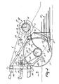
- the plough comprises a frame including two frame beams 1 and 2, which frame beams extend transversely to the direction of operative travel A and are superposed at some interspace. Near each of their ends, the frame beams 1 and 2 are interconnected by an upwardly extending beam 3, the arrangement being such that there is constituted a rectangular framework.
- the ends of the frame beams 1 and 2 and the beam 3 carry an upwardly directed plate 4 which extends into the direction of operative travel A.
- Each of the plates 4 has a lower side which from the lower frame beam 2 extends obliquely downwardly and rearwardly and merges via a short, at least substantually horizontal portion into an obliquely upwardly and rearwardly extending rear side.
- each plate 4 merges into an obliquely upwardly and forwardly extending upper side that ends at the upper frame beam 1.
- a tubular carrier 6 of which the longitudinal centre line, also constituting the rotational axis, extends at least substantially parallel to the frame beams 1 and 2.
- the tubular carrier 6 has a diameter of approximately 30 cms.
- the tubular carrier 6 Near its ends and therebetween at interspaces of, preferably, 60 cms there are mounted on the tubular carrier 6 discs 7 which have a preferred diameter of ⁇ 90 cms and extend at least substantially perpendicular to the longitudinal centre line of the tubular carrier 6. At the circumference, the discs 7 are provided with a cutting edge. As is apparent from Figure 2, behind the discs 7 and at some distance above the lower sides thereof there is arranged between the plates 4 at the level of the horizontal portions between the lower and rear sides thereof a beam 8, which beam extends transversely to the direction of operative travel A. Behind the respective discs 7 there are mounted on the beam 8 at least substantially vertical supports 9. The supports 9 are plate-shaped, their widest sides extending into the direction of operative travel A.
- each of the plate-shaped supports 9 extends concentrically relative to the rotational axis of the tubular carrier 6.
- each of the plate-shaped supports 9 is attached to a beam 10 which extends between the plates 4 parallel to the frame beams 1, 2 and to the beam 8 and is connected to the upper frame beam 1 by means of forwardly and upwardly converging struts 11.
- the beam 8 is provided at its leading side with a forwardly extending, share-shaped member 12, which member has a width that substantially corresponds to the distance between two adjoining discs 7.
- Each share-shaped member 12 extends from the top side of the beam 8 obliquely downwardly, the arrangement being such that its leading side, which, preferably, has an obliquely extending cutting edge, is located at the level of the bottom side of the beam 8 and reaches to below the tubular carrier 6 ( Figure 2).
- Figure 2 With the exception of the, taken in the direction of operative travel A, left support 9, near each left-hand side of a support 9 there is arranged on the top side of the beam 8 a mouldboard-shaped guide member 13 of plate material.
- the mouldboard-shaped guide member 13 is triangular in shape, which triangle has its base attached on the beam 8 and extends from the support 9 in the leading side of the beam 8 obliquely rearwardly.
- the guide member 13 extends from the beam 8 upwardly according to a smooth curve ( Figures 1 and 2).
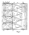
- the supports 9 are provided at their right-hand side with a plurality of plate-shaped elements located above each other at an interspace, the lowermost of said plate-shaped elements being flush with the bottom side of the beam 8 ( Figure 3).
- the plate-shaped elements are decreasing in length, the arrangement being such that the lenght of the topmost plate-shaped element is about equal to at least substantially half that of the lowermost one.
- the plate-shaped elements constitute a mouldboard-shaped guide member 14.
- Each of the plate-shaped elements has a width of ⁇ 60 mms and a thickness of ⁇ 10 mms.
- the plate-shaped elements of a guide member 14 extend from a support 9 obliquely to the, taken in the direction of operative travel A, right-hand side and are at an angle of ⁇ 20° to the said direction of travel.
- the ends of the plate-shaped elements extend into the direction of operative travel A, the end of the lowermost, longest plate-shaped element being located at least substantially near the middle of the space between two adjoining discs 7 ( Figure 1).
- a tubular carrier 16 comprising a plate-shaped, helically extending portion 17.
- the carrier 16 and the portion 17 together constitute a rotationally driven member 18 in the shape of an auger.
- the rotational axis of the rotating member 18 consisting of the tubular carrier 16 and the plate-shaped portion 17 extends transversely to the direction of operative travel A and, as is apparent from Figure 2, is located near the upper sides of the discs 7. Seen in plan view, the said axis is located in front of the middle of the mouldboard-shaped guide member 14 constituted by the plate-shaped elements ( Figure 1).
- the mouldboard-shaped guide members 13 and 14 together constitute a turning means for at least partly turning a furrow slice, which furrow slice is cut loose by means of the discs 7 and the share-shaped members 12 during operation.
- the shafts 15 of the tubular carrier 16 are adjustable in height and are passed through slots provided in each of the plates 4 and are supported by arms 20, which arms 20 extend rearwardly and downwardly along the outer sides of the plates 4 and are pivotable about a drive shaft 21 that extends transversely to the direction of operative travel A.
- the drive shaft 21 is located near the middle between the two frame beams 1, 2 and is accommodated in a tube 22 which extends between the plates 4 and is located parallel to the frame beams 1 and 2.
- each of the arms 20 is provided with a lug 23, through which is passed a pin 24 which can also be passed through one of three superjacent apertures 25 provided in the plates 4, the arrangement being such that the position of the driven member 18 can be altered.
- a pin 24 which can also be passed through one of three superjacent apertures 25 provided in the plates 4, the arrangement being such that the position of the driven member 18 can be altered.
- brackets 26 At the lower side of the beam 10 there are arranged plate-shaped members 27 by means of brackets 26, the downwardly directed ends of which are provided with thread and are adapted to co-operate with nuts.
- the members 27 have a width that corresponds to the distance between two adjoining discs 7 and extend from the beam 10 downwardly via a smooth curve, the leading sides of said members 27 reaching just below the rotational axis of the tubular carrier 6 to as far as the circumference thereof ( Figure 2).
- the members 27 can act as scrapers for scraping soil from the tubular carrier 6.
- a carrier 29 which from the sleeve extends downwardly over some distance and subsequently obliquely downwardly and rearwardly, and whose lower side is provided with a plough body 30 attached thereto.
- a plough body 30 extends obliquely sidewardly at an angle of ⁇ 45°.
- a plough body 30 will move a thin layer of soil to a side, thereby improving the ploughing action of the machine.
- the drive shaft 21 accommodated in the tube 22 is passed through a gear box 31 located near the middle of the tube, in which gear box the shaft 21 is provided with a bevel gearwheel 32 which is adapted to co-operate with a bevel gearwheel 33 on a shaft 34, which shaft 34 projects from the gear box 31 at the front side and can be coupled to the power take-off shaft of a tractor via an intermediate shaft 35.
- the drive shaft 21 projects beyond an arm 20 and is provided with a sprocket wheel 36, around which is laid a chain 37 which is also laid around a sprocket wheel 38 provided on a shaft 5 of the tubular carrier 6 projecting beyond the plate 4.
- the assembly is surrounded by a chain guard 39.
- the drive shaft 21 also projects beyond an arm 20 and is provided with a sprocket wheel 40, around which is laid a chain 41 which is also laid around a sprocket wheel 42 provided on a portion of a shaft 15 of the tubular carrier 16 of the driven member 18, which portion projects beyond the arm 20.
- the assembly is surrounded by a chain guard 43.
- the machine is coupled by means of coupling means constituted by pairs of lugs 44 provided on the frame beams 1 and 2 to the three-point lifting hitch of a tractor, and the shaft 34 projecting from the front side of the gear box 31 is connected to the power take-off shaft of the tractor by means of the intermediate shaft 35.
- the machine In the operating position as shown in Figure 2, the machine is sustaining on the soil by means of the tubular carrier 6 having mounted thereon the discs 7, so that, during travel in the direction indicated by the arrow A, the soil is cut at distances of ⁇ 60 cms by means of the said discs 7.
- the furrow slice as a whole is pushed towards the right under a certain rotation thereof until its right-hand side moves upwardly and gets within the reach of the driven member 18 constituted by an auger, which auger, in view of the rotational direction obtained by the tubular carrier 16 during operation, displaces the upper side of the furrow slice in the opposite direction, i.e. towards the left, the arrangement being such that a turning of the furrow slice is effected and this furrow slice is turned into its own furrow.
- Crop residues can be moved sidewardly by means of the plough bodies 30 arranged near the front side of each of the discs 7, whereafter the whole is compressed by the tubular carrier 6, by means of which the machine is sustaining on the ground during operation.
- the beam 8 and the share-shaped members 12 are located slightly above the lower sides of the discs 7, it is possible to prevent that, when rocks are present in the soil, the share-shaped members 12 will be damaged thereby.
- the driven member 18 which may have any suitable shape, it is possible to adapt the machine to various types of soil, as well as to the desired turning of the furrow slice.
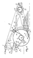
- FIG. 4 A second embodiment of a plough according to the invention is shown in Figures 4 to 6, in which parts corresponding to those in the preceding embodiment have been indicated by the same reference numerals.
- the beam 10 is located between plates 4A which substantially have the same shape as the plates 4 with the exception of a greater length.
- plate-shaped members 45 which, like in the preceding embodiment, have a width that corresponds to the distance between two adjoining discs 7.
- the plate-shaped members 45 extend from the circumference of the discs at least substantially straight ( Figure 5) to as far as the circumference of the tubular carrier 6, for which, as well as for the sides of the discs, they constitute a scraping member.
- each guide member 47 merges into a portion of the support 46.
- the guide member 47 constitutes a segment of a circle ( Figures 4 and 5). As is apparent from the plan view of Figure 4, both the front side and the rear side of the guide member 47 substantially reach to as far as the middle of the space between two discs 7.
- the turning means is constituted by the guide members 14 and 47, the guide members 47 moving the furrow slice sidewardly to the left as well as upwardly and the guide members 14 moving same to the right.
- a roller is arranged freely rotatably by means of shafts 48 and (non-shown) bearings accommodated in bearing housings.
- the roller includes a tubular carrier 50 being provided with cams 51, thereby constituting a packer roller.
- scrapers 52 mounted on a transverse carrier 53 provided between the plates 4A and behind the roller.
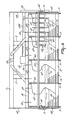
- the machine shown in Figures 4 to 6 operates substantially identically to that of the first embodiment.
- the furrow slice after having been cut by the share-shaped member 12, is urged obliquely rearwardly and upwardly by means of the discs 7, whose rotational direction is indicated in Figure 5.
- the furrow slice is moved towards the right by the guide member 14 located at the left-hand side.
- the right-hand side of the furrow slice is moved upwardly and towards the left by the plate-shaped, mouldboard-shaped guide member 47 at the right-hand side, the arrangement being such that the furrow slice is turned about its longitudinal axis in its own furrow.
- the packer roller 49 can also be driven and has a compacting effect.
- the plough according to the invention is of a comparatively compact construction. With the plough it is possible to turn a furrow slice in its own furrow. By means of the discs 7, the displacement of the furrow slice is supported.
- the power-driven discs have a propulsive effect. Due to this propulsive effect, a comparatively small amount of power will be required for the pulling of the machine through the ground, while, due to the fact that the furrow slice is turned about its longitudinal axis in its own furrow, the field ploughed by such a plough will be furrowless.
- the plough according to the invention may be of a compact construction. Crop residues can be crushed properly by means of the tubular carrier 6, so that the turning of the furrow slices will be improved.
- the plough according to the invention will improve the cutting of the furrow slice at three sides thereof, so that a portion of the turning means can move parts of the furrow slice in one lateral direction and another portion of the turning means can move parts of the furrow slice in an opposite lateral direction in such a way that the field that has been ploughed will be without or almost without furrows.
Landscapes
- Life Sciences & Earth Sciences (AREA)
- Engineering & Computer Science (AREA)
- Mechanical Engineering (AREA)
- Soil Sciences (AREA)
- Environmental Sciences (AREA)
- Soil Working Implements (AREA)
Applications Claiming Priority (2)
| Application Number | Priority Date | Filing Date | Title |
|---|---|---|---|
| NL8802630 | 1988-10-26 | ||
| NL8802630 | 1988-10-26 |
Publications (2)
| Publication Number | Publication Date |
|---|---|
| EP0366202A2 true EP0366202A2 (fr) | 1990-05-02 |
| EP0366202A3 EP0366202A3 (fr) | 1992-01-15 |
Family
ID=19853115
Family Applications (1)
| Application Number | Title | Priority Date | Filing Date |
|---|---|---|---|
| EP19890202678 Withdrawn EP0366202A3 (fr) | 1988-10-26 | 1989-10-24 | Dispositif pour le travail du sol |
Country Status (1)
| Country | Link |
|---|---|
| EP (1) | EP0366202A3 (fr) |
Family Cites Families (6)
| Publication number | Priority date | Publication date | Assignee | Title |
|---|---|---|---|---|
| NL111861C (fr) * | 1960-06-10 | |||
| SE410696B (sv) * | 1978-11-27 | 1979-10-29 | Karlsson Erik Axel Rune | Plog for jordbearbetning |
| NL7906694A (nl) * | 1979-09-07 | 1981-03-10 | Lely Nv C Van Der | Werkwijze voor het ploegen van een strook grond. |
| NL7909235A (nl) * | 1979-12-21 | 1981-07-16 | Lely Nv C Van Der | Ploeg. |
| GB2099673B (en) * | 1981-06-10 | 1984-10-31 | Nat Res Dev | Furrow inverter |
| GB2189672A (en) * | 1986-05-02 | 1987-11-04 | Nat Res Dev | Soil-working assembly |
-
1989
- 1989-10-24 EP EP19890202678 patent/EP0366202A3/fr not_active Withdrawn
Also Published As
| Publication number | Publication date |
|---|---|
| EP0366202A3 (fr) | 1992-01-15 |
Similar Documents
| Publication | Publication Date | Title |
|---|---|---|
| US4538689A (en) | Subsoil plow point | |
| CA2891703C (fr) | Charrue comportant une pluralite de corps de charrue fixes a une barre de charrue | |
| EP0015290A1 (fr) | Systeme de labourage complet a une seule passe | |
| US4267891A (en) | Soil cultivating machines | |
| US4051902A (en) | Soil cultivating implements | |
| US4412587A (en) | Soil working machine | |
| GB2137463A (en) | Soil cultivating machine | |
| DE3854929T2 (de) | Bodenbearbeitungsmaschine mit verbessertem Stabilisierungsorgan | |
| GB2141611A (en) | Soil cultivating implements | |
| US4279311A (en) | High speed tiller with widely spaced discs | |
| US4354557A (en) | Soil cultivating implement | |
| EP0366202A2 (fr) | Dispositif pour le travail du sol | |
| EP0150080A2 (fr) | Machine pour le travail du sol | |
| EP0181039B1 (fr) | Charrue | |
| GB2153192A (en) | A soil cultivating implement with a ground contacting roller assembly | |
| EP0060605B1 (fr) | Machine pour le travail du sol | |
| US4884640A (en) | Soil cultivating implements | |
| GB2127262A (en) | A soil cultivating machine | |
| EP0305601B1 (fr) | Appareil pour cultiver le sol | |
| EP0373711B1 (fr) | Dispositif de travail du sol | |
| EP0262734B1 (fr) | Machine pour le travail du sol | |
| GB2090712A (en) | Soil cultivating equipment | |
| US4189006A (en) | Soil cultivating implements | |
| GB2130463A (en) | A soil cultivating machine | |
| EP0079662B1 (fr) | Machine pour le travail du sol |
Legal Events
| Date | Code | Title | Description |
|---|---|---|---|
| PUAI | Public reference made under article 153(3) epc to a published international application that has entered the european phase |
Free format text: ORIGINAL CODE: 0009012 |
|
| AK | Designated contracting states |
Kind code of ref document: A2 Designated state(s): AT BE CH DE ES FR GB IT LI NL SE |
|
| PUAL | Search report despatched |
Free format text: ORIGINAL CODE: 0009013 |
|
| AK | Designated contracting states |
Kind code of ref document: A3 Designated state(s): AT BE CH DE ES FR GB IT LI NL SE |
|
| 17P | Request for examination filed |
Effective date: 19920702 |
|
| 17Q | First examination report despatched |
Effective date: 19921019 |
|
| STAA | Information on the status of an ep patent application or granted ep patent |
Free format text: STATUS: THE APPLICATION IS DEEMED TO BE WITHDRAWN |
|
| 18D | Application deemed to be withdrawn |
Effective date: 19930430 |