EP0366120B1 - Document conveyance apparatus - Google Patents
Document conveyance apparatus Download PDFInfo
- Publication number
- EP0366120B1 EP0366120B1 EP89119847A EP89119847A EP0366120B1 EP 0366120 B1 EP0366120 B1 EP 0366120B1 EP 89119847 A EP89119847 A EP 89119847A EP 89119847 A EP89119847 A EP 89119847A EP 0366120 B1 EP0366120 B1 EP 0366120B1
- Authority
- EP
- European Patent Office
- Prior art keywords
- document
- platen glass
- conveying
- roller
- axis
- Prior art date
- Legal status (The legal status is an assumption and is not a legal conclusion. Google has not performed a legal analysis and makes no representation as to the accuracy of the status listed.)
- Expired - Lifetime
Links
- 239000011521 glass Substances 0.000 claims description 71
- 238000010586 diagram Methods 0.000 description 14
- 230000003028 elevating effect Effects 0.000 description 14
- 230000002265 prevention Effects 0.000 description 9
- 238000001514 detection method Methods 0.000 description 8
- 238000010276 construction Methods 0.000 description 7
- 238000007599 discharging Methods 0.000 description 7
- 230000006872 improvement Effects 0.000 description 6
- 230000009471 action Effects 0.000 description 5
- 230000002093 peripheral effect Effects 0.000 description 5
- 238000012423 maintenance Methods 0.000 description 4
- 230000007246 mechanism Effects 0.000 description 3
- 238000000034 method Methods 0.000 description 3
- 230000008569 process Effects 0.000 description 3
- 230000009467 reduction Effects 0.000 description 3
- XEEYBQQBJWHFJM-UHFFFAOYSA-N Iron Chemical compound [Fe] XEEYBQQBJWHFJM-UHFFFAOYSA-N 0.000 description 2
- 239000000956 alloy Substances 0.000 description 2
- 229910045601 alloy Inorganic materials 0.000 description 2
- 239000000463 material Substances 0.000 description 2
- 239000004033 plastic Substances 0.000 description 2
- 229920003023 plastic Polymers 0.000 description 2
- 229920000139 polyethylene terephthalate Polymers 0.000 description 2
- 239000005020 polyethylene terephthalate Substances 0.000 description 2
- 238000011144 upstream manufacturing Methods 0.000 description 2
- 238000004804 winding Methods 0.000 description 2
- RYGMFSIKBFXOCR-UHFFFAOYSA-N Copper Chemical group [Cu] RYGMFSIKBFXOCR-UHFFFAOYSA-N 0.000 description 1
- 229920002943 EPDM rubber Polymers 0.000 description 1
- 229920000181 Ethylene propylene rubber Polymers 0.000 description 1
- 230000001174 ascending effect Effects 0.000 description 1
- 230000015556 catabolic process Effects 0.000 description 1
- IYRDVAUFQZOLSB-UHFFFAOYSA-N copper iron Chemical group [Fe].[Cu] IYRDVAUFQZOLSB-UHFFFAOYSA-N 0.000 description 1
- 238000006731 degradation reaction Methods 0.000 description 1
- 230000000694 effects Effects 0.000 description 1
- 239000013013 elastic material Substances 0.000 description 1
- 230000005611 electricity Effects 0.000 description 1
- 230000001747 exhibiting effect Effects 0.000 description 1
- 230000002452 interceptive effect Effects 0.000 description 1
- 229910052742 iron Inorganic materials 0.000 description 1
- 230000009916 joint effect Effects 0.000 description 1
- 238000005461 lubrication Methods 0.000 description 1
- -1 polyethylene terephthalate Polymers 0.000 description 1
- 239000007787 solid Substances 0.000 description 1
- 238000003079 width control Methods 0.000 description 1
- 230000037303 wrinkles Effects 0.000 description 1
Images


Classifications
-
- G—PHYSICS
- G03—PHOTOGRAPHY; CINEMATOGRAPHY; ANALOGOUS TECHNIQUES USING WAVES OTHER THAN OPTICAL WAVES; ELECTROGRAPHY; HOLOGRAPHY
- G03G—ELECTROGRAPHY; ELECTROPHOTOGRAPHY; MAGNETOGRAPHY
- G03G15/00—Apparatus for electrographic processes using a charge pattern
- G03G15/60—Apparatus which relate to the handling of originals
-
- B—PERFORMING OPERATIONS; TRANSPORTING
- B65—CONVEYING; PACKING; STORING; HANDLING THIN OR FILAMENTARY MATERIAL
- B65H—HANDLING THIN OR FILAMENTARY MATERIAL, e.g. SHEETS, WEBS, CABLES
- B65H5/00—Feeding articles separated from piles; Feeding articles to machines
- B65H5/06—Feeding articles separated from piles; Feeding articles to machines by rollers or balls, e.g. between rollers
- B65H5/068—Feeding articles separated from piles; Feeding articles to machines by rollers or balls, e.g. between rollers between one or more rollers or balls and stationary pressing, supporting or guiding elements
-
- G—PHYSICS
- G03—PHOTOGRAPHY; CINEMATOGRAPHY; ANALOGOUS TECHNIQUES USING WAVES OTHER THAN OPTICAL WAVES; ELECTROGRAPHY; HOLOGRAPHY
- G03B—APPARATUS OR ARRANGEMENTS FOR TAKING PHOTOGRAPHS OR FOR PROJECTING OR VIEWING THEM; APPARATUS OR ARRANGEMENTS EMPLOYING ANALOGOUS TECHNIQUES USING WAVES OTHER THAN OPTICAL WAVES; ACCESSORIES THEREFOR
- G03B27/00—Photographic printing apparatus
- G03B27/32—Projection printing apparatus, e.g. enlarger, copying camera
- G03B27/52—Details
- G03B27/62—Holders for the original
- G03B27/6207—Holders for the original in copying cameras
- G03B27/625—Apparatus which relate to the handling of originals, e.g. presence detectors, inverters
-
- G—PHYSICS
- G03—PHOTOGRAPHY; CINEMATOGRAPHY; ANALOGOUS TECHNIQUES USING WAVES OTHER THAN OPTICAL WAVES; ELECTROGRAPHY; HOLOGRAPHY
- G03G—ELECTROGRAPHY; ELECTROPHOTOGRAPHY; MAGNETOGRAPHY
- G03G2215/00—Apparatus for electrophotographic processes
- G03G2215/00172—Apparatus for electrophotographic processes relative to the original handling
- G03G2215/00177—Apparatus for electrophotographic processes relative to the original handling for scanning
- G03G2215/00181—Apparatus for electrophotographic processes relative to the original handling for scanning concerning the original's state of motion
- G03G2215/00185—Apparatus for electrophotographic processes relative to the original handling for scanning concerning the original's state of motion original at rest
Definitions
- the present invention relates to improvement of a document conveyance apparatus according to the preamble of claim 1, which automatically feeds the document onto the document table (platen glass) of a copier, image reading equipment, etc. and discharges the document after processing from such document table.
- the document conveyance apparatus of this type is composed of the document store (paper feeding tray) placed on the side of document table, the document feeding means for feeding the document one by one onto the above document table from such paper feeding tray, the document conveyance means placed on the above document table which conveys the document fed from the above document feeding means, places it correctly on the exposure position on the above document base surface and discharges the document from the above document base upon completion of a prescribed number of exposures, and the paper discharging means which collects the documents, for which exposure has been completed, and places them on the discharging paper tray.
- the document store paper feeding tray
- the document feeding means for feeding the document one by one onto the above document table from such paper feeding tray
- the document conveyance means placed on the above document table which conveys the document fed from the above document feeding means, places it correctly on the exposure position on the above document base surface and discharges the document from the above document base upon completion of a prescribed number of exposures
- the paper discharging means which collects the documents, for which exposure has been completed, and places them on the
- This document conveyance apparatus was provided with the document conveying means for conveying the document by pressing the document against the platen glass surface with white endless belt on the platen glass of a copier and also by movement of such belt.
- this document conveyance means pressed the document by covering the entire surface of the platen glass with the endless belt and simultaneously conveyed it while generating frictional force with appropriate places on the document surface via slight slackness therebetween.
- Applicant of the present invention has earlier improved the above problematic points, and has proposed a document conveyance apparatus which can realize simultaneously reduction in equipment thickness and improvement in maintenance quality (GB-A-2213805).
- the document conveyance apparatus of the present invention is so constructed to have low overall apparatus height and also to permit the document conveyance without use of an endless belt, where the document holding sheet member (white-colored fixing sheet member, hereinafter called the sheet member) is provided along the platen glass surface in the apparatus proper placed above the copier and the document conveyance roller is slidably contacted to the above platen glass surface via perforated holes provided at appropriate places in such sheet member.
- the document holding sheet member white-colored fixing sheet member, hereinafter called the sheet member
- the document conveyance roller in the above document conveyance apparatus consists of a multiple number of rollers for conveying documents of various sizes on the platen glass, and each roller will have the rotating force transmitted thereto from the driving source.
- the document is normally conveyed into the space between the platen glass surface and the document holding sheet by its conveyor, then such document is sent in reverse direction, so that it will run against the stopper board (striking board) for the document rear end, in determining and stopping the document at the correction position, then exposure will be made on the document in such striking and stopping conditions.
- Fig. 21 is a plan view showing the document sizes and the layout of conveying rollers.
- the document of various sizes will stop at the striking board 12 in the extreme left of the document table (platen glass) 11, where the document will have exposure process.
- On the upper surface of the above document table there are provided document conveying rollers 301, 302, 303 and the white-colored sheet member 304 of the document conveyance apparatus.
- the present invention aims at providing the document conveyance apparatus, where all documents of various sizes sent backward will uniformly contact with and certainly stop at the striking board, thereby permitting the document to stop at the correct position, by improvement of the document conveyance apparatus consisting of the above document holding sheet member and the document conveying rollers rotatably driven, in realizing reduction in thickness of the body frame and improvement in maintenance property as well.
- the document conveyance apparatus of the present invention is characterized by having a number of document conveying rollers, in which a number of roller sets are provided to press against the above document table, arranged longitudinally along the document conveying direction, and also by providing a means of separating the conveying rollers, at least other than the document conveying roller set closest to the above striking board, from the document table, and is also characterized by having a construction where a spring clutch is built-in on the driving axis of conveying rollers and such driving axis is moved against the spring force, thereby separating the above document conveying rollers from the document table and driving thereof, by having a construction where a wire is connected to the driving axis of the
- Fig. 1 shows a sectional view of the document conveyance apparatus of the present invention
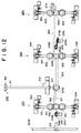
- Fig. 2 an overall driving system diagram of this document conveyance apparatus
- Fig. 3 a perspective view of the conveying roller driving system
- Fig. 4 a perspective view showing layout of the white-colored sheet member and document conveying rollers
- Fig. 5 a plan view of each part of conveying rollers in Embodiment 1
- Fig. 6 a sectional view of the conveying driver in Embodiment 1
- Fig. 7 a sectional view of the conveying roller in Embodiment 1
- Fig. 8 and Fig. 10 sectional views of elevating means for conveying rollers in Embodiment 1, Fig. 9 and Fig.
- FIG. 11 side views showing elevating and rotating of conveying rollers in Embodiment 1
- Fig. 12 a plan view of conveying mechanism in Embodiment 2 in the document conveyance apparatus of the present invention
- Fig. 13 and Fig. 14 schematic illustrations which explain operating conditions of each conveying roller in Embodiment 2
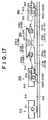
- Fig. 15 a plan view of the conveying roller driving system in Embodiment 3
- Fig. 16 and Fig. 19 side views of the conveying roller driving system in Embodiment 3
- Fig. 17 and Fig. 20 side views of the conveying roller elevating means in Embodiment 3
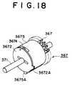
- Fig. 18 a perspective view of the spring clutch
- Fig. 21 a plan view showing document sizes and conveying roller layout.
- Fig. 1 shows a sectional view of the document conveyance apparatus of the present invention
- Fig. 2 an entire driving system of this document conveyance apparatus
- Fig. 3 a perspective view of the conveying roller driving system
- Fig. 4 a perspective view of white-colored sheet member and conveying rollers
- Fig. 5 a plan view showing driving mechanism of conveying rollers.
- 10 is the copier proper, 11 the platen glass (document table), 12 the document rear end stopper (striking board), and the document conveyance apparatus 100 is mounted above the platen glass 11.
- Such document conveyance apparatus 100 is of shakable construction, being attached to the hinge above the copier proper 10, permitting opening or closing of the upper surface of platen glass 11.
- the above document conveyance apparatus 100 consists of the three principal parts, namely, paper feeder 200, conveyor 300 and paper discharger 400.
- the paper feeding tray consisting of the movable paper feeding plate 102, which is foldable, and the fixed paper feeding plate 103, which is firmly attached to the housing proper 101, both of which are installed with an inclination.
- Document D can be loaded on such paper feeding tray in layers, and the end of document D can be inserted into the paper feeder 200.
- the paper width control boards 104 there are provided the paper width control boards 104, movable in width direction, so as to control the lateral width in setting the document D.
- the feeding lever 201 is shakably supported on top of the above movable guide board.
- the axis at one end of the feeding lever 201 is rotatably supported by axis on top of the paper feeder outlet 106 of the housing proper 101, and the other end descends due to own weight of the feeding lever 201, thereby pressing upper surface of the document D.
- Fig. 1 is a sectional view showing this document setting condition.
- the movable guide board 105 When the above solenoid is supplied with electricity by the starting signal of paper feeding, the movable guide board 105 is shaked and its forward end falls and starts descending from the upper surface of the above fixed paper feeding plate 103.
- the paper feeder 200 installed on the feeding downstream side of the above paper feeding tray is provided with the sending means (No. 1 paper feeding means) for sending a bundle of document D inserted from the paper feeding tray and, further, for sending such document, by separating each sheet from the lowest layer, and also with the No. 2 paper feeding means of feeding the document D onto the platen glass 11 of the copier proper 10.
- the sending means No. 1 paper feeding means
- This sending means consists of the sending roller (No. 1 paper feeding roller) 212, which is rotatably inserted in the center of No. 1 driving axis 210 and is driven by No. 2 driving axis 211, and the double-feeding prevention roller 213, which is axially supported by the double-feeding prevention roller attachment board 214, installed in diagonally upper direction of such sending roller 212.
- Fig. 2 is the driving system diagram for the entire document conveyance apparatus.
- Driving axis of the main motor 215 rotates the above No. 2 driving axis 211 via gears 216 and 217, timing pulleys 218 and 219 and timing belt 220, gear 221 which is coaxial with the timing pulley 219 and gear 222 which is integral with No. 2 driving axis 211.
- gear 224 At one end of such No. 2 driving axis 211 there is provided gear 224 which has one-direction clutch 223 built therein. This gear 224 engages with gear 225 which is integral with the sending roller 212, rotatably inserted in the above No. 1 driving axis 210.
- No. 2 paper feeding rollers 226, 226 are fixed on the axis, thereby rotating integrally with the driving axis.
- gear 230 is fixed on the axis, and such gear 230 engages with gear 227 at the axis tip of the above No. 1 driving axis 210.
- No. 1 driving axis 210 and No. 2 paper feeding rollers 226, 226 integral thereto make a fixed rotation always in the direction of paper feeding, with respect to normal and reverse rotation of the main motor 215.
- Gear 229 fixed on the axis of the above No. 1 driving axis 210 is transmitting power to No. 3 driving axis (torque limiter axis) 234 having gear 233 fixed at one tip thereof, via idler gear 232.
- gear 236 having torque limiter 235.
- Such gear 236 engages with gear 238 which is integral with the above double-feeding prevention roller 213 via idler gear 237.
- Double-feeding prevention roller 213 forms a nip, being pressure contacted to the above sending roller 212 at a prescribed pressure.
- the above No. 1 driving axis 210 makes rotation in the fixed direction, regardless of the normal or reverse rotation of the main motor 215, and it is also possible to have rotation in the fixed direction for the double-feeding prevention roller 213 coupled thereto via gears.
- No. 2 paper feeding means in the paper feeding means 200 consists of two No. 2 paper feeding rollers 226, 226 fixed on both sides of the above sending roller 212, rotatably inserted in the above No. 1 driving axis 210, and the driven roller 240 pressure contacted on the lower side of such rollers 226, 226, capable of being rotatably driven by such rollers.
- No. 2 paper feeding rollers 226, 226 can be driven independently from the sending roller 212, and, further, when the sending roller 212 rotates, they will rotate in the same direction, thereby not interfering with the sending of document D.
- a document detection sensor 241 on the conveyance path in the downstream of feeding from the nip position between the above sending roller 212 and double-feeding prevention roller 213 and close to the pressure contacting position of the above driven roller 240.
- Such document detection sensor 241 is so arranged to be turned ON when forward end of one document, separated and sent at the nip position, among the above bundle of documents passes, to be turned and OFF when the rear end thereof passes.
- No. 1 driving axis 210 at this time will still continue rotation in the same direction, and No. 2 paper feeding roller 226, fixed on the axis of such axis 210, will also continue rotating in the same direction, via gear 230 of No. 2 driving axis 211, idler gear 232, gear 227 which has one-direction clutch built therein (but rotation is not transmitted to the gear 228 which has the above one-direction clutch built therein).
- No. 2 driving axis 211 will also shift from reverse rotation to normal rotation, but gear 224 will become free rotation by the one-direction clutch 223 provided at the axis tip of such No. 2 driving axis 211, and rotation will not be transmitted to any of gear 225 engaging thereto and sending roller 212 integral with gear 225.
- double-feeding prevention roller 213 acts to prevent double-feeding of the document in the second sheet and thereafter and to return thereof by continuously making normal rotation, since No. 1 driving axis 210 maintains normal rotation. Additionally, No. 2 paper feeding roller 226 will continue its rotation thereafter and will continuously feed the separated one sheet of document D to conveyor 300.
- Conveyor 300 is for the purpose of conveying document D on platen glass 11, and is provided with white-colored sheet member 304 and document conveying rollers 301, 302 and 303 as principal elements.
- White-colored sheet member 304 (hereinafter called the sheet member) is for the purpose of pressuring document D at the time of exposure and is made of plastic material (PET: polyethylene terephthalate in the present embodiment) which is rich in solid lubrication property, and this covers the entire upper surface of platen glass.
- PET polyethylene terephthalate in the present embodiment
- Left end 304a of the above sheet member 304 on the side of paper feeder 200 is attachably fixed in the bend of sheet stopping board 361. Protruded both ends of such sheet stopping board 361 are fixed to the frame proper of paper feeder 200 with screws.
- right end 304b of the above sheet member 304 on the side of paper discharger 400 is attachably fixed in the bend of the other sheet stopping board 362.
- Center of such sheet stopping board 362 is connected to the fixed portion of conveyor 300 with pressure of a coil spring, which is not shown in the diagram.
- perforated holes 305, 306 and 307 through which tips of document conveying rollers 301, 302 and 303 are made to protrude.
- Document conveying rollers 301, 302 and 303 are for the purpose of conveying document D on platen glass 11, and are provided to correspond with each perforated holes 305, 306 and 307 on the back surface side of sheet member 304, so as to convey document D by frictional force under pressure while rotating, through perforated holes 305, 306 and 307.
- Surface of such rollers 301, 302 and 303 are covered by an elastic material having large frictional force (for example, foamed material of EPDM rubber ethylene-propylene rubber or plastics), and its tip contacts with the surface of platen glass through perforated holes 305, 306 and 307.
- document conveying rollers 301, 302 and 303 can make both normal and reverse rotation, so as to permit fine adjustment for final position of document D at the time of exposure.
- Sheet member pressuring means 360 is for the purpose of improving exposure conditions by closely contacting the sheet member 304 onto platen glass 11 at the time of exposing the document and also of making smooth conveyance of document by raising the sheet member from the surface of platen glass 11 at the time of conveying the document. Unless pressuring force is applied on sheet member 304, it is so arranged that such sheet member 304 is raised upward.
- Such pressuring means 360 consists of pressuring board 360A (swing back board) and pressuring driving axis 360B.
- Pressuring board 360A is co-axial with the sheet member 304, so as to permit pressuring of the above sheet member 304 against the striking board with uniform force, and is of elastic member, having a protruding curved surface on the contacting side with sheet member 304.
- End of the pressuring driving axis 360B is connected to the main motor 215 via a series of gears, from which driving is transmitted to the axis. (Refer to swing back board “E” in Fig. 2.) There is provided a torque limiter at the end of the above pressuring driving axis 360B, and when the above pressuring board 360A contacts with the striking board, it will act to maintain the contacting condition and also to eliminate undue load.
- the above main motor 215 drives the above paper feeder 200 and conveyor 300 simultaneously. That is to say, gear 216 which is integral with main motor 215 is connected to the conveying driver 310 via a series of gears, thereby rotatably driving the driving axis (station axis) 311.
- Fig. 6 is a sectional view of the above conveying driver 310.
- the above driving axis 311 is supported rotatably at its axis by bearings 312 and 313 close to both ends of the axis as well as by the attachment boards 314 and 315, which fix such bearings 312 and 313. Further, at one end of such driving axis 311 there is fixed the gear 316, and close to the other end there is fixed the pulley 317.
- Such gear 316 engages with freely-rotatable gear 320, having a small diameter, on the idler axis 319 fixed to the attachment board 318.
- Such small-diameter gear 320 is integral with large-diameter gear 321, and such gear 321 engages with gear 216, which is integral with driving axis of the above main motor 215.
- main motor 215 is transmitted via a series of gears 216, 321, 320 and 316, thereby rotating the driving axis 311.
- Timing pulley 317 installed at end of driving axis 311 has geared pulley at two places on both ends, and they are respectively rotatable for winding the timing belts 322, 323.
- timing pulley 332 integrally fixed on the axis.
- Such bearings 333, 333 are respectively inserted into the longitudinal hole of the forward and rear conveying roller attachment boards 334, 334, and their rotation will be stopped by the notch.
- Rotating axis 301 of the above document conveying roller 301 is inserted into the above attachment boards 334, 334 together with bearings 333, 333.
- Bearings 333, 333 at both ends of rotating axis 301 will be spring energized by torsion springs 335, 335, thereby pressuring the outer peripheral surface of document conveying roller 301 against the surface of platen glass 11.
- No. 1 conveying roller 330 as constructed above is pressured against platen glass 11, and will simultaneously have driving transmitted thereto by the timing belt 322, which is wound on the timing pulleys 317, 331.
- Fig. 7 is a sectional view of No. 2 conveying roller 340.
- Document conveying roller 302 of No. 2 conveying roller 340 will be similarly spring energized by torsion springs 345, 345, thereby pressuring the outer peripheral surface of document conveying roller 302 against the surface of platen glass 11. Further, by rotation of the timing belt 323 the timing pulley 342 rotates, thereby transmitting such rotation.
- No. 3 conveying roller 350 consists of members common with those for No. 2 conveying roller 340. That is to say, driving force of the above timing pulley 342 and timing belt 324 is received with timing pulley 352, and it rotates integrally with such timing pulley 352. Tensioned spring force will pressure the conveying roller, in the same manner as before, thereby pressuring against the platen glass 11.
- No. 2 conveying roller 340 as representative example.
- Document conveying roller 302 consists of bush member 3022 fixed to rotating axis 341 with pin and elastic member 3021 covering the outer periphery of such bush member 3022.
- Fig. 8 shows a sectional view of elevating driving means of conveying rollers 302 and 303 at the time of normal sending of document
- Fig. 9 a side view of each position and rotational driving of conveying rollers 301, 302 and 303 in conveyor 300 at the time of normal sending of document.
- bearings 343, 343 which support both ends of rotating axis 341 will descend toward platen glass 11 along inner wall of the longitudinal holes of the above conveying roller attachment boards 344, 344, and will stop descending by coming into contact with the surface of platen glass 11.
- document conveying roller 303 in No. 3 conveying roller 350 will also descend and come into contact with platen glass 11.
- each member in the conveying roller driver will rotate in the direction of arrow mark shown in Fig. 8 and Fig. 9 by the driving force of main motor 215, and protrusions 347a and 357a in spring clutches 347 and 357 will rotate in counterclockwise direction, and will stop by coming into contact with stoppers 349a, 359a.
- Conveying roller driver will continue rotating in the above direction of arrow mark by driving force of main motor 215. While clutch member 347 will stop, the rotating axis 341 and document conveying roller 302 integral therewith will continue rotation and driving.
- Document conveying roller 303 in No. 3 conveying roller 350 will similarly pressure against platen glass 11 and will rotate and drive in counterclockwise direction. Further, since only No. 1 conveying roller 330 does not have spring clutch, it will always rotate and drive in pressuring against platen glass 11.
- document conveying rollers 301, 302 and 303 will all pressure against platen glass 11 and rotate and drive in counterclockwise direction, thereby normally conveying document D in the direction of arrow mark.
- Fig. 10 is a sectional view of elevating driving means of conveying rollers 302 and 303 at the time of reverse sending of document
- Fig. 11 a side view of each position and rotational driving of conveying rollers 301, 302 and 303 in conveyor 300 in reverse sending condition of document.
- each of document conveying roller 301, 302 and 303 in each of conveying rollers 330, 340 and 350 will all at once rotate in the direction of arrow mark (rotation in clockwise direction) as shown in Fig. 10 and Fig. 11.
- clutch member 347 of No. 2 conveying roller 340 will initially rotate in clockwise direction together with rotating axis 341, being pressured by torsion spring 348, when its protrusion 347a comes into contact with stopper 349b, the rotation will stop, by having the movement obstructed, and it will rotate idly by having relative friction with collar 346 which is fixed to the rotating axis 341, which rotates being driven.
- conveying roller 303 will also be pushed upward, and will be separated from the surface of platen glass 11.
- conveying roller 301 of No. 1 conveying roller 330 is always rotationally driven in pressing against platen glass 11
- conveying rollers 302 and 303 will retreat upward and conveyance under pressure will be made only by conveying roller 301, at the time of sending document in reverse direction.
- main motor 215 is again switched to reverse rotation, where each rotating axis 331, 341 and 351 will make counterclockwise rotation as shown in Fig. 8 and Fig. 9, and document conveying rollers 302 and 303 will make driving rotation while pressing against the surface of platen glass 11.
- Fig. 12 is a plan view of the conveyor of document conveyance apparatus under Embodiment 2 of the present invention
- Fig. 13 and Fig. 14 are schematic diagrams in explaining elevating of document conveying rollers. Further, in these diagrams, portions having the same functions as those in the above embodiment will be denoted by the same number. Further, explanations will be made on points which are different from the above embodiment.
- Conveyor 300 consists of the conveying driver 310 which transmit driving force of main motor 215 to document conveying rollers 301, 302 and 303, No. 1 conveying roller 330 which supports document conveying roller 301 close to the striking board 12, No. 2 conveying roller 340 which supports the middle document conveying 302, No. 3 conveying roller 350 which supports document conveying roller 303 close to the paper discharger 400, and the roller elevating means 370 which acts to elevate the above document conveying rollers 302 and 303 by wire.
- the conveying driver 310 and No. 1 conveying roller 330 have almost identical construction with the above embodiment, and explanations on the construction and functions concerning No. 2 and No. 3 conveying rollers 340 and 350 are to be omitted.
- V-shaped groove 3170 is formed in the central drum of timing pulley 317 in conveying driver 310, to which wire 371, to be described later, will be hung. Further, V-shaped grooves 3420 and 3520 of the same form as above are respectively formed in each central drum of timing pulleys 3420 and 3520 in No. 2 and No. 3 conveying rollers 340 and 350.
- Flap board 372 is fixed to the pressure driving axis 360B of the above sheet pressing means 360, on the side close to paper feeder 200, and one end of wire 371 is fixed at the tip of such flap board 372.
- Guide roller 374 is freely rotatable, being supported by the supporting board 3741 and guide pin 3742.
- Tension roller 375 is supported by supporting board 3751, shaking lever 3752 and pin 3753, and is freely movable and rotatable to flip by the tension of spring 3754.
- the above wire 371 is held by the flip board 372 at its left end and is held by the terminal fixing member 373 at its right end, and is suspendedly hung, being pressured, in its middle portion, by V-shaped groove 3740 of guide roller 374, V-shaped groove 3170 on the axis of conveying driver 310, V-shaped groove 3420 on the same axis as document conveying roller 302, V-shaped groove 3750 of tension pulley 375 and V-shaped groove 3520 on the same axis as document conveying roller 303.
- Fig. 13 is a schematic diagram showing actions of the conveyor 300, when document D is normally conveyed in the direction of arrow mark.
- the document conveying roller 301, 302 and 303 are driven and rotated in counterclockwise direction.
- the pressure driving axis 360B of sheet pressuring means 360 will also be driven in counterclockwise direction, and the pressure board (swing back board) 360A fixed to such pressure driving axis 360B will move to the upper position shown with a solid line, thereby facilitating document conveyance by not pressuring sheet member 304 and making it free.
- document conveying rollers 301, 302 and 303 are made to rotate in clockwise direction by switching driving axis 311 in reverse, and simultaneously pressure driving axis 360B will rotate in counterclockwise direction and flap board 372 fixed to such axis will also shake in counterclockwise direction, thereby lowering the wire 371.
- wire 371 will raise conveying rollers 302 and 303 upward, in resisting the tensioned spring force, via guide roller 374 and V-shaped groove 3170 on driving shaft, thereby forming gap S between upper surface of platen glass 11 and lower peripheral surface of document conveying rollers 302 and 303.
- pressuring board 360A will also descend and also press against the striking board 12 via sheet member 304, thereby shutting the space above the striking board 12.
- Fig. 15 is a plan view of the conveyor of document conveyance apparatus under Embodiment 3 of the present invention
- Fig. 16, Fig. 17, Fig. 19 and Fig. 20 are schematic diagrams for explaining elevating of document conveying roller
- Fig. 18 a perspective view of spring clutch. Further, in these figures portions having the same functions as those in Embodiments 1 and 2 will be denoted by the same number. Further, points different from Embodiments 1 and 2 will be explained.
- Driving rotational force of main motor 215 is transmitted via a series of gears 216, 321, 320 and 316 and rotates the driving axis 311, in the same manner as in the above two embodiments.
- Timing pulley 317 fixed at axis end of driving axis 311 has geared pulley at 2 places in both ends, which are rotatable by winding timing belts 322 and 323 respectively.
- Such bearings 342A and 342B are respectively inserted in the longitudinal hole of front and rear conveying roller attachment board 343 respectively, and their rotation is stopped at the notch.
- Rotating axis 302a of the above document conveying roller 302 is inserted in the above attachment board 343 together with bearings 342A and 342B.
- Bearings 342A and 342B will contact the outer periphery of document conveying roller 302 with surface of platen glass 11 under pressure, being spring energized.
- No. 1 conveying roller 330 not shown in diagram, which is constructed in the same manner as No. 2 conveying roller, will have driving transmitted thereto by the timing belt 322, which is wound on timing pulleys 317, 331, while being pressed against platen glass 11.
- Document conveying roller 302 of No. 2 conveying roller 340 while being spring energized in the similar manner, will have rotation transmitted thereto with rotation of the timing pulley 341, by rotation of the timing belt 323.
- 342A and 342B are bearings which rotatably support both ends of conveying roller 303 and which can move in vertical direction, being inserted in the long hole of attachment board 343, and they are pressured against platen glass 11 by torsion spring 344.
- Document conveying roller 303 of No. 3 conveying roller 350 receives driving force of the above timing pulley 341 and timing belt 324 with timing pulley 351, and rotates integrally with such timing pulley 351. Spring energized force will pressure the conveying roller, in the same manner as before, thereby pressing against the platen glass 11.
- 352A and 352B are bearings which rotatably support both ends of conveying roller 302 and which can move in vertical direction, being inserted in the long hole of attachment board 353, and they are pressured against platen glass 11 by torsion spring 354.
- Fig. 16 is a side view of rotational driving means of conveying rollers 302 and 303, showing document conveying condition and Fig. 17 a side view of elevating driving means of such conveying rollers 302 and 303.
- timing pulley 361 integrally formed therewith, which is wound to the other timing pulley 363 by timing belt 362.
- Such timing pulley 363 forms one body with gear 364 and rotatable around the supporting axis placed on the supporting base board 366.
- the above gear 364 engages with gear 3671 in spring clutch 367 provided at one end of the cam axis 371, to be described later.
- Such cam axis 371 is rotatably supported by bearing 368 fixed to the above supporting base board 366 and by bearings 372A and 372B provided in supporting board 374 of the conveying roller elevating means 370, to be described later.
- Fig. 18 is a perspective view of spring clutch 367.
- spring clutch 367 consists of hub 3672 fixed to cam axis 371, the above gear 3671, which is freely rotatable, being integral with sliding bearing which fit into cam axis 371, coil spring 3674, which is freely tightened or loosened, being wound to each drum of such gear 3671 and hub 3672, and collar 3675 which ties one end of such coil spring and covers coil spring.
- Protrusion 3672A is formed on a part of the periphery of the above hub 3672, and rotation of hub 3672 will stop, when such protrusion 3672A comes into contact with one tongue 369A of the stopper 369, fixed to supporting base board 366.
- protrusion 3675A on a part of the periphery of collar 3675, and rotation of collar 3675 will stop, when such protrusion 3675A comes into contact with the other tongue 369B of the above stopper 369.
- the above flap levers 377A and 377B are respectively spring energized by coil springs 376A and 376B, thereby shaking in counterclockwise direction, centering around the above supporting axes 375A, 375B, raising right end (refer to Fig. 17) of each flap lever 377A and 377B and contacting with eccentric cams 373A, 373B under pressure.
- left end of flap levers 377A and 377B descends, and conveying roller 302 of No. 2 conveying roller 340 descends along the long hole of attachment board 343, by tensioned spring force of torsion spring 344 as well as its own weight, and comes into contact with the upper surface of platen glass 11, pressuring thereon.
- the other flap levers 377C and 377D are respectively energized by coil springs 376C and 376D, thereby shaking in counterclockwise direction, centering about the above supporting axes 375A and 375B, raising left end (refer to Fig. 8) of each shaking levers 377C and 377D and contacting with the eccentric cams 373C, 373D under pressure.
- right end of such flap levers 377C and 377D descends, and conveying roller 303 of No. 3 conveying roller 350 descends along the long hole of attachment board 353, by tensioned spring force of torsion spring 354 as well as its own weight, and comes into contact with the upper surface of platen glass 11, pressuring thereon.
- the document on platen glass 11 is conveyed by driving rotation under pressure, in conditions where the above conveying rollers 302 and 303 are in descent state.
- each member of conveying roller driver rotates in the direction of arrow mark shown in Fig. 16 by driving force of the main motor 215, hub 3675 of spring clutch 367 rotates in counterclockwise direction, and protrusion 3675A stops by coming into contact with tongue 369B of stopper 369.
- This hub 3675 of spring clutch 367 rotates as one body with cam axis 371, being pin connected thereto, and cams 373A and 373B will stop, when reaching the upper dead point shown in Fig. 17.
- Conveying roller driver continues to rotate in the direction of the above arrow mark by driving force of main motor 215. While gear 3671 of spring clutch 367 is also rotating continuously, depending on the degree of loosening in coil spring 3674, which is built in spring clutch 367, it will rotate idly with sliding bearing 3673, thus the driving force will not be transmitted to cam shaft 371.
- the main motor 215 When this pulse number is counted up, the main motor 215 will have its rotation changed from reverse to normal, and conveying rollers 301, 302 and 303 will rotate in reverse direction and make the rear end of document D to contact with the striking board 12, thereby placing document D in the prescribed position on the platen glass 11.
- Fig. 19 is a side view of rotational driving means of conveyor 300 in document reverse sending condition
- Fig. 20 a side view of elevating driving means of conveying rollers 302 and 303 at the time of document reverse sending.
- each member of conveying roller driver will rotate in the direction of arrow mark shown in Fig. 19, and gear 3671 of spring clutch 367 rotates in clockwise direction, thereby integrally rotating hub 3672, which is spring connected to such gear via coil spring 3674.
- Protrusion 3672A of hub 3672 rotates in reverse direction and comes into contact with tongue 369A of the above stopper 369, and hub 3672 stops.
- cam axis 371 integral with hub 3672 will also stop after rotating in reverse direction, and cams 373A and 373B come to the lower dead point shown in Fig. 20.
- the above gear 3671 continues to rotate in reverse direction by normal driving force of the above main motor 215, even after hub 3672 stopped, depending on the slackening condition of coil spring 3674.
- flap levers 377A and 377B will flip, centering around supporting axes 375A and 375B respectively, being pressured by such cams 373A and 373B, and ends of flap levers 377A and 377B will pressure against and push up bearings 342A and 342B, inserted into both ends of conveying roller 302, thereby separating conveying roller 302 from the surface of platen glass 11.
- flap levers 377C and 377D will also be flaped by the above cams 373A, 373B, and thereby separating conveying roller 303 from the surface of platen glass 11.
- conveying roller 301 of No. 1 conveying roller 330 is always driven rotatably, pressuring against platen glass 11, it is pressure conveyed only by conveying roller 301 at the time of conveying document, regardless of document size.
- the sheet member 304 will pressure contact document D to platen glass 11, and exposure scanning and image forming process of the document will be started consecutively within the copier proper 10.
- Document D for which exposure scanning has been completed, passes above platen glass 11 by pressured rotation of conveying rollers 301, 302, and 303, is discharged being held with pressure by paper discharging roller 401 of paper discharger 400 and pinch rollers 402, 403, and is placed above the paper discharging plate 406, which is located outside.
- paper discharging sensor 404 When the front end or rear end of document D is detected by paper discharging sensor 404, placed in the conveying path of the above paper discharger 400, paper feeding actions for second and subsequent sheets will be repeated in the same manner as described above.
- the document conveyance apparatus of the present invention is a document conveyance apparatus of roller conveying type, which has realized reduction in equipment thickness and improvement in maintenance quality, in each of Embodiments 1, 2 and 3.
- document is conveyed by reverse driving by at least one set of conveying rollers closest to the striking board, among a number of conveying rollers. Since other rollers are separated from the surface of platen glass, the document being sent in reverse direction will be sent smoothly in reverse direction always by a constant conveying force, regardless of the document size.
- elevating means of conveying rollers does not require an exclusive power source and construction of conveyor is simple, thereby exhibiting excellent effects in realizing low cost and improvement of reliability.
Description
- The present invention relates to improvement of a document conveyance apparatus according to the preamble of
claim 1, which automatically feeds the document onto the document table (platen glass) of a copier, image reading equipment, etc. and discharges the document after processing from such document table. - Generally, the document conveyance apparatus of this type is composed of the document store (paper feeding tray) placed on the side of document table, the document feeding means for feeding the document one by one onto the above document table from such paper feeding tray, the document conveyance means placed on the above document table which conveys the document fed from the above document feeding means, places it correctly on the exposure position on the above document base surface and discharges the document from the above document base upon completion of a prescribed number of exposures, and the paper discharging means which collects the documents, for which exposure has been completed, and places them on the discharging paper tray.
- This document conveyance apparatus was provided with the document conveying means for conveying the document by pressing the document against the platen glass surface with white endless belt on the platen glass of a copier and also by movement of such belt. In other words, this document conveyance means pressed the document by covering the entire surface of the platen glass with the endless belt and simultaneously conveyed it while generating frictional force with appropriate places on the document surface via slight slackness therebetween. On account of the above arrangement, there were the following problematic points:
- 1 Space in the thickness direction became necessary to allow for the belt rotation, thereby increasing the height of the equipment proper, and the equipment became large.
- 2 Maintenance quality was not satisfactory because of lowering of the pressing force with the passage of time due to fatigue or degradation of the belt and also because of frequent troubles due to lack in elasticity.
- 3 A large-sized motor of high output had to be used, because the belt was rotated while sliding it on the platen glass.
- Applicant of the present invention has earlier improved the above problematic points, and has proposed a document conveyance apparatus which can realize simultaneously reduction in equipment thickness and improvement in maintenance quality (GB-A-2213805).
- The document conveyance apparatus of the present invention is so constructed to have low overall apparatus height and also to permit the document conveyance without use of an endless belt, where the document holding sheet member (white-colored fixing sheet member, hereinafter called the sheet member) is provided along the platen glass surface in the apparatus proper placed above the copier and the document conveyance roller is slidably contacted to the above platen glass surface via perforated holes provided at appropriate places in such sheet member.
- The document conveyance roller in the above document conveyance apparatus consists of a multiple number of rollers for conveying documents of various sizes on the platen glass, and each roller will have the rotating force transmitted thereto from the driving source.
- In this document conveyance apparatus, the document is normally conveyed into the space between the platen glass surface and the document holding sheet by its conveyor, then such document is sent in reverse direction, so that it will run against the stopper board (striking board) for the document rear end, in determining and stopping the document at the correction position, then exposure will be made on the document in such striking and stopping conditions.
- Fig. 21 is a plan view showing the document sizes and the layout of conveying rollers. In the diagram, the document of various sizes will stop at the
striking board 12 in the extreme left of the document table (platen glass) 11, where the document will have exposure process. On the upper surface of the above document table there are provideddocument conveying rollers colored sheet member 304 of the document conveyance apparatus. - However, in such document conveyance apparatus, when a document is conveyed toward the striking board on the document table, in the case of a document of the smallest size, for example, B6 size or B5 size document, such document will be conveyed under pressure contact, being slidably moved by one set of the document conveying rollers closest to the striking board, and in the case of a document of the largest size, for example, A3 size document, such document will be conveyed under pressure contact, being slidably moved by a number of document conveying roller sets.
- In this manner, with respect to documents of each size which are run against the striking board, in the case of a document of small size, its striking force will be small, being run and stricken only by the sliding conveying force of one set of the document conveying rollers closest to the striking board, and in the case of a document of medium size and in the case of a document of large size, they are run and stricken by the sliding conveying force of 2 sets or 3 sets of the document conveying rollers. Therefore, the striking force of medium size documents and large size documents against the striking board will become large proportionately with the number of roller sets.
- At the time of sending the document backward and stopping it at the striking board, when the striking force of the document by each document conveying roller is excessive, the rear end of the document may be folded, wrinkles may be generated in the document, or the document may be set diagonally. Alternately, there may arise such troubles, where rear end of the document rides on the upper surface of the striking board or the document further passes above the striking board and returns to the paper feeder side.
- In consideration of the above described points, the present invention aims at providing the document conveyance apparatus, where all documents of various sizes sent backward will uniformly contact with and certainly stop at the striking board, thereby permitting the document to stop at the correct position, by improvement of the document conveyance apparatus consisting of the above document holding sheet member and the document conveying rollers rotatably driven, in realizing reduction in thickness of the body frame and improvement in maintenance property as well.
- In order to accomplish the above purpose, in the document conveyance apparatus consisting of the document conveying rollers, which convey the document fed from the paper feeding means in normal direction on the document table of the copier and which also convey such document in reverse direction so as to contact against the striking board, and also of the document holding sheet member, which presses the document against the document table surface, the document conveyance apparatus of the present invention is characterized by having a number of document conveying rollers, in which a number of roller sets are provided to press against the above document table, arranged longitudinally along the document conveying direction, and also by providing a means of separating the conveying rollers, at least other than the document conveying roller set closest to the above striking board, from the document table, and is also characterized by having a construction where a spring clutch is built-in on the driving axis of conveying rollers and such driving axis is moved against the spring force, thereby separating the above document conveying rollers from the document table and driving thereof, by having a construction where a wire is connected to the driving axis of the conveying rollers, at least other than the document conveying roller set closest to the above striking board, such wire being moved correspondingly with the pressed driving of the above document holding sheet member, thereby driving the above document conveying rollers, being separated from the document table, and also by having a construction where the conveying rollers, at least other than the document conveying roller set closest to the above striking board, are attached to the elevating means having a freely rotatable supporting board, thereby separating the above document conveying rollers from the document table and driving thereof.
- Fig. 1 shows a sectional view of the document conveyance apparatus of the present invention, Fig. 2 an overall driving system diagram of this document conveyance apparatus, Fig. 3 a perspective view of the conveying roller driving system, Fig. 4 a perspective view showing layout of the white-colored sheet member and document conveying rollers, Fig. 5 a plan view of each part of conveying rollers in
Embodiment 1, Fig. 6 a sectional view of the conveying driver inEmbodiment 1, Fig. 7 a sectional view of the conveying roller inEmbodiment 1, Fig. 8 and Fig. 10 sectional views of elevating means for conveying rollers inEmbodiment 1, Fig. 9 and Fig. 11 side views showing elevating and rotating of conveying rollers inEmbodiment 1, Fig. 12 a plan view of conveying mechanism in Embodiment 2 in the document conveyance apparatus of the present invention, Fig. 13 and Fig. 14 schematic illustrations which explain operating conditions of each conveying roller in Embodiment 2, Fig. 15 a plan view of the conveying roller driving system in Embodiment 3, Fig. 16 and Fig. 19 side views of the conveying roller driving system in Embodiment 3, Fig. 17 and Fig. 20 side views of the conveying roller elevating means in Embodiment 3, Fig. 18 a perspective view of the spring clutch, and Fig. 21 a plan view showing document sizes and conveying roller layout. - Hereinafter, embodiments of the present invention are explained according to the attached diagrams.
- Fig. 1 shows a sectional view of the document conveyance apparatus of the present invention, Fig. 2 an entire driving system of this document conveyance apparatus, Fig. 3 a perspective view of the conveying roller driving system, Fig. 4 a perspective view of white-colored sheet member and conveying rollers, and Fig. 5 a plan view showing driving mechanism of conveying rollers.
- In these diagrams, 10 is the copier proper, 11 the platen glass (document table), 12 the document rear end stopper (striking board), and the
document conveyance apparatus 100 is mounted above the platen glass 11. Suchdocument conveyance apparatus 100 is of shakable construction, being attached to the hinge above the copier proper 10, permitting opening or closing of the upper surface of platen glass 11. The abovedocument conveyance apparatus 100 consists of the three principal parts, namely,paper feeder 200,conveyor 300 andpaper discharger 400. - On the upper portion of the
document conveyance apparatus 100, there are provided the paper feeding tray, consisting of the movablepaper feeding plate 102, which is foldable, and the fixedpaper feeding plate 103, which is firmly attached to the housing proper 101, both of which are installed with an inclination. Document D can be loaded on such paper feeding tray in layers, and the end of document D can be inserted into thepaper feeder 200. Further, on the above fixedpaper feeding plate 103 there are provided the paperwidth control boards 104, movable in width direction, so as to control the lateral width in setting the document D. - There is a cut-out notch near the middle on the downstream side in paper feeding direction in the above fixed
paper feeding plate 103, and in such cut-out notch there is a movable guide plate, which is freely shakable in vertical direction from the upper surface of the fixedpaper feeding plate 103. Suchmovable guide board 105 is connected to the solenoid, which is not shown in the diagram. - On the other hand, the
feeding lever 201 is shakably supported on top of the above movable guide board. In other words, the axis at one end of thefeeding lever 201 is rotatably supported by axis on top of thepaper feeder outlet 106 of the housing proper 101, and the other end descends due to own weight of thefeeding lever 201, thereby pressing upper surface of the document D. - At the time of feeding the document, the above
movable guide board 105 is in ascending position, being stopped at slightly above the outer peripheral surface of thefeeding roller 212. When document D is set on the movablepaper feeding plate 102 and the fixedpaper feeding plate 103 in the above position and document D is pushed out forward in paper feeding direction, the forward end of document D is pushed out along the upper surface of the above movable guide board and simultaneously pushes up the lower surface of thefeeding lever 201, which is supported at the top and is hanging by its own weight. Then, document D stops by coming into contact with the outer peripheral surface of the double-feeding prevention roller 213, which is to be described later, and also with the rib of the housing proper 101. Fig. 1 is a sectional view showing this document setting condition. - When the above solenoid is supplied with electricity by the starting signal of paper feeding, the
movable guide board 105 is shaked and its forward end falls and starts descending from the upper surface of the above fixedpaper feeding plate 103. - Next, at the left side of the document conveyance apparatus 100 (in Fig. 1), the
paper feeder 200 installed on the feeding downstream side of the above paper feeding tray is provided with the sending means (No. 1 paper feeding means) for sending a bundle of document D inserted from the paper feeding tray and, further, for sending such document, by separating each sheet from the lowest layer, and also with the No. 2 paper feeding means of feeding the document D onto the platen glass 11 of the copier proper 10. - This sending means consists of the sending roller (No. 1 paper feeding roller) 212, which is rotatably inserted in the center of No. 1
driving axis 210 and is driven by No. 2driving axis 211, and the double-feeding prevention roller 213, which is axially supported by the double-feeding prevention roller attachment board 214, installed in diagonally upper direction ofsuch sending roller 212. - Fig. 2 is the driving system diagram for the entire document conveyance apparatus. Driving axis of the
main motor 215 rotates the above No. 2driving axis 211 viagears timing pulleys timing belt 220,gear 221 which is coaxial with thetiming pulley 219 andgear 222 which is integral with No. 2driving axis 211. At one end of such No. 2driving axis 211 there is providedgear 224 which has one-direction clutch 223 built therein. Thisgear 224 engages withgear 225 which is integral with the sendingroller 212, rotatably inserted in the above No. 1driving axis 210. That is to say, with respect to themain motor 215 which makes normal and reverse rotation, while the sendingroller 212 rotatably inserted into No. 1driving axis 210 rotates by having power transmitted from No. 2driving axis 211 only when themain motor 215 is making reverse rotation, it rotates freely with no power being transmitted when themain motor 215 is making normal rotation. - On the other hand, on the axis of No. 2
driving axis 211, on both sides of the above sendingroller 212, No. 2paper feeding rollers - Further, close to the axis tip of the above No. 1
driving axis 210, there are respectively attached twogears gear 229, which is fixed on the axis. - On the other hand, at the axis tip of the above No. 2
driving axis 211,gear 230 is fixed on the axis, andsuch gear 230 engages withgear 227 at the axis tip of the above No. 1driving axis 210. - In this manner, No. 1
driving axis 210 and No. 2paper feeding rollers main motor 215. -
Gear 229 fixed on the axis of the above No. 1driving axis 210 is transmitting power to No. 3 driving axis (torque limiter axis) 234 havinggear 233 fixed at one tip thereof, viaidler gear 232. At another tip of No. 3driving axis 234 there is providedgear 236 havingtorque limiter 235.Such gear 236 engages withgear 238 which is integral with the above double-feeding prevention roller 213 viaidler gear 237. Double-feeding prevention roller 213 forms a nip, being pressure contacted to the above sendingroller 212 at a prescribed pressure. - As described above, the above No. 1
driving axis 210 makes rotation in the fixed direction, regardless of the normal or reverse rotation of themain motor 215, and it is also possible to have rotation in the fixed direction for the double-feeding prevention roller 213 coupled thereto via gears. - During the document feeding through use of the above sending
roller 212 and double-feeding prevention roller 213, No. 2paper feeding rollers driving axis 210, which rotatably support thesending roller 212 also rotate at the same speed and in the same direction as the sendingroller 212, thereby performing a supplementary role of U-turn feeding of document D. - No. 2 paper feeding means in the paper feeding means 200 consists of two No. 2
paper feeding rollers roller 212, rotatably inserted in the above No. 1driving axis 210, and the drivenroller 240 pressure contacted on the lower side ofsuch rollers - These No. 2
paper feeding rollers roller 212, and, further, when the sendingroller 212 rotates, they will rotate in the same direction, thereby not interfering with the sending of document D. - There is provided a
document detection sensor 241 on the conveyance path in the downstream of feeding from the nip position between the above sendingroller 212 and double-feeding prevention roller 213 and close to the pressure contacting position of the above drivenroller 240. Suchdocument detection sensor 241 is so arranged to be turned ON when forward end of one document, separated and sent at the nip position, among the above bundle of documents passes, to be turned and OFF when the rear end thereof passes. - When the above
document detection sensor 241 detects forward end of a document, after a definite time from issuance of such detection signal, solenoid is made ON and each member of the link mechanism is actuated, thereby descending themovable guide board 105. - Further, simultaneously with the above, while the
main motor 215 will shift from reverse rotation to normal rotation, No. 1driving axis 210 at this time will still continue rotation in the same direction, and No. 2paper feeding roller 226, fixed on the axis ofsuch axis 210, will also continue rotating in the same direction, viagear 230 of No. 2driving axis 211,idler gear 232,gear 227 which has one-direction clutch built therein (but rotation is not transmitted to thegear 228 which has the above one-direction clutch built therein). - However, with shifting of the
main motor 215 to normal rotation, No. 2driving axis 211 will also shift from reverse rotation to normal rotation, butgear 224 will become free rotation by the one-direction clutch 223 provided at the axis tip of such No. 2driving axis 211, and rotation will not be transmitted to any ofgear 225 engaging thereto and sendingroller 212 integral withgear 225. - Here, when forward end of document D is head with pressure between the above No. 2
paper feeding roller 226 and the drivenroller 240, document D which is tightly wound between the sendingroller 212, which makes free rotation, and No. 2paper feeding roller 226, which makes normal rotation, will rotate the sendingroller 212 in the direction of paper feeding. - Further, double-
feeding prevention roller 213 acts to prevent double-feeding of the document in the second sheet and thereafter and to return thereof by continuously making normal rotation, since No. 1driving axis 210 maintains normal rotation. Additionally, No. 2paper feeding roller 226 will continue its rotation thereafter and will continuously feed the separated one sheet of document D toconveyor 300. -
Conveyor 300 is for the purpose of conveying document D on platen glass 11, and is provided with white-colored sheet member 304 anddocument conveying rollers - Left end 304a of the
above sheet member 304 on the side ofpaper feeder 200 is attachably fixed in the bend ofsheet stopping board 361. Protruded both ends of suchsheet stopping board 361 are fixed to the frame proper ofpaper feeder 200 with screws. - On the other hand,
right end 304b of theabove sheet member 304 on the side ofpaper discharger 400, after make a U-turn, is attachably fixed in the bend of the othersheet stopping board 362. Center of suchsheet stopping board 362 is connected to the fixed portion ofconveyor 300 with pressure of a coil spring, which is not shown in the diagram. - Further, at appropriate places along the center line of
sheet member 304, there are providedperforated holes document conveying rollers -
Document conveying rollers perforated holes sheet member 304, so as to convey document D by frictional force under pressure while rotating, throughperforated holes such rollers perforated holes document conveying rollers - Sheet member pressuring means 360 is for the purpose of improving exposure conditions by closely contacting the
sheet member 304 onto platen glass 11 at the time of exposing the document and also of making smooth conveyance of document by raising the sheet member from the surface of platen glass 11 at the time of conveying the document. Unless pressuring force is applied onsheet member 304, it is so arranged thatsuch sheet member 304 is raised upward. Such pressuring means 360 consists of pressuringboard 360A (swing back board) and pressuring drivingaxis 360B. Pressuringboard 360A is co-axial with thesheet member 304, so as to permit pressuring of theabove sheet member 304 against the striking board with uniform force, and is of elastic member, having a protruding curved surface on the contacting side withsheet member 304. - End of the
pressuring driving axis 360B is connected to themain motor 215 via a series of gears, from which driving is transmitted to the axis. (Refer to swing back board "E" in Fig. 2.) There is provided a torque limiter at the end of the abovepressuring driving axis 360B, and when theabove pressuring board 360A contacts with the striking board, it will act to maintain the contacting condition and also to eliminate undue load. - The above
main motor 215 drives theabove paper feeder 200 andconveyor 300 simultaneously. That is to say,gear 216 which is integral withmain motor 215 is connected to the conveyingdriver 310 via a series of gears, thereby rotatably driving the driving axis (station axis) 311. Fig. 6 is a sectional view of the above conveyingdriver 310. - The
above driving axis 311 is supported rotatably at its axis bybearings attachment boards such bearings such driving axis 311 there is fixed thegear 316, and close to the other end there is fixed thepulley 317.Such gear 316 engages with freely-rotatable gear 320, having a small diameter, on theidler axis 319 fixed to theattachment board 318. Such small-diameter gear 320 is integral with large-diameter gear 321, andsuch gear 321 engages withgear 216, which is integral with driving axis of the abovemain motor 215. - In this manner, the driving rotational force of
main motor 215 is transmitted via a series ofgears axis 311. - Timing
pulley 317 installed at end of drivingaxis 311 has geared pulley at two places on both ends, and they are respectively rotatable for winding thetiming belts - On the feeding upstream side of the
above driving conveyor 310, there is placed No. 1 conveyingroller 330 viatiming belt 322. Further, on the feeding downstream side, there is placed No. 2 conveyingroller 340 viatiming belt 323, and on the farther feeding downstream side, there is placed No. 3 conveyingroller 350 viatiming belt 324, respectively. - In the center of
rotating axis 331 of No. 1 conveyingroller 330, there is timingpulley 332 integrally fixed on the axis. On both sides ofsuch timing pulley 332, there are fixeddocument conveying rollers rotating axis 301, there are fittedbearings -
Such bearings roller attachment boards axis 301 of the abovedocument conveying roller 301 is inserted into theabove attachment boards bearings Bearings rotating axis 301 will be spring energized by torsion springs 335, 335, thereby pressuring the outer peripheral surface ofdocument conveying roller 301 against the surface of platen glass 11. - No. 1 conveying
roller 330 as constructed above is pressured against platen glass 11, and will simultaneously have driving transmitted thereto by thetiming belt 322, which is wound on the timing pulleys 317, 331. - Fig. 7 is a sectional view of No. 2 conveying
roller 340. -
Document conveying roller 302 of No. 2 conveyingroller 340 will be similarly spring energized by torsion springs 345, 345, thereby pressuring the outer peripheral surface ofdocument conveying roller 302 against the surface of platen glass 11. Further, by rotation of thetiming belt 323 the timingpulley 342 rotates, thereby transmitting such rotation. - No. 3 conveying
roller 350 consists of members common with those for No. 2 conveyingroller 340. That is to say, driving force of theabove timing pulley 342 andtiming belt 324 is received with timingpulley 352, and it rotates integrally withsuch timing pulley 352. Tensioned spring force will pressure the conveying roller, in the same manner as before, thereby pressuring against the platen glass 11. Hereinafter, explanations will be made in using No. 2 conveyingroller 340 as representative example. - In the above
rotating axis 341, there are timingpulley 342,document conveying rollers collars Document conveying roller 302 consists ofbush member 3022 fixed torotating axis 341 with pin andelastic member 3021 covering the outer periphery ofsuch bush member 3022. - Between the
collar 346, fixed to the aboverotating axis 341, and the timingpulley 342, springclutch member 347 is inserted into therotating axis 341, permitting free movement in axial direction as well as rotation. Between receptacle of suchclutch member 347 and timingpulley 342, there istorsion spring 348 placed in compressed condition, thereby pressuringclutch member 347 againstcollar 346. - Fig. 8 shows a sectional view of elevating driving means of conveying
rollers rollers conveyor 300 at the time of normal sending of document. - When rotating
axis 341 is rotated in counterclockwise direction,collar 346 fixed to suchrotating axis 341 will rotate as well, and theclutch member 347 pressure contacted bytorsion spring 348 will rotate simultaneously by friction withcollar 346. Whenprotrusion 347a ofclutch member 347 comes into contact with thestopper surface 349a, rotation ofclutch member 347 will stop and slide idly on the contact surface withcollar 346. - In this condition,
bearings rotating axis 341 will descend toward platen glass 11 along inner wall of the longitudinal holes of the above conveyingroller attachment boards - At the same time,
document conveying roller 303 in No. 3 conveyingroller 350 will also descend and come into contact with platen glass 11. - In a condition where the above conveying
rollers - By reverse driving of
main motor 215, document D send toward platen glass 11 frompaper feeder 200 will slide above platen glass 11 by conveyingrollers conveyor 300, and rear end of document D passes the stopper for rear end of document (striking board) 12. - After the rear end of document D, during the document feeding, passes the above
document detection sensor 241 shown in Fig. 1 and the rear end detection signal is issued, the prescribed pulse corresponding to document size is counted. - During this document normal feeding, each member in the conveying roller driver will rotate in the direction of arrow mark shown in Fig. 8 and Fig. 9 by the driving force of
main motor 215, andprotrusions spring clutches stoppers - Conveying roller driver will continue rotating in the above direction of arrow mark by driving force of
main motor 215. Whileclutch member 347 will stop, the rotatingaxis 341 and document conveyingroller 302 integral therewith will continue rotation and driving. -
Document conveying roller 303 in No. 3 conveyingroller 350 will similarly pressure against platen glass 11 and will rotate and drive in counterclockwise direction. Further, since only No. 1 conveyingroller 330 does not have spring clutch, it will always rotate and drive in pressuring against platen glass 11. - In other words, during the reverse driving of the above
main motor 215,document conveying rollers - When the above pulse number is counted up, (Rear end of document D has already passed the
striking board 12, and is advancing on the platen glass 11.)main motor 215 is switched from reverse rotation to normal rotation, and conveyingrollers board 12, document D will be set at the prescribed position on platen glass 11. - Fig. 10 is a sectional view of elevating driving means of conveying
rollers rollers conveyor 300 in reverse sending condition of document. - By switching the above
main motor 215 to normal rotation, each ofdocument conveying roller rollers - Here, while
clutch member 347 of No. 2 conveyingroller 340 will initially rotate in clockwise direction together withrotating axis 341, being pressured bytorsion spring 348, when itsprotrusion 347a comes into contact withstopper 349b, the rotation will stop, by having the movement obstructed, and it will rotate idly by having relative friction withcollar 346 which is fixed to therotating axis 341, which rotates being driven. - While
rotating axis 341 will continue driving rotation, due to restrictions byprotrusion 347a ofclutch member 347 andstopper 349b,bearings rotating axis 341 will be pushed upward, in resisting the pressing force of torsion springs 345, 345, along inner wall of longitudinal hole of the conveyingroller attachment boards rollers - Simultaneously with the above, conveying
roller 303 will also be pushed upward, and will be separated from the surface of platen glass 11. However, since conveyingroller 301 of No. 1 conveyingroller 330 is always rotationally driven in pressing against platen glass 11, conveyingrollers roller 301, at the time of sending document in reverse direction. - Thereafter, when the prescribed pulse count is made, rear end of document D will come into contact with the striking
board 12, conveyance is stopped once,sheet member 304 presses document D against platen glass 11, then exposure scanning of document and image forming process will be started continuously incopier body 10. - After completing exposure scanning,
main motor 215 is again switched to reverse rotation, where eachrotating axis rollers - By pressure contacted rotation of each of the above conveying
rollers paper discharging roller 401 ofpaper discharger 400 andpinch rollers paper tray 406, which is placed outside. - When the front end or the rear end of document D is detected by
paper discharging sensor 404 provided in the conveying path of theabove paper discharger 400, the paper feeding action for 2nd and subsequent sheet of document will be repeated in the same manner as above. - Fig. 12 is a plan view of the conveyor of document conveyance apparatus under Embodiment 2 of the present invention, and Fig. 13 and Fig. 14 are schematic diagrams in explaining elevating of document conveying rollers. Further, in these diagrams, portions having the same functions as those in the above embodiment will be denoted by the same number. Further, explanations will be made on points which are different from the above embodiment.
-
Conveyor 300 consists of the conveyingdriver 310 which transmit driving force ofmain motor 215 to document conveyingrollers roller 330 which supportsdocument conveying roller 301 close to thestriking board 12, No. 2 conveyingroller 340 which supports the middle document conveying 302, No. 3 conveyingroller 350 which supportsdocument conveying roller 303 close to thepaper discharger 400, and the roller elevating means 370 which acts to elevate the abovedocument conveying rollers - Here, the conveying
driver 310 and No. 1 conveyingroller 330 have almost identical construction with the above embodiment, and explanations on the construction and functions concerning No. 2 and No. 3 conveyingrollers - V-shaped
groove 3170 is formed in the central drum of timingpulley 317 in conveyingdriver 310, to whichwire 371, to be described later, will be hung. Further, V-shapedgrooves pulleys rollers -
Flap board 372 is fixed to thepressure driving axis 360B of the above sheet pressing means 360, on the side close topaper feeder 200, and one end ofwire 371 is fixed at the tip ofsuch flap board 372. - Close to document conveying
roller 303, there is theterminal fixing member 373 attached to the above housing proper 101, to which the other end ofwire 371 is fixed, thereby permitting adjustment of wire hanging. - Between the
above flap board 372 and theterminal fixing member 373, there are providedguide roller 374 andtension roller 375, on both of which V-shapedgrooves -
Guide roller 374 is freely rotatable, being supported by the supportingboard 3741 andguide pin 3742. -
Tension roller 375 is supported by supportingboard 3751, shakinglever 3752 andpin 3753, and is freely movable and rotatable to flip by the tension ofspring 3754. - The
above wire 371 is held by theflip board 372 at its left end and is held by theterminal fixing member 373 at its right end, and is suspendedly hung, being pressured, in its middle portion, by V-shapedgroove 3740 ofguide roller 374, V-shapedgroove 3170 on the axis of conveyingdriver 310, V-shapedgroove 3420 on the same axis asdocument conveying roller 302, V-shapedgroove 3750 oftension pulley 375 and V-shapedgroove 3520 on the same axis asdocument conveying roller 303. - Fig. 13 is a schematic diagram showing actions of the
conveyor 300, when document D is normally conveyed in the direction of arrow mark. - At the time of this normal conveying, the
document conveying roller pressure driving axis 360B of sheet pressuring means 360 will also be driven in counterclockwise direction, and the pressure board (swing back board) 360A fixed to suchpressure driving axis 360B will move to the upper position shown with a solid line, thereby facilitating document conveyance by not pressuringsheet member 304 and making it free. - By this rotation of
pressure driving axis 360B in counterclockwise direction, theflap board 372 fixed to such axis will also rotate in counterclockwise direction, thereby loosening the tension inwire 371. Therefore,document conveying rollers grooves such wire 371, will descend being spring energized, thereby pressuring the surface of platen glass 11. Further,wire 371 is so laid that its tension or relaxation can be absorbed by upward movement oftension roller 375, being energized by spring. - Driving rotation by the above
document conveying rollers sheet member 304. - When conveying document D in reverse direction toward the striking
board 12,document conveying rollers axis 311 in reverse, and simultaneously pressure drivingaxis 360B will rotate in counterclockwise direction andflap board 372 fixed to such axis will also shake in counterclockwise direction, thereby lowering thewire 371. - By the above actions,
wire 371 will raise conveyingrollers guide roller 374 and V-shapedgroove 3170 on driving shaft, thereby forming gap S between upper surface of platen glass 11 and lower peripheral surface ofdocument conveying rollers - Simultaneously with the above, pressuring
board 360A will also descend and also press against the strikingboard 12 viasheet member 304, thereby shutting the space above the strikingboard 12. - In this condition, since
document conveying rollers document conveying roller 301 and will come in contact with the end surface of thestriking board 12, which is in sealed condition, thereby making determination of document position. - Further, while the
above wire 371 is respectively wound in the central portion of No. 2document conveying rollers document conveying rollers rotating axis 341 which fixes No. 2document conveying rollers rotating axis 351 which fixes No. 3document conveying rollers - Fig. 15 is a plan view of the conveyor of document conveyance apparatus under Embodiment 3 of the present invention, Fig. 16, Fig. 17, Fig. 19 and Fig. 20 are schematic diagrams for explaining elevating of document conveying roller, and Fig. 18 a perspective view of spring clutch. Further, in these figures portions having the same functions as those in
Embodiments 1 and 2 will be denoted by the same number. Further, points different fromEmbodiments 1 and 2 will be explained. - Driving rotational force of
main motor 215 is transmitted via a series ofgears axis 311, in the same manner as in the above two embodiments. - Timing
pulley 317 fixed at axis end of drivingaxis 311 has geared pulley at 2 places in both ends, which are rotatable by windingtiming belts - On the feeding upstream side of driving
conveyor 310 there is place No. 1 conveyingroller 330, not shown in the diagram, viatiming belt 322. Further, on the feeding downstream side there is placed No. 2 conveyingroller 340, viatiming belt 323, and on further feeding down stream side there is placed No. 3 conveyingroller 350, viatiming belt 324, respectively. - Since the above conveying
rollers roller 340 in representing the rest. - At the center of rotating axis 302a, which is integral with
document conveying roller 302, there is fixed the timingpulley 341. Further, at both ends of suchrotating axis 302a, there are insertedly fittedbearings -
Such bearings roller attachment board 343 respectively, and their rotation is stopped at the notch. Rotatingaxis 302a of the abovedocument conveying roller 302 is inserted in theabove attachment board 343 together withbearings Bearings document conveying roller 302 with surface of platen glass 11 under pressure, being spring energized. - No. 1 conveying
roller 330, not shown in diagram, which is constructed in the same manner as No. 2 conveying roller, will have driving transmitted thereto by thetiming belt 322, which is wound on timingpulleys -
Document conveying roller 302 of No. 2 conveyingroller 340, while being spring energized in the similar manner, will have rotation transmitted thereto with rotation of the timingpulley 341, by rotation of thetiming belt 323. - Here, 342A and 342B are bearings which rotatably support both ends of conveying
roller 303 and which can move in vertical direction, being inserted in the long hole ofattachment board 343, and they are pressured against platen glass 11 bytorsion spring 344. -
Document conveying roller 303 of No. 3 conveyingroller 350 receives driving force of theabove timing pulley 341 andtiming belt 324 with timingpulley 351, and rotates integrally withsuch timing pulley 351. Spring energized force will pressure the conveying roller, in the same manner as before, thereby pressing against the platen glass 11. - Here, 352A and 352B are bearings which rotatably support both ends of conveying
roller 302 and which can move in vertical direction, being inserted in the long hole ofattachment board 353, and they are pressured against platen glass 11 bytorsion spring 354. - Fig. 16 is a side view of rotational driving means of conveying
rollers rollers - On the axis of the
above gears pulley 361 integrally formed therewith, which is wound to the other timingpulley 363 by timingbelt 362. Such timingpulley 363 forms one body withgear 364 and rotatable around the supporting axis placed on the supportingbase board 366. Theabove gear 364 engages withgear 3671 inspring clutch 367 provided at one end of thecam axis 371, to be described later.Such cam axis 371 is rotatably supported by bearing 368 fixed to the above supportingbase board 366 and bybearings board 374 of the conveying roller elevating means 370, to be described later. - Fig. 18 is a perspective view of
spring clutch 367. In the diagram,spring clutch 367 consists ofhub 3672 fixed tocam axis 371, theabove gear 3671, which is freely rotatable, being integral with sliding bearing which fit intocam axis 371,coil spring 3674, which is freely tightened or loosened, being wound to each drum ofsuch gear 3671 andhub 3672, andcollar 3675 which ties one end of such coil spring and covers coil spring.Protrusion 3672A is formed on a part of the periphery of theabove hub 3672, and rotation ofhub 3672 will stop, whensuch protrusion 3672A comes into contact with onetongue 369A of thestopper 369, fixed to supportingbase board 366. - Further, there is formed
protrusion 3675A on a part of the periphery ofcollar 3675, and rotation ofcollar 3675 will stop, whensuch protrusion 3675A comes into contact with theother tongue 369B of theabove stopper 369. - On the
above cam axis 371, there areeccentric cams - On both front and rear side walls of the above attachment board, there are studded 4 supporting
axes coil springs flap levers - The
above flap levers coil springs axes flap lever eccentric cams flap levers roller 302 of No. 2 conveyingroller 340 descends along the long hole ofattachment board 343, by tensioned spring force oftorsion spring 344 as well as its own weight, and comes into contact with the upper surface of platen glass 11, pressuring thereon. - Simultaneously with the above, the
other flap levers coil springs axes levers such flap levers roller 303 of No. 3 conveyingroller 350 descends along the long hole ofattachment board 353, by tensioned spring force oftorsion spring 354 as well as its own weight, and comes into contact with the upper surface of platen glass 11, pressuring thereon. - When conveying a large-sized document (for example, A3 size, B4 size, etc.), the document on platen glass 11 is conveyed by driving rotation under pressure, in conditions where the above conveying
rollers - A large-sized document D fed toward platen glass 11 from
paper feeder 200, by reverse driving ofmain motor 215, will slide on the platen glass 11 by conveyingrollers conveyor 300 shown in Fig. 1, and the rear end of document D will pass over the document end stopper (the striking board) 12. - After the rear end of document D, which is being fed, passes the above
document detection sensor 241 and the rear end detection signal is issued, prescribed pulse corresponding to document size will be counted. - During this normal sending of document, each member of conveying roller driver rotates in the direction of arrow mark shown in Fig. 16 by driving force of the
main motor 215,hub 3675 ofspring clutch 367 rotates in counterclockwise direction, andprotrusion 3675A stops by coming into contact withtongue 369B ofstopper 369. Thishub 3675 ofspring clutch 367 rotates as one body withcam axis 371, being pin connected thereto, andcams - Conveying roller driver continues to rotate in the direction of the above arrow mark by driving force of
main motor 215. Whilegear 3671 ofspring clutch 367 is also rotating continuously, depending on the degree of loosening incoil spring 3674, which is built inspring clutch 367, it will rotate idly with slidingbearing 3673, thus the driving force will not be transmitted tocam shaft 371. - When this pulse number is counted up, the
main motor 215 will have its rotation changed from reverse to normal, and conveyingrollers board 12, thereby placing document D in the prescribed position on the platen glass 11. - Fig. 19 is a side view of rotational driving means of
conveyor 300 in document reverse sending condition, and Fig. 20 a side view of elevating driving means of conveyingrollers - By normal rotation of the above
main motor 215, each member of conveying roller driver will rotate in the direction of arrow mark shown in Fig. 19, andgear 3671 ofspring clutch 367 rotates in clockwise direction, thereby integrally rotatinghub 3672, which is spring connected to such gear viacoil spring 3674.Protrusion 3672A ofhub 3672 rotates in reverse direction and comes into contact withtongue 369A of theabove stopper 369, andhub 3672 stops. By the above action,cam axis 371 integral withhub 3672 will also stop after rotating in reverse direction, andcams above gear 3671 continues to rotate in reverse direction by normal driving force of the abovemain motor 215, even afterhub 3672 stopped, depending on the slackening condition ofcoil spring 3674. - Due to rotational movement of the
above cams flap levers axes such cams flap levers bearings roller 302, thereby separating conveyingroller 302 from the surface of platen glass 11. - Simultaneously with the above, flap levers 377C and 377D will also be flaped by the
above cams roller 303 from the surface of platen glass 11. However, since conveyingroller 301 of No. 1 conveyingroller 330 is always driven rotatably, pressuring against platen glass 11, it is pressure conveyed only by conveyingroller 301 at the time of conveying document, regardless of document size. - Thereafter, after the prescribed pulse count, the
sheet member 304 will pressure contact document D to platen glass 11, and exposure scanning and image forming process of the document will be started consecutively within the copier proper 10. - Document D, for which exposure scanning has been completed, passes above platen glass 11 by pressured rotation of conveying
rollers paper discharging roller 401 ofpaper discharger 400 andpinch rollers paper discharging plate 406, which is located outside. - When the front end or rear end of document D is detected by
paper discharging sensor 404, placed in the conveying path of theabove paper discharger 400, paper feeding actions for second and subsequent sheets will be repeated in the same manner as described above. - As described in the foregoing, the document conveyance apparatus of the present invention is a document conveyance apparatus of roller conveying type, which has realized reduction in equipment thickness and improvement in maintenance quality, in each of
Embodiments 1, 2 and 3. Particularly, when document is sent in reverse direction toward the striking board, document is conveyed by reverse driving by at least one set of conveying rollers closest to the striking board, among a number of conveying rollers. Since other rollers are separated from the surface of platen glass, the document being sent in reverse direction will be sent smoothly in reverse direction always by a constant conveying force, regardless of the document size. By such arrangement, the pressure contacting force for stopping the document, being sent in reverse direction, against the striking board will become nearly constant, thereby eliminating troubles such as damages on document, unsatisfactory determination of document position, etc. Further, elevating means of conveying rollers does not require an exclusive power source and construction of conveyor is simple, thereby exhibiting excellent effects in realizing low cost and improvement of reliability.
Claims (4)
- A document conveyance apparatus (100) for conveying a document (D) to a predetermined position on a platen glass (11) of a copying apparatus (10), comprising:
a document feed means (200) for feeding said document (D) from outside of said document conveyance apparatus (100);
a conveyance roller means (310, 330), located on said platen glass (11), for conveying said document (D) from said document feed means (200) onto said platen glass (11) by rotating in the forward direction and for subsequently bringing the trailing edge of said document (D) into contact with an edge setting member (12), located adjacent to said platen glass (11), by rotating in the reverse direction so that said document (D) is set at said predetermined position on said platen glass (11);
characterized in that said document conveyance apparatus (100) further comprises:
a retractable conveyance roller means (340, 350), located on said platen glass (11), for conveying said document (D) onto said platen glass (11) by cooperating with said conveyance roller means (310, 330) when said document (D) is longer than a predetermined size; and
a roller retraction means (370) for retracting said retractable conveyance roller means (340, 350) from said platen glass (11) so that said retractable conveyance roller means (340, 350) does not convey said document (D);
wherein said retractable conveyance roller means (340, 350) is capable of being retracted from said platen glass (11) by said roller retraction means (370) while said conveyance roller means (310, 330) is rotating in the reverse direction to bring said document (D) into contact with said edge setting member (12). - The apparatus of claim 1, wherein said roller retraction means (370) comprises a spring clutch member (347) for retracting said retractable conveyance roller means (340, 350) when said conveyance roller means (310, 330) rotates in the reverse direction.
- The apparatus of claim 1, wherein said roller retraction means (370) comprises a wire member (371) for retracting said retractable conveyance roller means (340, 350).
- The apparatus of claim 1, wherein said roller retraction means (370) comprises an arm member (377A, 377B, 377C, 377D) and a cam member (371, 373A, 373B) for pivotally moving the arm member (377A, 377B, 377C, 377D), said retractable conveyance roller means (340, 350) being rotatably positioned on said arm member (377A, 377B, 377C, 377D) and retractable from said platen (11) in response to movement of said cam member (371, 373A, 373B).
Applications Claiming Priority (4)
| Application Number | Priority Date | Filing Date | Title |
|---|---|---|---|
| JP27166188A JP2622870B2 (en) | 1988-10-26 | 1988-10-26 | Document feeder |
| JP271661/88 | 1988-10-26 | ||
| JP302594/88 | 1988-11-29 | ||
| JP30259488A JPH02147536A (en) | 1988-11-29 | 1988-11-29 | Original transporting device |
Publications (3)
| Publication Number | Publication Date |
|---|---|
| EP0366120A2 EP0366120A2 (en) | 1990-05-02 |
| EP0366120A3 EP0366120A3 (en) | 1990-08-22 |
| EP0366120B1 true EP0366120B1 (en) | 1994-03-23 |
Family
ID=26549822
Family Applications (1)
| Application Number | Title | Priority Date | Filing Date |
|---|---|---|---|
| EP89119847A Expired - Lifetime EP0366120B1 (en) | 1988-10-26 | 1989-10-25 | Document conveyance apparatus |
Country Status (3)
| Country | Link |
|---|---|
| US (1) | US5001520A (en) |
| EP (1) | EP0366120B1 (en) |
| DE (1) | DE68914089D1 (en) |
Families Citing this family (8)
| Publication number | Priority date | Publication date | Assignee | Title |
|---|---|---|---|---|
| US5332205A (en) * | 1991-07-05 | 1994-07-26 | Sindo Ricoh Co., Ltd. | Automatic document feeders for copying machines and method for automatically controlling such |
| US5232216A (en) * | 1992-06-23 | 1993-08-03 | Hewlett-Packard Company | Sheet feeding apparatus for flat bed optical scanner |
| US5788227A (en) * | 1996-05-21 | 1998-08-04 | Hewlett-Packard Company | Beltless cut sheet media feeder and method for feeding and ejecting sheets to and from a scanner apparatus |
| JPH11146138A (en) * | 1997-11-06 | 1999-05-28 | Asahi Optical Co Ltd | Feed mechanism |
| US6167232A (en) * | 1998-03-12 | 2000-12-26 | Hewlett-Packard Company | Automatic document feeder for a flat bed input device and background plate for use with same |
| JP4054685B2 (en) * | 2003-01-15 | 2008-02-27 | キヤノン株式会社 | Image reading device |
| KR100699600B1 (en) * | 2005-02-17 | 2007-03-23 | 로얄소브린 주식회사 | Shredder |
| CN112841911B (en) * | 2020-12-22 | 2023-05-30 | 北京燕山石化特种设备检验有限公司 | File arrangement storage device |
Family Cites Families (7)
| Publication number | Priority date | Publication date | Assignee | Title |
|---|---|---|---|---|
| US4110038A (en) * | 1977-06-13 | 1978-08-29 | Pitney-Bowes, Inc. | Document feeder for a copier |
| US4285512A (en) * | 1979-12-17 | 1981-08-25 | International Business Machines Corporation | Document feed device |
| US4428667A (en) * | 1982-08-02 | 1984-01-31 | Xerox Corporation | Document deskewing system |
| US4428666A (en) * | 1982-08-02 | 1984-01-31 | Xerox Corporation | Document deskewing system |
| CA1243050A (en) * | 1983-10-14 | 1988-10-11 | John C. Hamma | Semi-automatic document feeder |
| JPS60178144A (en) * | 1984-02-21 | 1985-09-12 | Toshiba Corp | Document feeding device |
| US4607835A (en) * | 1985-08-21 | 1986-08-26 | Ncr Corporation | Multiple drive sheet moving apparatus |
-
1989
- 1989-10-24 US US07/426,003 patent/US5001520A/en not_active Expired - Fee Related
- 1989-10-25 DE DE89119847T patent/DE68914089D1/en not_active Expired - Lifetime
- 1989-10-25 EP EP89119847A patent/EP0366120B1/en not_active Expired - Lifetime
Also Published As
| Publication number | Publication date |
|---|---|
| US5001520A (en) | 1991-03-19 |
| EP0366120A3 (en) | 1990-08-22 |
| EP0366120A2 (en) | 1990-05-02 |
| DE68914089D1 (en) | 1994-04-28 |
Similar Documents
| Publication | Publication Date | Title |
|---|---|---|
| US11623837B2 (en) | Image reading apparatus | |
| US10865065B2 (en) | Image reading device | |
| US5033728A (en) | Document feeder | |
| EP0366120B1 (en) | Document conveyance apparatus | |
| US10961074B2 (en) | Image reading device | |
| JP3058788B2 (en) | Automatic document feeder | |
| US10554834B2 (en) | Image reading apparatus including movable plate and discharge unit | |
| JPH08282897A (en) | Automatic document feeding device | |
| KR20040014722A (en) | Apparatus for discharging recorded sheets of printer and printer using it | |
| US4933717A (en) | Document feeder | |
| JP3939957B2 (en) | Output storage device | |
| JPH07118759B2 (en) | Document reader | |
| JP3881063B2 (en) | Printed paper discharge storage device | |
| KR930002015B1 (en) | Automatic paper supply apparatus | |
| JPH02147540A (en) | Original transporting device | |
| JPH0547160Y2 (en) | ||
| JPH0512189Y2 (en) | ||
| JPH0228442A (en) | Paper document conveying device | |
| JP2924309B2 (en) | Sheet material feeding device | |
| JP2622870B2 (en) | Document feeder | |
| JPH02147536A (en) | Original transporting device | |
| JP2893615B2 (en) | Automatic document feeder for copier | |
| JPH0738288Y2 (en) | Sheet transport device | |
| JPH0223146A (en) | Original conveying device | |
| JP2524751B2 (en) | Document feeder |
Legal Events
| Date | Code | Title | Description |
|---|---|---|---|
| PUAI | Public reference made under article 153(3) epc to a published international application that has entered the european phase |
Free format text: ORIGINAL CODE: 0009012 |
|
| AK | Designated contracting states |
Kind code of ref document: A2 Designated state(s): DE FR GB |
|
| PUAL | Search report despatched |
Free format text: ORIGINAL CODE: 0009013 |
|
| AK | Designated contracting states |
Kind code of ref document: A3 Designated state(s): DE FR GB |
|
| 17P | Request for examination filed |
Effective date: 19901127 |
|
| 17Q | First examination report despatched |
Effective date: 19920921 |
|
| GRAA | (expected) grant |
Free format text: ORIGINAL CODE: 0009210 |
|
| AK | Designated contracting states |
Kind code of ref document: B1 Designated state(s): DE GB |
|
| PG25 | Lapsed in a contracting state [announced via postgrant information from national office to epo] |
Ref country code: DE Effective date: 19940323 |
|
| REF | Corresponds to: |
Ref document number: 68914089 Country of ref document: DE Date of ref document: 19940428 |
|
| EN | Fr: translation not filed | ||
| PG25 | Lapsed in a contracting state [announced via postgrant information from national office to epo] |
Ref country code: GB Effective date: 19941025 |
|
| PLBE | No opposition filed within time limit |
Free format text: ORIGINAL CODE: 0009261 |
|
| STAA | Information on the status of an ep patent application or granted ep patent |
Free format text: STATUS: NO OPPOSITION FILED WITHIN TIME LIMIT |
|
| 26N | No opposition filed | ||
| GBPC | Gb: european patent ceased through non-payment of renewal fee |
Effective date: 19941025 |