EP0365150A2 - Staggered heads for minimizing disk spacing in a disk drive - Google Patents
Staggered heads for minimizing disk spacing in a disk drive Download PDFInfo
- Publication number
- EP0365150A2 EP0365150A2 EP89309690A EP89309690A EP0365150A2 EP 0365150 A2 EP0365150 A2 EP 0365150A2 EP 89309690 A EP89309690 A EP 89309690A EP 89309690 A EP89309690 A EP 89309690A EP 0365150 A2 EP0365150 A2 EP 0365150A2
- Authority
- EP
- European Patent Office
- Prior art keywords
- disks
- arm
- disk
- adjacent
- heads
- Prior art date
- Legal status (The legal status is an assumption and is not a legal conclusion. Google has not performed a legal analysis and makes no representation as to the accuracy of the status listed.)
- Withdrawn
Links
Images


Classifications
-
- G—PHYSICS
- G11—INFORMATION STORAGE
- G11B—INFORMATION STORAGE BASED ON RELATIVE MOVEMENT BETWEEN RECORD CARRIER AND TRANSDUCER
- G11B21/00—Head arrangements not specific to the method of recording or reproducing
- G11B21/16—Supporting the heads; Supporting the sockets for plug-in heads
-
- G—PHYSICS
- G11—INFORMATION STORAGE
- G11B—INFORMATION STORAGE BASED ON RELATIVE MOVEMENT BETWEEN RECORD CARRIER AND TRANSDUCER
- G11B5/00—Recording by magnetisation or demagnetisation of a record carrier; Reproducing by magnetic means; Record carriers therefor
- G11B5/48—Disposition or mounting of heads or head supports relative to record carriers ; arrangements of heads, e.g. for scanning the record carrier to increase the relative speed
- G11B5/4806—Disposition or mounting of heads or head supports relative to record carriers ; arrangements of heads, e.g. for scanning the record carrier to increase the relative speed specially adapted for disk drive assemblies, e.g. assembly prior to operation, hard or flexible disk drives
- G11B5/4813—Mounting or aligning of arm assemblies, e.g. actuator arm supported by bearings, multiple arm assemblies, arm stacks or multiple heads on single arm
-
- G—PHYSICS
- G11—INFORMATION STORAGE
- G11B—INFORMATION STORAGE BASED ON RELATIVE MOVEMENT BETWEEN RECORD CARRIER AND TRANSDUCER
- G11B5/00—Recording by magnetisation or demagnetisation of a record carrier; Reproducing by magnetic means; Record carriers therefor
- G11B5/48—Disposition or mounting of heads or head supports relative to record carriers ; arrangements of heads, e.g. for scanning the record carrier to increase the relative speed
- G11B5/54—Disposition or mounting of heads or head supports relative to record carriers ; arrangements of heads, e.g. for scanning the record carrier to increase the relative speed with provision for moving the head into or out of its operative position or across tracks
- G11B5/55—Track change, selection or acquisition by displacement of the head
- G11B5/5521—Track change, selection or acquisition by displacement of the head across disk tracks
Definitions
- This invention relates generally to disk memory drives and particularly to disk drives having increased storage capacity because of reduction in disk spacing to increase the number of disks in a given disk stack height.
- This invention comprises individual flexible arm sections, carrying magnetic heads, fitted between the confronting surfaces of adjacent disks.
- the arm sections each comprise a pair of flexible arms, each arm carrying a head at one extremity.
- the pairs of arms are mounted in side-by-side relationship as viewed in plan on individual plates or teeth of a comb attached to the actuator.
- the flexible arms called “flexures” are of shallow channel cross section, tapering from a wide flat base attached to a comb plate to a narrow tip.
- the individual heads are flexibly mounted at these tips for limited angular movement about each of roll and pitch axes.
- the shallow channel section extends only over the tapered portion of the flexure, not including the flat base.
- the active faces of the heads which scan the disks are oppositely disposed, one facing up and the other facing down, each to seat upon the confronting disk surface.
- the heads are also disposed in side-by-side relationship.
- the longitudinal axes of the heads may be aligned in plan view. Alternatively, they may be slightly skewed in plan view to each lie on the tangent of selected corresponding tracks thereat in the respective disk surfaces, say the center track of each disk, between the outer and inner tracks.
- the heads need not be aligned as shown, but may be offset longitudinally of the armstack.
- track numbers in track seeking eliminates a need for head alignment since the servo moves the head to seek a track number. The extent of such head displacement is controlled by the physical limits imposed by the geometry of the drive.
- the longitudinal axes of the heads are displaced from one another in a direction longitudinally of the armstack.
- the heads may be positioned over different tracks, within physical limitations imposed by the geometry of the drive.
- a disk memory drive of the rotary actuator type comprising a magnetic disk assembly 1 adapted to be driven by a motor (not shown).
- a plurality of disks 1a are typically mounted in uniformly axially spaced positions along a spindle which is journalled to rotate about a central axis 1b.
- the actuator 3 which is of the rotary actuator type, is journalled to rotate about an axis 3a.
- the angular position of the actuator between limit stops 2 is controlled by an electromagnetic drive generally designated 7 which comprises a permanent magnet structure having an arcuate center pole 7a, the magnetic field of which links a coil 7b carried by the rotary actuator 3 and which surrounds the center pole 7a.
- the center pole 7a is arcuate, as seen, having its arc center at the axis 3a.
- a servo system including a programmable microprocessor (not shown) provides controlled power for the coil 7b to move the actuator between selected angular positions, for track seeking and track following purposes as commanded by the microprocessor.
- the actuator 3 is mounted in a position beside the magnetic disk stack so that its free end swings toward and away from the disk stack.
- a lateral projection or arm 3b on the free end of the rotary actuator 3 projects towards the disks.
- This lateral arm 3b forms part of a comb structure 5a which mounts the armstack 5.
- the comb structure 5a comprises individual flexure mounting plates 9, Figs. 1, 3 and 4, in which Figs. 3 and 4 are drawn to an enlarged scale with respect to Fig. 1. Note is made here, that Figs. 3 and 4 are plan and side views of the armstack 5 of the linear actuator disk drive of Fig. 2; however, they differ only in slight design detail from Fig. 1 and reference thereto in this description of the rotary actuator armstack does not involve such detail.
- These individual flexure mounting plates 9 comprise the teeth of the comb structure 5a.
- flexure mounting plates 9 have base portions 9a which are individually fitted into uniformly spaced slots 3c, Fig. 1 and Fig. 4, in the lateral arm 3b of the actuator 3.
- One or more screws 10 in each flexure mounting plate 9 secures the flexure mounting plate to the lateral arm 3b.
- the spacing of the slots 3c is such that a line through the center of a flexure mounting plate 9, as viewed edgewise, see Fig. 4, is centered between the disks 1a.
- a projecting plate section 9c on each flexure mounting plate 9, having upper and lower faces 9d and 9e, equally spaced about a central axis, or central plane, of the flexure mounting plate, provides mounting surfaces for the flexures 5b. As seen in Fig.
- one flexure 5b is mounted on the face 9e on the bottom side of the plate section 9c, and the other of the two flexures 5b, seen in Fig. 4, is mounted on the top side of the plate section 9c on the surface 9d. They are in side-by-side relationship, as viewed in Figs. 3 and 1.
- the flexure on the upper face 9d is bent downwardly and the flexure on the lower face 9e is bent upwardly. As seen in the side view, Fig. 4, they cross at about their mid-length positions.
- Magnetic heads 5c are mounted on the ends of the flexures 5b by means of flat springs 5d of light weight construction. As seen in plan view, Figs. 1 and 3, they are circumferentially spaced with respect to the disk in side-by-side positions in the armstack. It will be observed from Figs. 1, 3 and 4, that the magnetic head 5c on the downwardly bent flexure 5b faces downwardly and the magnetic head 5c on the upwardly bent flexure 5b faces upwardly. In these positions, the active faces of the magnetic heads are gently biased against the confronting surfaces of the adjacent disks between which they are fitted.
- the flexures 5b are shallow channels.
- the channel sections extend over the tapered portions of the flexures but do not extend into the area where the flexures are mounted, thus providing flexibility of the flexures adjacent the mounting pad or surfaces 9d and 9e.
- a head plate 5e and a center hole attachment such as a rivet or screw 5f, secures each flexure to its mounting surface 9d or 9e on the plate section 9c.
- This staggered structure of heads and flexures eliminates the possibility of collision between the adjacent flexures and their heads, and the collision of the free end of a flexure with a disk, due either to shock forces experienced in normal handling or in typical inflight forces acting on the heads and flexures during disk drive operation.
- the magnetic heads are also relatively longitudinally displaced of the armstack, as seen in Fig. 1.
- the rotary actuator disk drive of Fig. 1 does not move the heads over a radial line, but rather along a shallow arc defining two points on a radial line where the arc intercepts the outer and inner tracks.
- the rotary actuator there is only one track where the heads can be aligned or centered on a single track.
- the outer track is the selected track on the respective disks. Corrections for head/track positions when selecting one or the other of the heads for recording or reading are progressive from this outer track inwardly on each disk and are easily programmed in a microprocessor forming part of the disk drive servo system.
- the linear electromagnetic driver 7 comprises a pair of linear center poles 7a which are equally spaced on opposite sides of the central axis of movement of the actuator.
- a pair of coils 7b are provided on the linearly movable actuator, each of which surrounds one of the center poles 7a.
- the armstack structure 5 is mounted on the comb structure 5a on the end of the actuator 3 facing the disk stack 1.
- the flexures 5b are disposed in circumferentially spaced positions with respect to the disk in side-by-side relationship in plan view, with their base ends secured to the individual flexure mounting members 9 of the comb structure 5a.
- the magnetic heads 5c are mounted in circumferentially spaced positions with respect to the disks, on the ends of the flexures 5b. This mounting is the same as that described in connection with Fig. 1.
- Figs. 3 and 4 show enlarged plan and side views of the armstack 5 of Fig. 2.
- the side view of Fig. 4 illustrates only two sections of the armstack structure, typically comprising seven such sections for a disk stack of eight disks.
- the arms for the top surface of the top disk and for the bottom surface of the bottom disk each comprise only a single flexure and a single head. They are not shown, being of no interest to this invention.
- the flexures and magnetic heads of these two sections which are illustrated are positioned between three of the disks 1a.
- the uppermost disk has been removed so that a plan view of the armstack structure may be better illustrated.
- the central axis of the linear actuator lies in a position between the heads 5c which corresponds to a radius of the disk.
- the longitudinal axes of the heads may be aligned in positions normal to the central axis of the actuator to simultaneously center on corresponding tracks in the surfaces of adjacent disks.
- the heads may be skewed slightly with respect to each other so that each longitudinal axis is tangent to a track arc of its adjacent disk surface at that head location.
- the thickness of the plate section 9c of the flexure mounting plate 9 together with the thickness of each of the head plates 5e, is easily controlled, while maintaining structural integrity, so that there is no interference between the surfaces of headplate 5e and mounting rivets or screws 5f, securing the flexure bases to the extension 9c, and the adjacent surface of one of the disks.
- the armstack may be fabricated as an assembled unit with the lateral arm 3b, if the lateral arm is detachable from the actuator.
- the armstack 5 may be assembled or serviced separately from the actuator 3.
- the flexures 5b may be inverted from the positions shown on their mounting faces 9d and 9e without relocating the heads on the flexure extremities. This inverts the heads from their present positions to engage opposite disk surfaces.
- the flexure mounting plate section 9c may be a single piece or two piece construction with the mounting faces 9d and 9e lying in the same plane.
Abstract
Description
- This invention relates generally to disk memory drives and particularly to disk drives having increased storage capacity because of reduction in disk spacing to increase the number of disks in a given disk stack height.
- Higher disk memory storage capacities are being required in applications in which increased disk memory space or volume is not available. Increasing the track density is not a presently viable approach to increasing the memory storage capacity because of problems encountered in reducing the size of the recording elements of magnetic heads, both from the point of view of magnetic head fabrication and magnetic flux control during the recording of the servo and data fields.
- Efforts to meet the need for increased data storage in limited or reduced space in disk drives, have resulted in designs in which the axial spacing of the memory disks is being reduced. There are physical limits to size reductions in magnetic heads, as noted above, while still retaining functional utility and reliability. There are also physical limits to size reductions in the arms of armstacks which carry the magnetic heads and in their attachment supports, while still maintaining the arm strength and arm stability required to properly move and position the heads. The result is that clearance between the armstack structure projecting between the adjacent disks and the surfaces of these disks is reduced.
- In presently known prior art disk/armstack designs in disk drives, the arms of the armstack and the heads are stacked in vertical alignment. Reductions in the space between the surfaces of the disk to 0.120 inches and less, negate the use of such an armstack design. Even if the heads and arms could be fitted between the disk surfaces in vertically aligned positions, the spacing would be too close to be practical. Shock forces due to handling could easily damage disk surfaces, and slight abnormalities in the roll or pitch attitudes of the head in flight, or in elevation of the head above the disk surface, could cause collision between stacked head supports at their extremities and head crashes on disk surfaces, with catastrophic results.
- The problem discussed above is addressed by this invention and is solved in a disk drive having a new and improved armstack/head structural configuration, using existing arms and magnetic heads, in pairs, in staggered circumferential positions, permitting a reduction in disk spacing. This new head placement does not complicate track seeking functions or track recording or reading functions. This armstack structure comprises individual flexible arm sections, carrying magnetic heads, fitted between the confronting surfaces of adjacent disks. The arm sections each comprise a pair of flexible arms, each arm carrying a head at one extremity. The pairs of arms are mounted in side-by-side relationship as viewed in plan on individual plates or teeth of a comb attached to the actuator.
- In a presently preferred embodiment of this invention, the flexible arms called "flexures" are of shallow channel cross section, tapering from a wide flat base attached to a comb plate to a narrow tip. The individual heads are flexibly mounted at these tips for limited angular movement about each of roll and pitch axes. The shallow channel section extends only over the tapered portion of the flexure, not including the flat base. The active faces of the heads which scan the disks are oppositely disposed, one facing up and the other facing down, each to seat upon the confronting disk surface. The heads are also disposed in side-by-side relationship.
- In a disk drive having a linear actuator for the armstack, the longitudinal axes of the heads may be aligned in plan view. Alternatively, they may be slightly skewed in plan view to each lie on the tangent of selected corresponding tracks thereat in the respective disk surfaces, say the center track of each disk, between the outer and inner tracks. In applications where the disks are provided with servo gaps having indexes and track numbers, the heads need not be aligned as shown, but may be offset longitudinally of the armstack. The use of track numbers in track seeking eliminates a need for head alignment since the servo moves the head to seek a track number. The extent of such head displacement is controlled by the physical limits imposed by the geometry of the drive.
- In a disk drive having a rotary actuator, the longitudinal axes of the heads are displaced from one another in a direction longitudinally of the armstack. In such an armstack configuration, there is only one track on which the longitudinal axes of the heads can be simultaneously centered, and the amount of longitudinal displacement of one head with respect to the other depends upon which track is selected. In this instance, the outer track of the respective disks is selected. Where a disk having track numbers in the servo gap is employed, as discussed for the linear actuator, the heads may be positioned over different tracks, within physical limitations imposed by the geometry of the drive.
- Other features of this invention together with their advantages will become apparent from a study of the following specification when considered in conjunction with the accompanying drawings, in which:
-
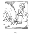
- Fig. 1 is a plan view of a presently preferred embodiment of this invention showing the improved armstack structure on a rotary actuator type of disk memory drive.
- Fig. 2 is a plan view of another preferred embodiment of this invention showing the improved armstack structure in a linear actuator type of disk memory drive; and
- Figs. 3 and 4 are respectively enlarged fragmentary plan and side views of the armstack structure, showing the side-by-side relationship of the individual arms and heads of the improved armstack structure.
- Referring to the plan view of this invention illustrated in Fig. 1, which is the presently preferred embodiment of this invention, there is illustrated a disk memory drive of the rotary actuator type comprising a
magnetic disk assembly 1 adapted to be driven by a motor (not shown). A plurality ofdisks 1a are typically mounted in uniformly axially spaced positions along a spindle which is journalled to rotate about acentral axis 1b. - The actuator 3, which is of the rotary actuator type, is journalled to rotate about an axis 3a. The angular position of the actuator between
limit stops 2 is controlled by an electromagnetic drive generally designated 7 which comprises a permanent magnet structure having anarcuate center pole 7a, the magnetic field of which links acoil 7b carried by the rotary actuator 3 and which surrounds thecenter pole 7a. Thecenter pole 7a is arcuate, as seen, having its arc center at the axis 3a. A servo system including a programmable microprocessor (not shown) provides controlled power for thecoil 7b to move the actuator between selected angular positions, for track seeking and track following purposes as commanded by the microprocessor. As seen, the actuator 3 is mounted in a position beside the magnetic disk stack so that its free end swings toward and away from the disk stack. - A lateral projection or
arm 3b on the free end of the rotary actuator 3 projects towards the disks. Thislateral arm 3b forms part of acomb structure 5a which mounts thearmstack 5. Thecomb structure 5a comprises individual flexure mounting plates 9, Figs. 1, 3 and 4, in which Figs. 3 and 4 are drawn to an enlarged scale with respect to Fig. 1. Note is made here, that Figs. 3 and 4 are plan and side views of thearmstack 5 of the linear actuator disk drive of Fig. 2; however, they differ only in slight design detail from Fig. 1 and reference thereto in this description of the rotary actuator armstack does not involve such detail. These individual flexure mounting plates 9 comprise the teeth of thecomb structure 5a. These flexure mounting plates 9 havebase portions 9a which are individually fitted into uniformly spacedslots 3c, Fig. 1 and Fig. 4, in thelateral arm 3b of the actuator 3. One ormore screws 10 in each flexure mounting plate 9 secures the flexure mounting plate to thelateral arm 3b. The spacing of theslots 3c is such that a line through the center of a flexure mounting plate 9, as viewed edgewise, see Fig. 4, is centered between thedisks 1a. Aprojecting plate section 9c on each flexure mounting plate 9, having upper andlower faces flexures 5b. As seen in Fig. 4, oneflexure 5b is mounted on theface 9e on the bottom side of theplate section 9c, and the other of the twoflexures 5b, seen in Fig. 4, is mounted on the top side of theplate section 9c on thesurface 9d. They are in side-by-side relationship, as viewed in Figs. 3 and 1. The flexure on theupper face 9d is bent downwardly and the flexure on thelower face 9e is bent upwardly. As seen in the side view, Fig. 4, they cross at about their mid-length positions. -
Magnetic heads 5c are mounted on the ends of theflexures 5b by means offlat springs 5d of light weight construction. As seen in plan view, Figs. 1 and 3, they are circumferentially spaced with respect to the disk in side-by-side positions in the armstack. It will be observed from Figs. 1, 3 and 4, that themagnetic head 5c on the downwardlybent flexure 5b faces downwardly and themagnetic head 5c on the upwardlybent flexure 5b faces upwardly. In these positions, the active faces of the magnetic heads are gently biased against the confronting surfaces of the adjacent disks between which they are fitted. Theflexures 5b are shallow channels. The channel sections extend over the tapered portions of the flexures but do not extend into the area where the flexures are mounted, thus providing flexibility of the flexures adjacent the mounting pad or surfaces 9d and 9e. Ahead plate 5e and a center hole attachment such as a rivet or screw 5f, secures each flexure to its mountingsurface plate section 9c. - This staggered structure of heads and flexures eliminates the possibility of collision between the adjacent flexures and their heads, and the collision of the free end of a flexure with a disk, due either to shock forces experienced in normal handling or in typical inflight forces acting on the heads and flexures during disk drive operation.
- The magnetic heads are also relatively longitudinally displaced of the armstack, as seen in Fig. 1. Unlike the linear actuator disk drive of Fig. 2, the rotary actuator disk drive of Fig. 1 does not move the heads over a radial line, but rather along a shallow arc defining two points on a radial line where the arc intercepts the outer and inner tracks. With the rotary actuator, there is only one track where the heads can be aligned or centered on a single track. For the head position shown, the outer track is the selected track on the respective disks. Corrections for head/track positions when selecting one or the other of the heads for recording or reading are progressive from this outer track inwardly on each disk and are easily programmed in a microprocessor forming part of the disk drive servo system. The circumferential displacement of the heads in their side-by-side positions, as shown in plan view, poses no problems with respect to the servo system, since an index mark is provided in each track which together with a sector mark identification in each servo gap of a track, provides timing with respect to the recording or reading of data. A track number provided in each servo gap in each track facilitates track seeking.
- As seen in Fig. 1, angular movement of the actuator 3 is limited between the fixed stops 2 which are secured in the permanent magnet structure 7. Between these extremes of positions, track seeking and track following operations of the disk drive take place.
- The application of this invention to a linear actuator type of disk drive is seen in Figs. 2, 3 and 4. In these figures, parts having a function corresponding to parts of Fig. 1 bear like reference characters.
- The linear electromagnetic driver 7 comprises a pair of
linear center poles 7a which are equally spaced on opposite sides of the central axis of movement of the actuator. A pair ofcoils 7b are provided on the linearly movable actuator, each of which surrounds one of thecenter poles 7a. Thearmstack structure 5 is mounted on thecomb structure 5a on the end of the actuator 3 facing thedisk stack 1. Theflexures 5b are disposed in circumferentially spaced positions with respect to the disk in side-by-side relationship in plan view, with their base ends secured to the individual flexure mounting members 9 of thecomb structure 5a. Themagnetic heads 5c are mounted in circumferentially spaced positions with respect to the disks, on the ends of theflexures 5b. This mounting is the same as that described in connection with Fig. 1. - Figs. 3 and 4 show enlarged plan and side views of the
armstack 5 of Fig. 2. The side view of Fig. 4 illustrates only two sections of the armstack structure, typically comprising seven such sections for a disk stack of eight disks. The arms for the top surface of the top disk and for the bottom surface of the bottom disk each comprise only a single flexure and a single head. They are not shown, being of no interest to this invention. The flexures and magnetic heads of these two sections which are illustrated are positioned between three of thedisks 1a. In Fig. 3, as in Figs. 1 and 2, the uppermost disk has been removed so that a plan view of the armstack structure may be better illustrated. - The central axis of the linear actuator lies in a position between the
heads 5c which corresponds to a radius of the disk. Thus, there is no need for offset between the heads along the armstack axis, and the longitudinal axes of the heads, as viewed in plan, may be aligned in positions normal to the central axis of the actuator to simultaneously center on corresponding tracks in the surfaces of adjacent disks. In the alternative, the heads may be skewed slightly with respect to each other so that each longitudinal axis is tangent to a track arc of its adjacent disk surface at that head location. The thickness of theplate section 9c of the flexure mounting plate 9 together with the thickness of each of thehead plates 5e, is easily controlled, while maintaining structural integrity, so that there is no interference between the surfaces of headplate 5e and mounting rivets orscrews 5f, securing the flexure bases to theextension 9c, and the adjacent surface of one of the disks. - Although specific structural details have been disclosed herein, it will be appreciated that the armstack may be fabricated as an assembled unit with the
lateral arm 3b, if the lateral arm is detachable from the actuator. By this expedient, thearmstack 5 may be assembled or serviced separately from the actuator 3. Theflexures 5b may be inverted from the positions shown on their mounting faces 9d and 9e without relocating the heads on the flexure extremities. This inverts the heads from their present positions to engage opposite disk surfaces. The flexure mountingplate section 9c may be a single piece or two piece construction with the mounting faces 9d and 9e lying in the same plane. These and other structural variations may be practiced using the staggered head construction disclosed.
Claims (10)
Applications Claiming Priority (2)
| Application Number | Priority Date | Filing Date | Title |
|---|---|---|---|
| US07/260,846 US4937693A (en) | 1988-10-20 | 1988-10-20 | Staggered heads for minimizing disk spacing in a disk drive |
| US260846 | 1994-06-16 |
Publications (2)
| Publication Number | Publication Date |
|---|---|
| EP0365150A2 true EP0365150A2 (en) | 1990-04-25 |
| EP0365150A3 EP0365150A3 (en) | 1991-07-03 |
Family
ID=22990866
Family Applications (1)
| Application Number | Title | Priority Date | Filing Date |
|---|---|---|---|
| EP19890309690 Withdrawn EP0365150A3 (en) | 1988-10-20 | 1989-09-22 | Staggered heads for minimizing disk spacing in a disk drive |
Country Status (4)
| Country | Link |
|---|---|
| US (1) | US4937693A (en) |
| EP (1) | EP0365150A3 (en) |
| JP (1) | JPH02156487A (en) |
| KR (1) | KR900006958A (en) |
Cited By (3)
| Publication number | Priority date | Publication date | Assignee | Title |
|---|---|---|---|---|
| DE3940909A1 (en) * | 1988-12-09 | 1990-06-13 | Hitachi Ltd | MAGNETIC DISK UNIT |
| EP0408298A2 (en) * | 1989-07-10 | 1991-01-16 | Compaq Computer Corporation | Head gimbal flexure assembly |
| EP0568965A2 (en) * | 1992-05-04 | 1993-11-10 | Read-Rite Corporation | Assembly of headstacks in disk drives |
Families Citing this family (18)
| Publication number | Priority date | Publication date | Assignee | Title |
|---|---|---|---|---|
| US5189577A (en) * | 1988-12-09 | 1993-02-23 | Hitachi, Ltd. | A magnetic disk apparatus and a motor securement therefor |
| US6600631B1 (en) | 1989-11-27 | 2003-07-29 | Censtor Corp. | Transducer/flexure/conductor structure for electromagnetic read/write system |
| JPH03259480A (en) * | 1990-03-07 | 1991-11-19 | Nec Corp | Magnetic head and magnetic disk device using the head |
| JP2935129B2 (en) * | 1990-05-28 | 1999-08-16 | インターナショナル・ビジネス・マシーンズ・コーポレーション | Fixed magnetic disk drive and related apparatus and method |
| MY124223A (en) * | 1991-09-12 | 2006-06-30 | Hitachi Global Storage Tech Netherlands B V | Disk drive apparatus. |
| JP2565608B2 (en) * | 1991-12-17 | 1996-12-18 | 富士通株式会社 | Disk drive actuator |
| US5343345A (en) * | 1992-05-01 | 1994-08-30 | Gilovich Paul A | Magnetic disk storage apparatus with multiple sets of actuator arms for read/write operations at different circumferential locations within the disk stack |
| US5381289A (en) * | 1993-02-26 | 1995-01-10 | Hutchinson Technology Incorporated | Suspension for in-line offset head mounting |
| JPH0798949A (en) * | 1993-09-16 | 1995-04-11 | Internatl Business Mach Corp <Ibm> | Suspension system |
| US6313970B1 (en) * | 1994-02-18 | 2001-11-06 | Maxtor Corporation | Disk drive with low profile suspension assemblies |
| JPH0896540A (en) * | 1994-09-28 | 1996-04-12 | Fujitsu Ltd | Magnetic disk device and head assembly |
| KR100199191B1 (en) | 1995-05-10 | 1999-06-15 | 윤종용 | Disc drive recording apparatus and head switching controlling method with double head gimbal assembly |
| JP3400248B2 (en) * | 1995-08-30 | 2003-04-28 | インターナショナル・ビジネス・マシーンズ・コーポレーション | Head suspension load beam for disk drive devices |
| US5710680A (en) * | 1995-12-22 | 1998-01-20 | Pc Peripherals Inc. | Magnetic hard disk drive head suspension apparatus |
| US7092184B2 (en) | 2002-08-05 | 2006-08-15 | Seagate Technology Llc | Monitoring a sensor's output using a target window that is based on a longitudinal offset's position-dependent indicator |
| US9911442B1 (en) | 2016-11-23 | 2018-03-06 | Seagate Technology Llc | Feedforward compensation for multi-actuator hard drives |
| US10446180B1 (en) | 2018-03-21 | 2019-10-15 | Seagate Technology Llc | Multi-actuator interconnector |
| US10803893B1 (en) | 2019-06-03 | 2020-10-13 | Seagate Technology Llc | Data transfer scheduling for fairness and balance |
Citations (6)
| Publication number | Priority date | Publication date | Assignee | Title |
|---|---|---|---|---|
| JPS59119581A (en) * | 1982-12-27 | 1984-07-10 | Hitachi Ltd | Magnetic disk device |
| JPS6029988A (en) * | 1983-07-29 | 1985-02-15 | Mitsubishi Electric Corp | Magnetic disk device |
| JPS619818A (en) * | 1984-06-25 | 1986-01-17 | Toshiba Corp | Magnetic disk device |
| JPS6284419A (en) * | 1985-10-09 | 1987-04-17 | Seiko Epson Corp | Magnetic head supporting device |
| US4800455A (en) * | 1985-05-07 | 1989-01-24 | Kabushiki Kaisha Toshiba | Magnetic disk drive having a magnetic-head with a head gap supported parallel to the moving direction of a magnetic-head positioning mechanism |
| US4835641A (en) * | 1986-05-19 | 1989-05-30 | Mitsubishi Denki Kabushiki Kaisha | Magnetic disk apparatus |
Family Cites Families (1)
| Publication number | Priority date | Publication date | Assignee | Title |
|---|---|---|---|---|
| US4843503A (en) * | 1987-12-17 | 1989-06-27 | Priam Corporation | Head arm damping device for disc drive actuators |
-
1988
- 1988-10-20 US US07/260,846 patent/US4937693A/en not_active Expired - Fee Related
-
1989
- 1989-09-22 EP EP19890309690 patent/EP0365150A3/en not_active Withdrawn
- 1989-10-19 KR KR1019890015115A patent/KR900006958A/en not_active Application Discontinuation
- 1989-10-20 JP JP1273616A patent/JPH02156487A/en active Pending
Patent Citations (6)
| Publication number | Priority date | Publication date | Assignee | Title |
|---|---|---|---|---|
| JPS59119581A (en) * | 1982-12-27 | 1984-07-10 | Hitachi Ltd | Magnetic disk device |
| JPS6029988A (en) * | 1983-07-29 | 1985-02-15 | Mitsubishi Electric Corp | Magnetic disk device |
| JPS619818A (en) * | 1984-06-25 | 1986-01-17 | Toshiba Corp | Magnetic disk device |
| US4800455A (en) * | 1985-05-07 | 1989-01-24 | Kabushiki Kaisha Toshiba | Magnetic disk drive having a magnetic-head with a head gap supported parallel to the moving direction of a magnetic-head positioning mechanism |
| JPS6284419A (en) * | 1985-10-09 | 1987-04-17 | Seiko Epson Corp | Magnetic head supporting device |
| US4835641A (en) * | 1986-05-19 | 1989-05-30 | Mitsubishi Denki Kabushiki Kaisha | Magnetic disk apparatus |
Non-Patent Citations (4)
| Title |
|---|
| PATENT ABSTRACTS OF JAPAN vol. 10, no. 157 (P-464)(2213) 6 June 1986, & JP-A-61 009818 (TOSHIBA K.K.) 17 January 1986, * |
| PATENT ABSTRACTS OF JAPAN vol. 11, no. 287 (P-617)(2734) 17 September 1987, & JP-A-62 084419 (SEIKO EPSON CORP) 17 April 1987, * |
| PATENT ABSTRACTS OF JAPAN vol. 8, no. 248 (P-313)(1685) 14 November 1984, & JP-A-59 119581 (HITACHI SEISAKUSHO K.K.) 10 July 1984, * |
| PATENT ABSTRACTS OF JAPAN vol. 9, no. 156 (P-368)(1879) 29 June 1985, & JP-A-60 029988 (MITSUBISHI DENKI K.K.) 15 February 1985, * |
Cited By (6)
| Publication number | Priority date | Publication date | Assignee | Title |
|---|---|---|---|---|
| DE3940909A1 (en) * | 1988-12-09 | 1990-06-13 | Hitachi Ltd | MAGNETIC DISK UNIT |
| DE3940909C2 (en) * | 1988-12-09 | 2002-04-25 | Hitachi Ltd | Magnetic disk unit |
| EP0408298A2 (en) * | 1989-07-10 | 1991-01-16 | Compaq Computer Corporation | Head gimbal flexure assembly |
| EP0408298A3 (en) * | 1989-07-10 | 1991-07-03 | Compaq Computer Corporation | Head gimbal flexure assembly |
| EP0568965A2 (en) * | 1992-05-04 | 1993-11-10 | Read-Rite Corporation | Assembly of headstacks in disk drives |
| EP0568965A3 (en) * | 1992-05-04 | 1994-09-28 | Read Rite Corp | Assembly of headstacks in disk drives |
Also Published As
| Publication number | Publication date |
|---|---|
| KR900006958A (en) | 1990-05-09 |
| EP0365150A3 (en) | 1991-07-03 |
| JPH02156487A (en) | 1990-06-15 |
| US4937693A (en) | 1990-06-26 |
Similar Documents
| Publication | Publication Date | Title |
|---|---|---|
| US4937693A (en) | Staggered heads for minimizing disk spacing in a disk drive | |
| US4939611A (en) | Vertical displacement limit stop in a disk drive for preventing disk surface damage | |
| US6032352A (en) | Method of manufacturing rigid disk drive with dynamic head loading apparatus | |
| US6160684A (en) | Head suspension having tabs and force isolation welds for gram load reduction during swaging | |
| DE3107225C2 (en) | ||
| US7477489B1 (en) | Actuator including an actuator arm with a first microactuator supporting a read head and a force-balancing microactuator without any read head | |
| EP0582284A1 (en) | Magnetic head suspension assembly | |
| US5239431A (en) | Head lift limiter for a disk drive | |
| US4422115A (en) | Lightweight dual head support assembly for magnetic disk drives | |
| US5268805A (en) | Low inertia Winchester disk drive actuator | |
| US6452755B2 (en) | Microactuator suspension with multiple “I” shaped microbeams | |
| US3544980A (en) | Magnetic recording disc drive with head positioning and collision avoidance apparatus | |
| US6765759B2 (en) | Resonance four piece suspension | |
| US4992898A (en) | Magnetic head slider suspension assembly having inverted load rails | |
| US4740854A (en) | Flexure seat for a transducer head of a magnetic disk apparatus | |
| KR0131756B1 (en) | Disk drive | |
| US4651243A (en) | Suspension for magnetic transducer | |
| US5081553A (en) | Combination of elongated load arm and microminimonolithic head slider | |
| EP0259952A1 (en) | Head support system for dual head disc drive | |
| US5659448A (en) | Magnetic head supporting mechanism including a slider fixed to a slider spacer by a fixing area smaller than a contact area | |
| JP2678401B2 (en) | Inline type head suspension | |
| US4868696A (en) | Linear actuator using a compound parallel bendable element suspension system | |
| EP0564763A1 (en) | Disk drive having an improved transducer suspension assembly | |
| USH1425H (en) | Head suspension assembly having improved frequency response, accurate head positioning and minimized flying variation | |
| US6304420B1 (en) | Preloaded gimbal in a head suspension for limiting head/disc separation |
Legal Events
| Date | Code | Title | Description |
|---|---|---|---|
| PUAI | Public reference made under article 153(3) epc to a published international application that has entered the european phase |
Free format text: ORIGINAL CODE: 0009012 |
|
| AK | Designated contracting states |
Kind code of ref document: A2 Designated state(s): DE FR GB |
|
| PUAL | Search report despatched |
Free format text: ORIGINAL CODE: 0009013 |
|
| AK | Designated contracting states |
Kind code of ref document: A3 Designated state(s): DE FR GB |
|
| 17P | Request for examination filed |
Effective date: 19910913 |
|
| 17Q | First examination report despatched |
Effective date: 19930318 |
|
| STAA | Information on the status of an ep patent application or granted ep patent |
Free format text: STATUS: THE APPLICATION IS DEEMED TO BE WITHDRAWN |
|
| 18D | Application deemed to be withdrawn |
Effective date: 19930729 |