EP0364418A2 - Moteur à fonctionnement linéaire - Google Patents
Moteur à fonctionnement linéaire Download PDFInfo
- Publication number
- EP0364418A2 EP0364418A2 EP89850302A EP89850302A EP0364418A2 EP 0364418 A2 EP0364418 A2 EP 0364418A2 EP 89850302 A EP89850302 A EP 89850302A EP 89850302 A EP89850302 A EP 89850302A EP 0364418 A2 EP0364418 A2 EP 0364418A2
- Authority
- EP
- European Patent Office
- Prior art keywords
- driven member
- locking means
- length
- motor
- shaft
- Prior art date
- Legal status (The legal status is an assumption and is not a legal conclusion. Google has not performed a legal analysis and makes no representation as to the accuracy of the status listed.)
- Withdrawn
Links
- 239000012528 membrane Substances 0.000 description 5
- 238000006073 displacement reaction Methods 0.000 description 2
- 230000000694 effects Effects 0.000 description 2
- 230000006870 function Effects 0.000 description 2
- 238000010248 power generation Methods 0.000 description 2
- 238000006243 chemical reaction Methods 0.000 description 1
- 239000000463 material Substances 0.000 description 1
- 230000007246 mechanism Effects 0.000 description 1
- 239000002184 metal Substances 0.000 description 1
- 230000004048 modification Effects 0.000 description 1
- 238000012986 modification Methods 0.000 description 1
Images


Classifications
-
- H—ELECTRICITY
- H02—GENERATION; CONVERSION OR DISTRIBUTION OF ELECTRIC POWER
- H02N—ELECTRIC MACHINES NOT OTHERWISE PROVIDED FOR
- H02N2/00—Electric machines in general using piezoelectric effect, electrostriction or magnetostriction
- H02N2/02—Electric machines in general using piezoelectric effect, electrostriction or magnetostriction producing linear motion, e.g. actuators; Linear positioners ; Linear motors
- H02N2/021—Electric machines in general using piezoelectric effect, electrostriction or magnetostriction producing linear motion, e.g. actuators; Linear positioners ; Linear motors using intermittent driving, e.g. step motors, piezoleg motors
- H02N2/023—Inchworm motors
Definitions
- the present invention refers to a linearily operating motor for stepwise advance of a driven member, such as a shaft, incorporating an elongated body with length variable properties and means for altering the length of said body.
- a motor of the above mentioned type is described in Swedish patent application no. 8700219-2.
- the elongated body has magnetostrictive properties, whereby the motion required for advance the driven member is brought about by axial displacement of the body.
- the purpose of the present invention is to provide a motor of the type mentioned in the introduction, wherein the elongated body is stationary and the motion required for effecting the advance of the driven member is obtained by means of the elongation of the body.
- a motor according to the invention is intended to be used e.g. where high precision is required for the motion generated, such as at traversing motors for precision adjustment and where the requirements for stroke length and power generation are rather small but also at applications, where longer stroke and bigger power generation are required, such as in manoeuvre of hoisting mechanisms.
- Lineary operating motors relate to passive forms of actuator applications, i.e. the length increase of the elongated body is transferred to the driven member via a gripping device in such a manner that said member is subjected to a step-wise advance.
- a motor working in accordance with the step-advance principle is generally illustrated in Fig. 1, whereby one or more, in the figure two, elongated bodies 10 having length variable properties are arranged to advance a shaft 11 step-wise.
- Two locking members 12, 13 are arranged to be brought in engage- ment with the shaft 11. The locking member 12 thereby seizes the shaft 11, whereupon the feeding units 10 advance the shaft. The locking member 13 then seizes the shaft 11, whereupon the locking member 12 releases its grip about the shaft and the feeding units 10 resume their initial length.
- Fig. 1 Even if the general application of the invention in Fig. 1 is illustrated in connection to two locking members it is however possible, as will be described later in this description, to effect the desired advance of the shaft 11 by means of one locking member only.
- An essential feature of the invention thereby is that the locking member 12 and the elongated body 10 are designed mutually in such a manner that the locking member due to the length increase of the body is brought to engagement with the driven member 11.
- the locking member 12 then is designed with a freewheel function thus that the grip of the locking member about the member 11 terminates when the body 10 resumes its initial length.
- the invention is intended to be applied primarily on applications where the feeding units 10 are bodies having such magnetostrictive properties that the bodies will undergo a length increase under influence of a magnetic field.
- Such magnetostrictive materials and the influence given to them by magnetic fields are described in detail in Swedish patent application No. 8700219-2, and therefore the contents of that patent application is incorporated in the present description.
- the invention however is generally applicable in combination with other stationary elongated bodies with length variable properties.
- bodies can be mentioned a rod or a bundle of threads of memory metal, which undergo a length change at a certain temperature.
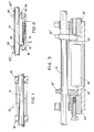
- the locking members 12′, 13′ are pivotably supported about pivot axles 14 and designed with through-holes for the shaft 11.
- the length increase of the rod is transferred to a guide 16, in which the axel 14 is supported.
- the locking member 12′ in the initial stage of the length increase will be tilted, whereby a firm grip will be obtained between the shaft 11 and the edges of the hole in the locking member.
- the locking member 12′ thereupon will be displaced by the rod 10 in the direction of the shaft 11 and it thereby will pull along the shaft 11.
- the locking member 12′ thereupon first moves back to its direction mainly perpendicular to the shaft 11 as shown in Fig. 2, whereupon the locking member 12′ is moved backwards realtive to the shaft 11, as seen in the advance direction thereof.
- the rod 11 If no or only small axial loads act upon the rod 11 in a direction opposed to the advance direction thereof, it is possible to advance the rod 11 by means of a single locking member 12′. If essential axial loads are present, it is possible to provide a second locking member 13′ at the opposite end of the rod 11.
- the locking member 13′ is arranged not to be displaced axially at advance of the rod 11 but only to change its pivot position relative to the shaft 11 depending on if the locking member 13′ shall lock or not.
- the locking members 12′, 13′ thus operate alterantively in such a manner that the locking member 13′ is disengaged due to movement of the shaft when the locking member 12′ is engaged and moves the shaft 11. When the locking member 12′ thereupon is returned to take a new grip the locking member 13′ will lock.
- the locking members 12′, 13′ are spring loaded in axial direction by means of springs 17, 18 and radially from below by means of not shown springs for improving the locking effect.
- a part of the magnetic field generated in the coil 15 is arranged to be "recovered” by means of a magnetic return cable 19, which contacts both short ends of the rod 10.
- the movement of the rod 10 is transferred via the return cable 19 to the guides 16 at the two short ends of the rod.
- the function of the guides 16 is, beside transferring the power to the locking members 12′, 13′ via the axles 14′, to guide the movement of the axles 14′ thus that this will occur in the longitudinal direction of the shaft 11.
- the motor housing 20 is designed in such a manner that the shaft 11 can be fed in both directions.
- this pretension is generated by means of a spring 21 acting upon the rearmost, i.e. the right hand guide 16 in Fig. 2.
- Fig. 3 is shown a modification of the step-wise advanced annular oscillator in Fig. 2, wherein the rod 10 acts directly upon the locking member or upon the freewheel 12 ⁇ .
- the pretension of the rod 10 and the returning of the locking member 12 ⁇ after terminated step-wise advance of the shaft 11 are effected by means of a spring 22.
- the reaction force from the spring 22 is transferred via the rod 10 and the rearmost freewheel 13 ⁇ to a counter-stay 23 in the housing 20.
- the rod 10 rests against the freewheel 13 ⁇ .
- this embodiment may be modified in such a manner that the rod 10 is adapted to rest on a fixed surface in the housing 20.
- the rod 10 and the freewheel 12 ⁇ thereby are the only movable parts.
- a tension spring the other end of which is attached to the housing 20.
- the shaft 11 is advanced by means of a locking member 12′′′ in form of a gear unit 24, 25.
- a lever 24 connected thereto and forming part of the gear unit is arranged to pivot in a direction towards the shaft 11.
- the lever 24 is connected to a friction element 25 in such a manner that the friction element 25 advances the shaft 11 at pivoting of the lever 24.
- the lever ratio and the angle of the friction element 25 are such that a step-up of the extension of the rod 10 in the order of 10 times is obtained.
- the locking members 12 IV , 13 IV incorporate gripping membranes 26, 27, 28, 29.
- the gripping membrane 26 At extension of the rods 10 the gripping membrane 26 in engagement with the shaft 11 advances this, whereby the gripping membrane 28 allows the shaft 11 to pass.
- the gripping membrane 26 At return movement of the rods 10 the gripping membrane 26 is released from the shaft 11, whereby the gripping membrane holds the shaft load.
- the locking members 12 V , 13 V incorporate an annular member 30 and a wedge member 31.
- the annular member 30 is pressed against the wedge member 31 by means of a spring 32.
- the right hand wedge member 31 as seen in Fig. 6 is pressed against the annular member 30, which is pressed against the shaft 11 and thereby grips this and displaces the shaft.
- the shaft 11 is prevented from moving in its advance direction by means of the locking member 12 V .
Applications Claiming Priority (2)
| Application Number | Priority Date | Filing Date | Title |
|---|---|---|---|
| SE8803659A SE462311B (sv) | 1988-10-13 | 1988-10-13 | Linjaert arbetande motor |
| SE8803659 | 1988-10-13 |
Publications (2)
| Publication Number | Publication Date |
|---|---|
| EP0364418A2 true EP0364418A2 (fr) | 1990-04-18 |
| EP0364418A3 EP0364418A3 (fr) | 1991-01-02 |
Family
ID=20373625
Family Applications (1)
| Application Number | Title | Priority Date | Filing Date |
|---|---|---|---|
| EP19890850302 Withdrawn EP0364418A3 (fr) | 1988-10-13 | 1989-09-14 | Moteur à fonctionnement linéaire |
Country Status (4)
| Country | Link |
|---|---|
| US (1) | US5013945A (fr) |
| EP (1) | EP0364418A3 (fr) |
| JP (1) | JPH02152808A (fr) |
| SE (1) | SE462311B (fr) |
Cited By (4)
| Publication number | Priority date | Publication date | Assignee | Title |
|---|---|---|---|---|
| WO1995000976A1 (fr) * | 1993-06-22 | 1995-01-05 | Qenico Ab | Agencement generateur de force et/ou de mouvement |
| DE4329163A1 (de) * | 1993-08-30 | 1995-03-02 | Stm Medtech Starnberg | Piezoelektrische Antriebseinheit |
| DE10248426A1 (de) * | 2002-10-17 | 2004-05-06 | Deutsches Zentrum für Luft- und Raumfahrt e.V. | Linearschrittmotor |
| FR2854284A1 (fr) * | 2003-04-28 | 2004-10-29 | Centre Nat Rech Scient | Moteur piezoelectrique permettant au moins deux degres de liberte, en rotation et en deplacement lineaire |
Families Citing this family (7)
| Publication number | Priority date | Publication date | Assignee | Title |
|---|---|---|---|---|
| US5148067A (en) * | 1991-07-01 | 1992-09-15 | Lasota Laurence | Latching linear motor |
| US5271259A (en) * | 1992-06-12 | 1993-12-21 | Ball Corporation | Electromagnetic redraw actuator |
| US5389845A (en) * | 1993-11-22 | 1995-02-14 | Technical Research Associates, Inc. | Linear actuator apparatus and method |
| US6300692B1 (en) | 2000-03-29 | 2001-10-09 | Ford Global Technologies, Inc. | Linear actuator with expansion device |
| US6936951B1 (en) | 2000-11-27 | 2005-08-30 | Grq Instruments, Inc. | Smart sonic bearings and method for frictional force reduction and switching |
| CA2522192A1 (fr) * | 2003-04-14 | 2004-10-21 | The Buehrmann Trust | Appareil permettant d'imprimer un deplacement relatif entre un organe oscillant et un rail |
| US7227440B2 (en) * | 2005-03-03 | 2007-06-05 | Pratt & Whitney Canada Corp. | Electromagnetic actuator |
Citations (2)
| Publication number | Priority date | Publication date | Assignee | Title |
|---|---|---|---|---|
| US3902084A (en) * | 1974-05-30 | 1975-08-26 | Burleigh Instr | Piezoelectric electromechanical translation apparatus |
| JPS6285682A (ja) * | 1985-10-07 | 1987-04-20 | Nec Corp | 圧電駆動機構 |
Family Cites Families (6)
| Publication number | Priority date | Publication date | Assignee | Title |
|---|---|---|---|---|
| US2506141A (en) * | 1947-08-14 | 1950-05-02 | Drouin Pierre Andre | Uniform microdisplacement device, particularly for gratings scriber |
| FR1005585A (fr) * | 1947-08-14 | 1952-04-11 | Dispositif pour l'obtention automatique de petits déplacements, aotamment en vue dela fabrication de réseau de diffraction | |
| US3138749A (en) * | 1962-03-05 | 1964-06-23 | George R Stibitz | Incremental feed mechanisms |
| US3217218A (en) * | 1962-07-23 | 1965-11-09 | Floyd G Steele | Alternating energy control system |
| US3349304A (en) * | 1965-04-05 | 1967-10-24 | William J Wachter | Longitudinal movement mechanism |
| NL7302941A (fr) * | 1973-03-02 | 1974-09-04 |
-
1988
- 1988-10-13 SE SE8803659A patent/SE462311B/sv not_active IP Right Cessation
-
1989
- 1989-09-14 EP EP19890850302 patent/EP0364418A3/fr not_active Withdrawn
- 1989-10-02 US US07/416,390 patent/US5013945A/en not_active Expired - Fee Related
- 1989-10-12 JP JP1264088A patent/JPH02152808A/ja active Pending
Patent Citations (2)
| Publication number | Priority date | Publication date | Assignee | Title |
|---|---|---|---|---|
| US3902084A (en) * | 1974-05-30 | 1975-08-26 | Burleigh Instr | Piezoelectric electromechanical translation apparatus |
| JPS6285682A (ja) * | 1985-10-07 | 1987-04-20 | Nec Corp | 圧電駆動機構 |
Non-Patent Citations (1)
| Title |
|---|
| PATENT ABSTRACTS OF JAPAN vol. 11, no. 286 (E-541)(2733) 16 September 1987, & JP-A-62 085682 (NEC CORPORATION) 20 April 1987, * |
Cited By (8)
| Publication number | Priority date | Publication date | Assignee | Title |
|---|---|---|---|---|
| WO1995000976A1 (fr) * | 1993-06-22 | 1995-01-05 | Qenico Ab | Agencement generateur de force et/ou de mouvement |
| US5694097A (en) * | 1993-06-22 | 1997-12-02 | Oenico Ab | Force and/or motion generating arrangement |
| DE4329163A1 (de) * | 1993-08-30 | 1995-03-02 | Stm Medtech Starnberg | Piezoelektrische Antriebseinheit |
| DE10248426A1 (de) * | 2002-10-17 | 2004-05-06 | Deutsches Zentrum für Luft- und Raumfahrt e.V. | Linearschrittmotor |
| FR2854284A1 (fr) * | 2003-04-28 | 2004-10-29 | Centre Nat Rech Scient | Moteur piezoelectrique permettant au moins deux degres de liberte, en rotation et en deplacement lineaire |
| WO2004098039A2 (fr) * | 2003-04-28 | 2004-11-11 | Centre National De La Recherche Scientifique | Moteur piezoelectrique permettant au moins deux degres de liberte, en rotation et en deplacement lineaire |
| WO2004098039A3 (fr) * | 2003-04-28 | 2004-12-23 | Centre Nat Rech Scient | Moteur piezoelectrique permettant au moins deux degres de liberte, en rotation et en deplacement lineaire |
| US7671513B2 (en) | 2003-04-28 | 2010-03-02 | Centre National De La Recherche Scientifique | Piezoelectric motor allowing at least two degrees of freedom, in rotation and linear displacement |
Also Published As
| Publication number | Publication date |
|---|---|
| SE8803659L (sv) | 1990-04-14 |
| SE462311B (sv) | 1990-05-28 |
| JPH02152808A (ja) | 1990-06-12 |
| US5013945A (en) | 1991-05-07 |
| SE8803659D0 (sv) | 1988-10-13 |
| EP0364418A3 (fr) | 1991-01-02 |
Similar Documents
| Publication | Publication Date | Title |
|---|---|---|
| EP0364418A2 (fr) | Moteur à fonctionnement linéaire | |
| DE19703230B4 (de) | Magnetostriktive Bremse | |
| EP1421293B2 (fr) | Dispositif de serrage d'un frein | |
| US5988006A (en) | Method of moving objects with self-locking mechanical transmission | |
| US5092432A (en) | Mechanical energy storage for vehicle parking brakes | |
| US5389845A (en) | Linear actuator apparatus and method | |
| DE102012221891B3 (de) | Antriebsvorrichtung und -verfahren zur linearen und/oder rotatorischen Positionierung | |
| LU93045B1 (de) | Motorisiertes Gelenk für einen programmierbaren Bewegungsautomaten | |
| WO2017186847A1 (fr) | Articulation motorisée pour un automate de déplacement programmable | |
| EP1354147B1 (fr) | Frein de stationnement electromoteur, notamment pour un vehicule automobile | |
| US5231887A (en) | Device in a force actuator | |
| EP1319859B1 (fr) | Dispositif de freinage | |
| US20020180310A1 (en) | Linear piezoelectric motor with self locking means | |
| US5097161A (en) | Linear actuator | |
| US20140333180A1 (en) | Piezoelectric actuation device | |
| EP3301730B1 (fr) | Convertisseur d'énergie | |
| DE60201438T2 (de) | Linearer aktuator, insbesondere aktuator für flugzeugbremsen | |
| JPS5582830A (en) | Blake actuator | |
| DE102021118865A1 (de) | Motorvorrichtung | |
| EP2356705A2 (fr) | Entraînement universel électrique de piézomoteur | |
| EP2804197B1 (fr) | Mécanisme de verrouillage pour l'activation d'un commutateur | |
| SU1652163A1 (ru) | Механизм совмещенного управлени фрикционами и тормозами | |
| GB2037468A (en) | Drive for railway points | |
| JPH11351349A (ja) | アクチュエータ | |
| WO2001033583A1 (fr) | Dispositif de commande d'arbre |
Legal Events
| Date | Code | Title | Description |
|---|---|---|---|
| PUAI | Public reference made under article 153(3) epc to a published international application that has entered the european phase |
Free format text: ORIGINAL CODE: 0009012 |
|
| AK | Designated contracting states |
Kind code of ref document: A2 Designated state(s): DE FR GB IT |
|
| PUAL | Search report despatched |
Free format text: ORIGINAL CODE: 0009013 |
|
| AK | Designated contracting states |
Kind code of ref document: A3 Designated state(s): DE FR GB IT |
|
| 17P | Request for examination filed |
Effective date: 19910612 |
|
| 17Q | First examination report despatched |
Effective date: 19930608 |
|
| STAA | Information on the status of an ep patent application or granted ep patent |
Free format text: STATUS: THE APPLICATION IS DEEMED TO BE WITHDRAWN |
|
| 18D | Application deemed to be withdrawn |
Effective date: 19931019 |