EP0364362B1 - Method and device for logging non-eruptive wells - Google Patents
Method and device for logging non-eruptive wells Download PDFInfo
- Publication number
- EP0364362B1 EP0364362B1 EP89402813A EP89402813A EP0364362B1 EP 0364362 B1 EP0364362 B1 EP 0364362B1 EP 89402813 A EP89402813 A EP 89402813A EP 89402813 A EP89402813 A EP 89402813A EP 0364362 B1 EP0364362 B1 EP 0364362B1
- Authority
- EP
- European Patent Office
- Prior art keywords
- accordance
- measuring means
- flow
- well
- upstream
- Prior art date
- Legal status (The legal status is an assumption and is not a legal conclusion. Google has not performed a legal analysis and makes no representation as to the accuracy of the status listed.)
- Expired - Lifetime
Links
- 238000000034 method Methods 0.000 title claims description 22
- 238000005259 measurement Methods 0.000 claims description 58
- 238000004519 manufacturing process Methods 0.000 claims description 53
- 238000011144 upstream manufacturing Methods 0.000 claims description 37
- 230000004913 activation Effects 0.000 claims description 24
- 230000008569 process Effects 0.000 claims description 8
- 230000001105 regulatory effect Effects 0.000 claims 1
- 239000012530 fluid Substances 0.000 description 28
- 239000004576 sand Substances 0.000 description 16
- XLYOFNOQVPJJNP-UHFFFAOYSA-N water Substances O XLYOFNOQVPJJNP-UHFFFAOYSA-N 0.000 description 15
- 239000000203 mixture Substances 0.000 description 7
- 230000005540 biological transmission Effects 0.000 description 6
- 230000015572 biosynthetic process Effects 0.000 description 5
- 230000008901 benefit Effects 0.000 description 4
- 238000009530 blood pressure measurement Methods 0.000 description 4
- 230000005484 gravity Effects 0.000 description 3
- 238000007789 sealing Methods 0.000 description 3
- 241001508691 Martes zibellina Species 0.000 description 2
- 230000003213 activating effect Effects 0.000 description 2
- 238000009434 installation Methods 0.000 description 2
- 239000007788 liquid Substances 0.000 description 2
- 230000014759 maintenance of location Effects 0.000 description 2
- 239000002245 particle Substances 0.000 description 2
- 230000001012 protector Effects 0.000 description 2
- 238000005086 pumping Methods 0.000 description 2
- 238000011084 recovery Methods 0.000 description 2
- 230000004044 response Effects 0.000 description 2
- 239000007787 solid Substances 0.000 description 2
- 241000287127 Passeridae Species 0.000 description 1
- 238000010521 absorption reaction Methods 0.000 description 1
- 230000000712 assembly Effects 0.000 description 1
- 238000000429 assembly Methods 0.000 description 1
- 238000009529 body temperature measurement Methods 0.000 description 1
- 239000004020 conductor Substances 0.000 description 1
- 238000007596 consolidation process Methods 0.000 description 1
- 238000001739 density measurement Methods 0.000 description 1
- 238000013461 design Methods 0.000 description 1
- 238000001514 detection method Methods 0.000 description 1
- 230000006866 deterioration Effects 0.000 description 1
- 238000011161 development Methods 0.000 description 1
- 238000010586 diagram Methods 0.000 description 1
- 239000006185 dispersion Substances 0.000 description 1
- 238000009826 distribution Methods 0.000 description 1
- 238000005553 drilling Methods 0.000 description 1
- 230000000694 effects Effects 0.000 description 1
- 230000005611 electricity Effects 0.000 description 1
- 230000004941 influx Effects 0.000 description 1
- 238000005304 joining Methods 0.000 description 1
- 239000003129 oil well Substances 0.000 description 1
- 230000035515 penetration Effects 0.000 description 1
- 239000000700 radioactive tracer Substances 0.000 description 1
- 230000009467 reduction Effects 0.000 description 1
- 238000012552 review Methods 0.000 description 1
- 239000000523 sample Substances 0.000 description 1
- 238000005070 sampling Methods 0.000 description 1
- 230000003068 static effect Effects 0.000 description 1
- 239000000126 substance Substances 0.000 description 1
- 238000012360 testing method Methods 0.000 description 1
- 238000012549 training Methods 0.000 description 1
- 238000012546 transfer Methods 0.000 description 1
- 238000010200 validation analysis Methods 0.000 description 1
- 238000012795 verification Methods 0.000 description 1
Images

Classifications
-
- E—FIXED CONSTRUCTIONS
- E21—EARTH DRILLING; MINING
- E21B—EARTH DRILLING, e.g. DEEP DRILLING; OBTAINING OIL, GAS, WATER, SOLUBLE OR MELTABLE MATERIALS OR A SLURRY OF MINERALS FROM WELLS
- E21B49/00—Testing the nature of borehole walls; Formation testing; Methods or apparatus for obtaining samples of soil or well fluids, specially adapted to earth drilling or wells
- E21B49/08—Obtaining fluid samples or testing fluids, in boreholes or wells
- E21B49/087—Well testing, e.g. testing for reservoir productivity or formation parameters
-
- E—FIXED CONSTRUCTIONS
- E21—EARTH DRILLING; MINING
- E21B—EARTH DRILLING, e.g. DEEP DRILLING; OBTAINING OIL, GAS, WATER, SOLUBLE OR MELTABLE MATERIALS OR A SLURRY OF MINERALS FROM WELLS
- E21B43/00—Methods or apparatus for obtaining oil, gas, water, soluble or meltable materials or a slurry of minerals from wells
- E21B43/12—Methods or apparatus for controlling the flow of the obtained fluid to or in wells
- E21B43/121—Lifting well fluids
- E21B43/128—Adaptation of pump systems with down-hole electric drives
-
- E—FIXED CONSTRUCTIONS
- E21—EARTH DRILLING; MINING
- E21B—EARTH DRILLING, e.g. DEEP DRILLING; OBTAINING OIL, GAS, WATER, SOLUBLE OR MELTABLE MATERIALS OR A SLURRY OF MINERALS FROM WELLS
- E21B47/00—Survey of boreholes or wells
- E21B47/06—Measuring temperature or pressure
-
- E—FIXED CONSTRUCTIONS
- E21—EARTH DRILLING; MINING
- E21B—EARTH DRILLING, e.g. DEEP DRILLING; OBTAINING OIL, GAS, WATER, SOLUBLE OR MELTABLE MATERIALS OR A SLURRY OF MINERALS FROM WELLS
- E21B47/00—Survey of boreholes or wells
- E21B47/10—Locating fluid leaks, intrusions or movements
Definitions
- the present invention relates to a method and a device for logging production in inclined or horizontal wells.
- Intervention can on the other hand be made difficult, if not impossible, due to the provisional completion which will have been used during the first phase of exploitation of the well, for example by the use of a non-cemented perforated tube (generally called “pre liner” -perforated “by specialists).
- pre liner a non-cemented perforated tube
- this mode of production (1st non-selective phase, 2nd selective phase) can, in some cases, be the cause of a decrease in ultimate recovery.
- the first solution (selectivity from the start of production) therefore seems more attractive on a technical level, but not necessarily on an economic level.
- Document FR 2 519 689 discloses an installation for testing and activation, but the effluent from upstream or downstream cannot be dissociated from the measurement means. In addition, this method is not suitable for inclined or horizontal wells.
- the case of the perforated tube is that which combines all the difficulties. This is what will be considered later, the cases of production measurements within other completions can be obtained by introducing the corresponding simplifications.
- the present invention relates to the case where the well is non-eruptive and must be activated to produce.
- the present invention can also be applied to vertical wells.
- the essential purpose of a production log is to provide the flow profile of each phase along the drain. This result is obtained by carrying out and interpreting one or more measurements made in the well.
- the main common measures are: - "spinner” type measurement.
- Devices of this type provide the rotational speed of a propeller driven by the flow. The measurement therefore depends essentially on the flow speed of the fluid, but also on its viscosity.
- the problems associated with this type of measurement arise essentially from the heterogeneity of the velocity field in a cross section of the well, from the stratified nature of the flow, from a possible difference in the flow velocities of each phase, from possible counter-current movements, for example with a flow in the opposite direction behind the tube (case of non-cemented completion) or, if a dispersed flow can be obtained, the need to know the composition of the fluid in each phase and the viscosity of the mixture .
- a casing is used, generally designated in English by "tubing" for lowering the measuring tools.
- the well is activated to carry out the measurements.
- the casing can be fitted using a pump enabling the well to be activated.
- the drive mode of the pump will then be either electric or hydraulic (turbopump or jet pump).
- the present invention relates to a method for performing production logs in a non-eruptive well having or not an inclined or horizontal part.
- This process includes the installation of at least one measurement means upstream of an activation means, eg a pump, the activation of the well to cause the production of effluents from both upstream and downstream sides with respect to said measuring means and the treatment by said measuring means of at least part of the effluent coming from the part of the well upstream of said measuring means.
- an activation means eg a pump
- the first measurement means can deal substantially with the entire upstream flow.
- the second measurement means will be able to process substantially all of the downstream flow.
- conservation reports may be carried out, in particular debits from one or more phases.
- the first measurement means can be calibrated by eliminating the downstream flow.
- the present invention also relates to a device for carrying out production logs in a non-eruptive well, this device comprises activation means for activating the production of the well, at least one measuring means, this means being placed upstream of said means. activation, connection means comprising at least one opening between the activation means and said measuring means, the measuring means being adapted to treat at least part of the effluent coming from upstream of the measuring means.
- the device may include a second measuring means which can treat at least part of the downstream flow, the inlet of this second measuring means being connected to said opening.
- the device may also include means for separating the flow coming from upstream from the flow coming from downstream, relative to said first measuring means.
- the device may include means for measuring pressures or pressure differences on either side of said first measuring means.
- the device may include means for adjusting the pressure difference prevailing in the annulus of the well on either side of said first measuring means.
- the pressure measurement means can measure this pressure difference and at least one of the upstream or downstream pressure prevailing in the annular of the well on either side of the first measurement means.
- the activation means may include an electric motor or a hydraulic motor.
- the activation means and the measurement means may be fixed to the end of a casing.
- the activation means may include a hydraulic motor powered by a secondary casing placed in said casing.
- the device and method according to the present invention apply to vertical, inclined or horizontal wells.
- Information can be transmitted from the bottom of the well by electromagnetic waves, by mud wave or by electric cable.
- the device according to the invention may include means for transmitting information by electromagnetic waves.
- the sealing means are placed substantially at the same level as the first measuring means.
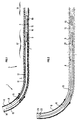
- FIG. 1 represents a production well 1 in which it is desired to carry out measurements of characteristics of fluid flow linked to the formation along the part of the well in production, these measurements having to account for variation of certain characteristics between different points of the production area of the well 1.
- This well comprises a substantially vertical part not shown and a part 3, substantially horizontal or inclined relative to the vertical, in which oil production is carried out in normal operation.
- This production zone comprises a tube 4 perforated over at least part of its length. It is through the perforations that the flow of fluid from the geological formation takes place during activation.
- the present invention proposes to obtain information on these flows and this in a differentiated manner for several locations of the production part of the well.
- Such information may be the flow rate, or the composition of the mixture produced.
- the present invention can in particular make it possible to know the flow rate as a function of the curvilinear abscissa along the production drain. Thus, for example, it is possible to determine the portions of the drain for which water is mainly produced and to intervene on these portions.
- Reference 6 designates the casing of the well in the non-production area and reference 7 designates the shoe at the end of the casing.
- a casing 8 is lowered into the well comprising a means of activating the production comprising a pump 9 and measuring equipment 10.
- the reference 12 designates the annular part between the tube 4 and the casing 8. It is in this zone that the protectors 11 are located.
- the tube 4 can be cemented (as shown in Figure 1) or not (see Figure 2).
- the pump 9 is activated by an electric motor which is integrated into it.
- This motor is powered by an electric cable 14 located in the annular zone 12, as well as in the annular zone 13 located between the casing and the casing 6 over the entire length of the casing.
- This arrangement allows the electrical connection between the motor and the cable to be made on the surface.
- the electric cable 14 is unwound on the surface as the elements constituting the casing 8 are assembled. This assembly is accompanied by an increasing penetration of the motor-pump assembly into the well.
- the casing 8 is sealed over its current length relative to the annular space 12.
- the fluid which enters the casing is that which has been treated by the pump 9.
- the intermediate zone 15 of the casing situated between the pump 9 and the measuring equipment 10 has openings 16.
- the measuring equipment 10 is traversed by the flow of fluids coming from upstream from the well, considering the direction of flow of the fluid coming from the upstream part 18 and going towards the inlet of the pump 9.
- the measuring equipment 10 can include a flow channel within it.
- the pump 9 when it is desired to carry out measurements such as flow measurements, the pump 9 is activated by supplying it with electricity by the cable 14.
- the well is activated and the pump delivers fluid from the downstream part 17 and the upstream part 18 considered in the direction of flow relative to the measuring means 10.
- the fluid coming from the downstream part 17 reaches the pump through openings 16 and the fluid coming from the upstream part 18 passes through the measuring equipment 10. Due to the existence of the openings 16, the measuring equipment 10 appreciably treats only the fraction of the effluent coming from the upstream part of the production drain. Thus, a selective measurement is obtained. It then suffices to move the pump and measuring equipment assembly by adding or removing a certain number of elements from the casing to achieve a new measurement location and perform measurements.
- FIG. 2 represents a variant of the embodiment of FIG. 1.
- the motor and pump assembly is supplied with energy by a cable 19 which runs inside the casing 20 and is connected to the motor by a bottom connector 21.
- the reference 22 designates a connector with side entry allowing the passage of the cable 19 in the annular space 23 of the well. This solution makes it possible to reduce and in certain cases to eliminate the routing of the cable in the annular space of the deviated or horizontal part of the well.
- the establishment of the cable 19 and its connection to the bottom connector is done in a conventional manner.
- a transmission of the data for example digital data obtained by the measuring equipment could be conceived using the power conductor (s) contained in the cables 9 or 19.
- FIG. 3 represents an embodiment according to which the activation pump is driven by a hydraulic fluid motor, such as a so-called “sparrow” type hydraulic lobe motor.
- a casing 24 is lowered into the well.
- This tubing has two parts.
- the first part 25 of the casing is separated from the second part of the casing 26 by a sealed element 27 such as a flange.
- annular space 29 between the second part 26 of the casing and the secondary casing communicates with the discharge orifices 30 of the pump 9. Furthermore, this annular space 29 communicates with the annular space 34 between the first part 25 of the casing and the casing by means of openings 31 made in the vicinity of the upper end of the second part 26 of the casing above the sealed element 27.
- the reference 32 designates sealing means such as cups. These cups seal between the casing 33 and the casing 24.
- annular space between the casing 33 and the casing 24 is divided into two.
- the cups 32 are located below the openings 31.
- the upper annular space 34 located between the casing 24 and the casing 33 communicates through the openings 31 with the annular space 29 located between the secondary casing 28 and the internal wall of the second part 26 of the casing 24.
- the lower annular space 35 is delimited by the casing 33, the cups 32 and the external wall of the second part 26 of the casing 24.
- the working fluid which feeds the hydraulic motor is transferred from the surface pumps 100 through the first part 25 of the casing 24, through the secondary casing, into the hydraulic motor which drives the pump 9 and is then discharged, at the same time as the fluid pumped from the drain, through the discharge orifices 30 towards the annular space 29, it passes through the openings 31 to join the upper annular space 34 and then join the surface where it can be treated by equipment 110.
- the sealed cups 32 prevent it from joining the lower annular space 35.
- the measurements made at the bottom of the well could be transmitted to the surface using pressure pulses in the circuit of the pump's working fluid (type MWD mud wave transmission).
- Reliability of production measurements and calibration sensors could be increased by simultaneously carrying out identical measurements on the part of the flow coming upstream and on that coming downstream of the production drain relative to the direction of flow.
- FIG. 4 represents an embodiment allowing in particular these measurements.
- the reference 36 designates the geological formation, the reference 37 the tube comprising perforations, the reference 38 the sealing cups. These cups make it possible to isolate the upstream part well from the flow of the downstream part.
- the reference 39 designates the measurement equipment which operates on the upstream flow, these means correspond substantially in their function to those shown in FIGS. 1, 2 and 3.
- the reference 40 designates measuring equipment which operates on the downstream flow.
- the downstream flow comes to these devices 40 through the channel 41 which communicates with the annular space 420.
- the channel 41 does not communicate with the upstream fluid having passed through the first measuring equipment 39 or upstream measuring equipment.
- the fluid coming from these upstream measuring equipment is mixed with the fluid coming from the downstream part of the drain only after this downstream fluid has passed through the downstream measuring equipment 40.
- the pump 42 delivers all of the upstream and downstream fluid.
- FIG. 4 shows a pump actuated by an electric motor powered by the cable 43.
- the measurement equipment 39 and 40 can be connected by electrical wires not shown to an electronic unit 44 used to process these different signals to transfer them to the surface by the electrical cable 43 which may include one or more electrical connections.
- the entire production from the well passes through the upstream measuring device, the cups 2 preventing the fluid from flowing according to another circuit.
- the zone 45A even if it is not cemented forms a dead end for the fluid.
- Calibration can be easily performed by comparison with wellhead measurements. Several measurement points can be obtained by varying the pump flow. If necessary, the downstream measuring device can be calibrated by imposing a circulation on the well head via the annular of the casing which can have a diameter of 24.5 cm (9. ⁇ 5 / 8).
- this device also has the advantage on the one hand of a concentration of the flow allowing a dispersed flow and a greater precision of the measurement, on the other hand eliminates any risk of circulation against the current in the well (only the flow rates at the intake of the pump are counted).
- references 45 and 46 designate absolute, relative or differential pressure sensors which are connected to the electronic unit by lines 47.
- a device making it possible to vary the pressure drops in one of the two sets of measurements or less makes it possible to minimize the error due to the leakage rate by adjusting the differential pressure to zero.
- Such a device can be adjusted by a command from the electronic unit 44 or can be autonomous.
- a sand trap 49 interposed between the strainer 50 and the impact detector makes it possible, on the one hand, to obtain a sand sampling, on the other hand, to provide a semi quantitative indication on the measurements obtained by the detector d impact, by comparing the quantity of sand to the sum of the impact count recorded.
- the sand trap consists in particular of a sand circulation circuit having a baffle shape upstream of the strainer 50.
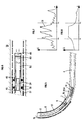
- FIGS. 7 and 8 show an example of the conclusions which the device and the method according to the present invention make it possible to obtain.
- the abscissa x represents the curvilinear abscissa along the production part of the drain.
- the ordinate of FIG. 7 represents the counts c carried out by the impact detector.
- Curve 51 represents the number of impacts (as a function of the curvilinear abscissa x. Between X1 and X2 this number is high. The integral of this curve is related substantially to the total amount of sand drained and can therefore be compared to the amount of sand collected in the sand trap 49.
- FIG. 8 the abscissa axis of which is calibrated on that of FIG. 7, represents on the ordinate a quantity Q proportional to the quantity of water collected.
- This quantity can be for example the water-cut ratio which corresponds to the quantity of water produced compared to the total quantity of liquid produced (water + oil). More simply, this quantity can be equal to the flow of water produced.
- the production operator can decide to stop the production of the drain on the portion between x1 and x2 and thus increase the quality of the production of his well.
Description
La présente invention concerne une méthode et un dispositif de diagraphie de production en puits inclinés ou horizontaux.The present invention relates to a method and a device for logging production in inclined or horizontal wells.
Il convient de souligner au préalable le rôle primordial que pourraient jouer les diagraphies de production dans la stratégie d'exploitation d'un puits pétrolier horizontal ou fortement incliné, si elles pouvaient être réalisées correctement. En effet, on admet généralement qu'un puits horizontal est susceptible de remplacer plusieurs puits verticaux (en général deux à quatre) et ceci à la fois du point de vue de la production qu'ils peuvent fournir (augmentation de l'indice de production) et de celui de la récupération (augmentation de l'aire de drainage et diminution des problèmes de formation d'un cône d'eau ou "coning").The essential role that production logging could play in the strategy of operating a horizontal or strongly inclined oil well, if it could be carried out correctly, should be emphasized beforehand. Indeed, it is generally accepted that a horizontal well is likely to replace several vertical wells (generally two to four) and this both from the point of view of the production they can supply (increase in the production index ) and that of recovery (increase in drainage area and reduction in problems of formation of a water cone or "coning").
Or, si ce double avantage reconnu au puits horizontal est valable dans le cas d'un réservoir homogène, il peut ne pas en être de même dans le cas beaucoup plus fréquent de réservoirs hétérogènes. En effet, du fait de la présence d'hétérogénéités, la production globale du puits peut devenir non rentable à cause d'une venue d'eau qui peut être caractérisée par un rapport de "water-cut (Quantité d'eau/Quantité de liquide) ou d'un rapport gaz/huile, généralement désigné en anglais par "Gas Oil Ratio" (GOR) trop important. Cette production peut devoir être réduite, par exemple pour limiter le GOR à une valeur admissible, alors même que ce problème de production peut ne provenir que d'une zone limitée du drain. Même si ce type de problèmes ne conduit pas à condamner systématiquement l'utilisation des puits horizontaux sur ce type de gisement, il est clair que le puits horizontal n'offre pas ici toute la souplesse que le producteur pourrait souhaiter pour optimiser l'exploitation du champ. Par ailleurs, il faut noter que l'ensemble de puits verticaux qui pourraient être substitués au puits horizontal offrirait plus de possibilités, le puits vertical drainant la partie du réservoir responsable du problème de production pouvant être aisément fermé sans nuire à la production des autres puits.However, if this double advantage recognized in the horizontal well is valid in the case of a homogeneous reservoir, it may not be the same in the much more frequent case of heterogeneous reservoirs. Indeed, due to the presence of heterogeneities, the overall production of the well may become unprofitable because of an inflow of water which can be characterized by a "water-cut" ratio (Quantity of water / Quantity of liquid) or a gas / oil ratio, generally referred to in English as "Gas Oil Ratio" (GOR) too high. This production may have to be reduced, for example to limit the GOR to an acceptable value, even though this production problem may only come from a limited area of the drain. Even if this type of problem does not systematically condemn the use of horizontal wells on this type of deposit, it is clear that the horizontal well does not offer here all the flexibility that the producer could wish to optimize the exploitation of the field. In addition, it should be noted that the set of vertical wells which could be substituted for the horizontal well would offer more possibilities, the vertical well draining the part of the reservoir responsible for the production problem being able to be easily closed without harming the production of the other wells .
Le moyen de contourner ce problème est évidemment l'utilisation d'une complétion sélective dans le drain horizontal, permettant soit de moduler la production zone par zone, soit de fermer la zone du drain présentant un problème.The way to get around this problem is obviously the use of selective completion in the horizontal drain, allowing either to modulate the production zone by zone, or to close the zone of the drain presenting a problem.
L'utilisation d'une complétion sélective peut être conçue à deux étapes différentes de la vie d'un puits : soit immédiatement après le forage du puits, soit ultérieurement, au moment où la nécessité de son utilisation apparaît.The use of selective completion can be designed at two different stages in the life of a well: either immediately after drilling the well, or later, when the need for its use appears.
Dans le premier cas, il est clair que la décision d'utiliser une complétion sélective est délicate et ceci pour plusieurs raisons :
- il convient tout d'abord de justifier a priori l'investissement supplémentaire que représente les équipements de complétion sélective.
- il faut ensuite définir les zones à individualiser à partir d'une description statique du réservoir.
- it is first of all advisable to justify a priori the additional investment that represents selective completion equipment.
- it is then necessary to define the zones to be individualized from a static description of the tank.
La décision différée présente l'avantage d'être prise en connaissance de cause : l'investissement supplémentaire ne sera réalisé que sur les puits qui le nécessitent et seulement au moment où cela devient nécessaire. Dans la plupart des cas, il ne sera même réalisé qu'après la période d'amortissement du puits. On peut, par ailleurs, penser pouvoir définir plus facilement les zones à isoler si on possède en plus des données dynamiques sur le réservoir, notamment par l'utilisation de diagraphies de production.The deferred decision has the advantage of being taken in full knowledge of the facts: the additional investment will be made only on the wells which require it and only when it becomes necessary. In most cases, it will not even be carried out until after the well's amortization period. We can, moreover, think that we can more easily define the zones to be isolated if we also have dynamic data on the reservoir, in particular through the use of production logs.
L'intervention peut par contre être rendue difficile, voir impossible, du fait de la complétion provisoire qui aura été utilisée pendant la première phase d'exploitation du puits, par exemple par utilisation d'un tube perforé non cimenté (généralement dénommé "liner pré-perforé" par les spécialistes).Intervention can on the other hand be made difficult, if not impossible, due to the provisional completion which will have been used during the first phase of exploitation of the well, for example by the use of a non-cemented perforated tube (generally called "pre liner" -perforated "by specialists).
D'autre part, ce mode de production (1ère phase non sélective, 2ème phase sélective) peut, dans certains cas, être la cause d'une diminution de la récupération ultime.On the other hand, this mode of production (1st non-selective phase, 2nd selective phase) can, in some cases, be the cause of a decrease in ultimate recovery.
La première solution (sélectivité dés le début de la production) paraît donc plus séduisante sur le plan technique, mais pas nécessairement sur le plan économique. La solution qui consiste à cimenter et à perforer un tube sur toute la longueur du drain, solution qui autorise par la suite toute possibilité de sélectivité, doit être écartée pour des raisons de coût dans certains cas.The first solution (selectivity from the start of production) therefore seems more attractive on a technical level, but not necessarily on an economic level. The solution which consists of cementing and perforating a tube over the entire length of the drain, a solution which subsequently allows any possibility of selectivity, must be discarded for reasons of cost in certain cases.
La meilleure solution consiste en conséquence à réaliser la première phase de production en puits découvert (en anglais "open-hole"), mais elle n'est pas toujours possible, du fait des incertitudes quant à la tenue mécanique du puits.The best solution therefore consists in carrying out the first phase of production in an open well (in English "open-hole"), but it is not always possible, due to the uncertainties as to the mechanical strength of the well.
Il en résulte que le cas de figure le plus fréquemment rencontré est celui des puits non cimentés.As a result, the most frequently encountered scenario is that of non-cemented wells.
Quelle que soit la complétion adoptée pour le puits horizontal, lorsqu'un problème de production de fluides indésirables apparaît, il devient important de pouvoir, d'une part, localiser la ou les zones éventuellement responsables de cette production, d'autre part, évaluer le potentiel du puits lorsque ces zones seront fermées.Whatever the completion adopted for the horizontal well, when a problem of production of undesirable fluids appears, it becomes important to be able, on the one hand, to locate the zone or zones possibly responsible for this production, on the other hand, to evaluate the potential of the well when these areas are closed.
Seules des diagraphies de production peuvent fournir les réponses nécessaires. Or, il se trouve que leur mise en oeuvre se heurte à des difficultés dues d'une part à l'horizontalité, d'autre part au mode de complétion.Only production logs can provide the necessary answers. However, it turns out that their implementation comes up against difficulties due on the one hand to horizontality, on the other hand to the mode of completion.
On connait par le document FR 2 519 689 une installation pour test et activation, mais on ne peut dissocier l'effluent provenant de l'amont ou de l'aval par rapport au moyen de mesure. De plus ce procédé ne convient pas aux puits inclinés ou horizontaux.Document FR 2 519 689 discloses an installation for testing and activation, but the effluent from upstream or downstream cannot be dissociated from the measurement means. In addition, this method is not suitable for inclined or horizontal wells.
Parmi, tous les modes de complétion sélective possibles (cimentation totale ou partielle, packers de formation), ou non sélective (open-hole, liner préperforé), le cas du tube perforé est celui qui cumule l'ensemble des difficultés. C'est celui qui sera considéré par la suite, les cas de mesures de production à l'intérieur d'autres complétions pouvant être obtenus en introduisant les simplifications correspondantes.Among all the possible modes of selective completion (total or partial cementing, training packers), or non-selective (open-hole, pre-perforated liner), the case of the perforated tube is that which combines all the difficulties. This is what will be considered later, the cases of production measurements within other completions can be obtained by introducing the corresponding simplifications.
Les problèmes liés aux mesures de production en puits horizontal résultent d'une combinaison de difficultés d'interprétation déjà connues en puits vertical et de difficultés propres au puits horizontaux principalement dues au mode de transport des sondes, à l'effet particulier de la gravité et au type de complétion propre à ce type de puits (diamètre de liner important, liner souvent non cimenté, etc.....)The problems related to horizontal well production measurements result from a combination of interpretation difficulties already known in vertical wells and difficulties specific to horizontal wells mainly due to the mode of transport of the probes, the particular effect of gravity and the type of completion specific to this type of well (large liner diameter, often non-cemented liner, etc ...)
La présente invention concerne le cas où le puits est non éruptif et doit être activé pour produire.The present invention relates to the case where the well is non-eruptive and must be activated to produce.
La présente invention peut également être appliquée aux puits verticaux.The present invention can also be applied to vertical wells.
Le but essentiel d'une diagraphie de production est de fournir le profil de débit de chaque phase le long du drain. Ce résultat est obtenu par la réalisation et l'interprétation d'une ou de plusieurs mesures effectuées dans le puits.The essential purpose of a production log is to provide the flow profile of each phase along the drain. This result is obtained by carrying out and interpreting one or more measurements made in the well.
Les principales mesures courantes sont :
- mesure de type "spinner". Les appareils de ce type fournissent la vitesse de rotation d'une hélice entraînée par l'écoulement. La mesure dépend en conséquence essentiellement de la vitesse d'écoulement du fluide, mais aussi de sa viscosité.The main common measures are:
- "spinner" type measurement. Devices of this type provide the rotational speed of a propeller driven by the flow. The measurement therefore depends essentially on the flow speed of the fluid, but also on its viscosity.
Les problèmes liés à ce type de mesure proviennent essentiellement de l'hétérogénéité du champ de vitesse dans une section transversale du puits, de la nature stratifiée de l'écoulement, d'une éventuelle différence des vitesses d'écoulement de chaque phase, de possibles mouvements à contre-courant, par exemple avec un débit à contresens derrière le tube (cas de complétion non cimentée) ou, si un écoulement dispersé peut être obtenu, de la nécessité de connaître la composition du fluide en chaque phase et la viscosité du mélange.The problems associated with this type of measurement arise essentially from the heterogeneity of the velocity field in a cross section of the well, from the stratified nature of the flow, from a possible difference in the flow velocities of each phase, from possible counter-current movements, for example with a flow in the opposite direction behind the tube (case of non-cemented completion) or, if a dispersed flow can be obtained, the need to know the composition of the fluid in each phase and the viscosity of the mixture .
Des outils ont été conçus pour résoudre au moins en partie certains de ces problèmes notamment des débimètres à hélice : FBS (Full Bore Spinner), des débimètres à pétales.Tools have been designed to at least partially solve some of these problems, in particular propeller flow meters: FBS (Full Bore Spinner), petal flow meters.
Même dans le cas du débitmètre à pétales, il subsiste le problème de l'écoulement derrière le tube (dans le sens de l'écoulement général, ou à contre-courant) et le problème de l'étalonnage de la réponse de l'hélice.
- mesure par traceur radioactif. Il s'agit là d'une mesure directe de vitesse d'écoulement. Les problèmes signalés plus haut concernant la complexité de l'écoulement des fluides restent valables. Il convient de signaler le dèveloppement actuel d'outils utilisant des traceurs préférentiellement solubles dans l'huile et des traceurs préférentiellement solubles dans l'eau.
- mesure de densité. Le principe de mesure pouvant être utilisé en puits horizontal est une absorption de rayons γ . Ces mesures rencontrent généralement un problème d'étalonnage, de représentativité de la mesure (la mesure n'intègre pas toute la section de l'écoulement) et de différence entre la composition du fluide dans le puits et celle du fluide en écoulement (water hold-up). En ce qui concerne ce dernier point, il convient de signaler une particularité des puits horizontaux le problème de rétention de la phase lourde, notamment de l'eau (désignée en anglais par "water hold-up") se rencontre chaque fois que la gravité s'exerce en sens contraire de l'écoulement (puits vertical, dévié α < 90°, α étant l'angle d'inclinaison du puits sur la verticale). Par contre dans le cas où la gravité agit dans le sens d'écoulement (puits horizontal α > 90°) il est probable que l'on rencontrera un phénomène de rétention de la phase légère, tel le gaz.
- mesure de teneur en eau par mesure de la constante diélectrique. La réponse de ce type d'outil nécessite un étalonnage et dépend très fortement de la nature de l'écoulement (dispersion d'une phase dans l'autre).Even in the case of the petal flow meter, there remains the problem of the flow behind the tube (in the general flow direction, or against the current) and the problem of the calibration of the propeller response .
- measurement by radioactive tracer. This is a direct measurement of flow velocity. The problems mentioned above concerning the complexity of the flow of fluids remain valid. Mention should be made of the current development of tools using tracers preferentially soluble in oil and tracers preferentially soluble in water.
- density measurement. The principle of measurement that can be used in a horizontal well is an absorption of γ rays. These measurements generally encounter a problem of calibration, representativeness of the measurement (the measurement does not include the entire section of the flow) and the difference between the composition of the fluid in the well and that of the fluid in flow (water hold -up). With regard to this last point, it is worth pointing out a peculiarity of horizontal wells the problem of retention of the heavy phase, in particular of water (designated in English by "water hold-up") is encountered whenever gravity works in the opposite direction of the flow (vertical well, deviated α <90 °, α being the angle of inclination of the well on the vertical). On the other hand, in the case where gravity acts in the direction of flow (horizontal well α> 90 °) it is likely that we will encounter a phenomenon of retention of the light phase, such as gas.
- measurement of water content by measurement of the dielectric constant. The response of this type of tool requires calibration and very much depends on the nature of the flow (dispersion from one phase to the other).
Pour toutes ces mesures, la présence de particules solides risque de poser de plus des problèmes importants, entre autres détérioration des hélices de débitmètre.For all these measurements, the presence of solid particles may also pose significant problems, among other things deterioration of the flowmeter propellers.
Il convient de signaler d'autres mesures, telles les mesures de pressions et de températures.Other measures should be noted, such as pressure and temperature measurements.
Selon la présente invention on utilise un tubage, généralement désigné en anglais par "tubing" pour descendre les outils de mesure.According to the present invention, a casing is used, generally designated in English by "tubing" for lowering the measuring tools.
On en arrive alors à la conception d'un système modulaire de mesures de production en puits horizontaux dont la composition est à définir en fonction du puits, de sa complétion et de la nature des fluides produits. Si la mise en oeuvre d'un tel système est a priori plus lourde et plus complexe que celle d'une diagraphie de production classique, il convient de remarquer que, d'une part, une telle diagraphie classique ne peut pas offrir suffisamment de précision et que, d'autre part, ces mesures n'interviendront que lorsqu'une intervention sélective (complétion sélective ou traitement sélectif) deviendra nécessaire et imposera de toute façon un déséquipement du puits.We then arrive at the design of a modular system of production measurements in horizontal wells whose composition is to be defined according to the well, its completion and the nature of the fluids produced. If the implementation of such a system is a priori heavier and more complex than that of a conventional production log, it should be noted that, on the one hand, such a conventional log cannot offer sufficient precision. and that, on the other hand, these measures will only intervene when a selective intervention (selective completion or selective treatment) becomes necessary and will in any case impose a disequipping of the well.
La mise en oeuvre d'une diagraphie de production à l'aide de tubings suppose pour en simplifier l'interprétation que la répartition des pressions dans le drain n'est pas trop modifiée par la position du train de tubage (tubing) dans le drain, c'est-à-dire que les pertes de charge dans l'annulaire compris entre le tubage (tubing) et le tube perforé sont négligeables. Ce point peut être vérifié en cours de mesures pour l'utilisation d'un ou de capteur(s) de pression évaluant la perte de charge dans l'annulaire.The implementation of a production log using tubings supposes to simplify the interpretation that the distribution of pressures in the drain is not too modified by the position of the casing train (tubing) in the drain , that is to say that the pressure drops in the annular between the casing and the perforated tube are negligible. This point can be checked during measurements for the use of a pressure sensor (s) evaluating the pressure drop in the ring finger.
Selon la présente invention on active le puits pour effectuer les mesures. Pour ce faire on peut équiper le tubage à l'aide d'une pompe permettant l'activation du puits. Pour des raisons de simplification de mise en oeuvre, le mode d'entrainement de la pompe sera alors soit électrique, soit hydraulique (turbopompe ou pompe à jet).According to the present invention, the well is activated to carry out the measurements. To do this, the casing can be fitted using a pump enabling the well to be activated. For reasons of simplification of implementation, the drive mode of the pump will then be either electric or hydraulic (turbopump or jet pump).
Ainsi la présente invention concerne un procédé pour effectuer des diagraphies de production dans un puits non éruptif ayant ou non une partie inclinée ou horizontale. Ce procédé comprend la mise en place d'au moins un moyen de mesure en amont d'un moyen d'activation, p.e. d'une pompe, l'activation du puits pour provoquer la production d'effluents provenant des deux cotés amont et aval par rapport audit moyen de mesure et le traitement par ledit moyen de mesure d'une partie au moins de l'effluent provenant de la partie du puits en amont dudit moyen de mesure.Thus the present invention relates to a method for performing production logs in a non-eruptive well having or not an inclined or horizontal part. This process includes the installation of at least one measurement means upstream of an activation means, eg a pump, the activation of the well to cause the production of effluents from both upstream and downstream sides with respect to said measuring means and the treatment by said measuring means of at least part of the effluent coming from the part of the well upstream of said measuring means.
On pourra traiter par un deuxième moyen de mesure une partie au moins de l'écoulement provenant de l'aval relativement audit premier moyen de mesure.It will be possible to treat by a second measuring means at least part of the flow coming from downstream relative to said first measuring means.
Le premier moyen de mesure pourra traiter sensiblement l'ensemble de l'écoulement amont.The first measurement means can deal substantially with the entire upstream flow.
Le deuxième moyen de mesure pourra traiter sensiblement l'ensemble de l'écoulement aval.The second measurement means will be able to process substantially all of the downstream flow.
On pourra contrôler la différence de pression existant dans l'annulaire du puits de production de part et d'autre du premier moyen de mesure.It will be possible to check the pressure difference existing in the annular of the production well on either side of the first measuring means.
De même, on pourra effectuer des bilans de conservation notamment des débits d'une ou plusieurs phases.Likewise, conservation reports may be carried out, in particular debits from one or more phases.
On pourra étalonner le premier moyen de mesure en éliminant l'écoulement aval.The first measurement means can be calibrated by eliminating the downstream flow.
La présente invention concerne également un dispositif pour effectuer des diagraphies de production dans un puits non éruptif, ce dispositif comporte des moyens d'activation pour activer la production du puits, au moins un moyen de mesure, ce moyen étant placé en amont dudit moyen d'activation, des moyens de connexions comportant au moins une ouverture entre les moyens d'activation et ledit moyen de mesure, le moyen de mesure étant adapté à traiter au moins une partie de l'effluent provenant de l'amont du moyen de mesure.The present invention also relates to a device for carrying out production logs in a non-eruptive well, this device comprises activation means for activating the production of the well, at least one measuring means, this means being placed upstream of said means. activation, connection means comprising at least one opening between the activation means and said measuring means, the measuring means being adapted to treat at least part of the effluent coming from upstream of the measuring means.
Le dispositif pourra comporter un deuxième moyen de mesure qui pourra traiter au moins une partie de l'écoulement aval, l'entrée de ce deuxième moyen de mesure étant reliée à ladite ouverture.The device may include a second measuring means which can treat at least part of the downstream flow, the inlet of this second measuring means being connected to said opening.
Le dispositif pourra en outre comporter des moyens pour séparer l'écoulement provenant de l'amont de l'écoulement provenant de l'aval, relativement audit premier moyen de mesure.The device may also include means for separating the flow coming from upstream from the flow coming from downstream, relative to said first measuring means.
Le dispositif pourra comporter des moyens de mesure des pressions ou des différences de pression de part et d'autre dudit premier moyen de mesure.The device may include means for measuring pressures or pressure differences on either side of said first measuring means.
Le dispositif pourra comporter des moyens de réglage de la différence de pression régnant dans l'annulaire du puits de part et d'autre dudit premier moyen de mesure.The device may include means for adjusting the pressure difference prevailing in the annulus of the well on either side of said first measuring means.
Les moyens de mesures des pressions pourront mesurer cette différence de pression et l'une au moins des pression amont ou aval régnant dans l'annulaire du puits de part et d'autre du premier moyen de mesure.The pressure measurement means can measure this pressure difference and at least one of the upstream or downstream pressure prevailing in the annular of the well on either side of the first measurement means.
Les moyens d'activation pourront comporter un moteur électrique ou un moteur hydraulique.The activation means may include an electric motor or a hydraulic motor.
Les moyens d'activation, et les moyens de mesure pourront être fixés à l'extrémité d'un tubage.The activation means and the measurement means may be fixed to the end of a casing.
Les moyens d'activation pourront comporter un moteur hydraulique alimenté par un tubage secondaire placé dans ledit tubage.The activation means may include a hydraulic motor powered by a secondary casing placed in said casing.
Le dispositif et le procédé selon la présente invention s'appliquent aux puits verticaux, inclines ou horizontaux.The device and method according to the present invention apply to vertical, inclined or horizontal wells.
On pourra transmettre des informations du fond du puits par des ondes électromagnétiques, par onde de boue ou par câble électrique.Information can be transmitted from the bottom of the well by electromagnetic waves, by mud wave or by electric cable.
Le dispositif selon l'invention pourra comporter des moyens de trasmission d'information par ondes électromagnétiques.The device according to the invention may include means for transmitting information by electromagnetic waves.
La présente invention sera mieux comprise et ses avantages apparaîtront plus clairement à la description qui suit d'exemples particuliers nullement limitatifs illustrés par les figures ci-jointes en annexe par lesquelles :
- les figures 1 et 2 représentent des modes de réalisation comportant une pompe d'activation électrique,
- la figure 3 illustre un mode de réalisation comportant une pompe d'activation hydraulique,
- la figure 4 montre la disposition des ensembles de mesure relativement au schéma d'écoulement des fluides,
- la figure 5 représente la position du tubage dans une position permettant le calage ou étalonnage d'éléments de mesures,
- la figure 6 représente un équipement pour la détection des venues de sable, et
- les figures 7
et 8 montrent des courbes relatives aux venues de sable et d'eau.
- FIGS. 1 and 2 represent embodiments comprising an electric activation pump,
- FIG. 3 illustrates an embodiment comprising a hydraulic activation pump,
- FIG. 4 shows the arrangement of the measuring assemblies relative to the flow diagram of the fluids,
- FIG. 5 represents the position of the casing in a position allowing the calibration or calibration of measurement elements,
- FIG. 6 represents an equipment for detecting the coming of sand, and
- Figures 7 and 8 show curves relating to the inflow of sand and water.
Dans les exemples donnés ci-après, les moyens d'étanchéité sont placés sensiblement au même niveau que les premiers moyens de mesure.In the examples given below, the sealing means are placed substantially at the same level as the first measuring means.
La figure 1 représente un puits de production 1 dans lequel on souhaite effectuer des mesures de caractéristiques d'écoulement de fluide liées à la formation le long de la partie du puits en production, ces mesures devant rendre compte de variation de certaines caractéristiques entre différents points de la zone de production du puits 1. Ce puits comporte une partie sensiblement verticale non représentée et une partie 3, sensiblement horizontale ou inclinée par rapport à la verticale, dans laquelle est réalisée en fonctionnement normal la production pétrolière.FIG. 1 represents a production well 1 in which it is desired to carry out measurements of characteristics of fluid flow linked to the formation along the part of the well in production, these measurements having to account for variation of certain characteristics between different points of the production area of the well 1. This well comprises a substantially vertical part not shown and a
Cette zone de production comporte un tube 4 perforé sur au moins une partie de sa longueur. C'est à travers les perforations que s'effectuent en cours d'activation les écoulements de fluide en provenance de la formation géologique 5.This production zone comprises a
La présente invention propose d'obtenir des informations sur ces écoulements et cela d'une manière différenciée pour plusieurs endroits de la partie de production du puits.The present invention proposes to obtain information on these flows and this in a differentiated manner for several locations of the production part of the well.
De telles informations peuvent être le débit, ou la composition du mélange produit. La présente invention peut permettre notamment de connaître le débit en fonction de l'abscisse curviligne le long de drain de production. Ainsi, par exemple, il est possible de déterminer les portions du drain pour lesquelles on produit essentiellement de l'eau et d'intervenir sur ces portions.Such information may be the flow rate, or the composition of the mixture produced. The present invention can in particular make it possible to know the flow rate as a function of the curvilinear abscissa along the production drain. Thus, for example, it is possible to determine the portions of the drain for which water is mainly produced and to intervene on these portions.
La référence 6 désigne le cuvelage du puits dans la zone de non production et la référence 7 le sabot à l'extrêmité du cuvelage.
Selon la présente invention on descend dans le puits un tubage 8 comportant un moyen d'activation de la production comportant une pompe 9 et un équipement de mesure 10.According to the present invention, a
Pour cette solution il est recommandé d'utiliser des protecteurs ou centreurs 11 dans la partie déviée et horizontale du puits.For this solution it is recommended to use protectors or
La référence 12 désigne la partie annulaire entre le tube 4 et le tubage 8. C'est dans cette zone que sont situés les protecteurs 11.The
Le tube 4 peut être cimenté (comme représenté à la figure 1) ou non (cf. figure 2).The
Dans le cas de la figure 1, la pompe 9 est activée par un moteur électrique qui lui est intégré. Ce moteur est alimenté par un câble électrique 14 situé dans la zone annulaire 12, ainsi que dans la zone annulaire 13 située entre le tubage et le cuvelage 6 sur toute la longueur du tubage. Cette disposition permet de réaliser en surface la connexion électrique entre le moteur et le câble. Le câble électrique 14 est déroulé en surface au fur et à mesure de l'assemblage des éléments qui constituent le tubage 8. Cet assemblage s'accompagne d'une pénétration de plus en plus grande de l'ensemble moteur-pompe dans le puits.In the case of FIG. 1, the
Le tubage 8 est étanche sur sa longueur courante relativement à l'espace annulaire 12. Le fluide qui pénètre dans le tubage est celui qui a été traité par la pompe 9.The
La zone intermédiaire 15 du tubage située entre la pompe 9 et l'équipement de mesure 10 comporte des ouvertures 16.The
Les équipements de mesure 10 sont traversés par l'écoulement des fluides provenant de l'amont du puits en considérant le sens de l'écoulement du fluide provenant de la partie amont 18 et se dirigeant vers l'entrée de la pompe 9.The measuring
Ainsi l'équipement de mesure 10 peut comporter un canal d'écoulement en son sein.Thus the measuring
Selon ce mode de réalisation lorsque l'on désire effectuer des mesures telles des mesures de débit on active la pompe 9 en l'alimentant en électricité par le câble 14.According to this embodiment when it is desired to carry out measurements such as flow measurements, the
Dans ces conditions le puits est activé et la pompe refoule du fluide provenant de la partie aval 17 et de la partie amont 18 considérée dans le sens de l'écoulement relativement aux moyens de mesure 10.Under these conditions, the well is activated and the pump delivers fluid from the
Le fluide en provenance de la partie aval 17 parvient à la pompe par des ouvertures 16 et le fluide provenant de la partie amont 18 passe par l'équipement de mesure 10. Du fait de l'existence des ouvertures 16, les équipements de mesure 10 ne traite sensiblement que la fraction de l'effluent provenant de la partie amont du drain de production. Ainsi, l'on obtient une mesure sélective. Il suffit alors de déplacer l'ensemble pompe et équipement de mesure en ajoutant ou en retirant un certain nombre d'éléments du tubage pour atteindre un nouvel emplacement de mesure et d'effectuer des mesures.The fluid coming from the
L'établissement de bilan notamment de débit permet de connaître l'évolution de certaines caractéristiques le long du drain de production. Ainsi, il est possible de connaître en fonction de l'abscisse curviligne du drain le débit local de la formation et sa composition en eau, gaz, huile....The establishment of a balance sheet, in particular of flow, allows us to know the evolution of certain characteristics along the production drain. Thus, it is possible to know according to the curvilinear abscissa of the drain the local flow of the formation and its composition in water, gas, oil ...
La figure 2 représente une variante du mode de réalisation de la figure 1.FIG. 2 represents a variant of the embodiment of FIG. 1.
Sur la figure 2 l'ensemble moteur et pompe est alimenté en énergie par un câble 19 qui chemine à l'intérieur du tubage 20 et est connecté au moteur par un connecteur de fond 21.In FIG. 2, the motor and pump assembly is supplied with energy by a
La référence 22 désigne un raccord à entrée latérale permettant le passage du câble 19 dans l'espace annulaire 23 du puits. Cette solution permet de réduire et dans certains cas de supprimer le cheminement du câble dans l'espace annulaire de la partie déviée ou horizontale du puits.The
La mise en place du câble 19 et sa connexion au connecteur de fond se fait de manière classique.The establishment of the
Dans le cas d'un pompage électrique on pourrait concevoir une transmission des données par exemple numériques obtenues par l'équipement de mesure en utilisant le ou les conducteurs de puissance contenus dans les câbles 9 ou 19.In the case of an electric pumping, a transmission of the data, for example digital data obtained by the measuring equipment could be conceived using the power conductor (s) contained in the
La figure 3 représente un mode de réalisation suivant lequel la pompe d'activation est entraînée par un moteur à fluide hydraulique, tel un moteur hydraulique à lobes dits du type "Moineau".FIG. 3 represents an embodiment according to which the activation pump is driven by a hydraulic fluid motor, such as a so-called "sparrow" type hydraulic lobe motor.
Selon ce mode de réalisation un tubage 24 est descendu dans le puits. Ce tubage comporte deux parties. La première partie 25 du tubage est séparée de la deuxième partie du tubage 26 par un élément étanche 27 tel qu'une bride.According to this embodiment, a
Un tubage secondaire 28, éventuellement souple et enroulable du type "coiled tubing", relie la première partie du tubage 25 au moteur hydraulique de la pompe 9 à travers la deuxième partie 26 du tubage.A
L'espace annulaire 29 compris entre la deuxième partie 26 du tubage et le tubage secondaire communique avec les orifices 30 de refoulement de la pompe 9. Par ailleurs, cet espace annulaire 29 communique avec l'espace annulaire 34 compris entre la première partie 25 du tubage et le cuvelage par l'intermédiaire d'ouvertures 31 pratiquées au voisinage de l'extrémité supérieure de la deuxième partie 26 du tubage au dessus de l'élément étanche 27.The
La référence 32 désigne des moyens d'étanchéité tels que des coupelles. Ces coupelles réalisent l'étanchéité entre le cuvelage 33 et le tubage 24.The
Ainsi l'espace annulaire entre le cuvelage 33 et le tubage 24 est partagé en deux.Thus the annular space between the casing 33 and the
Les coupelles 32 sont situées en dessous des ouvertures 31. Ainsi l'espace annulaire supérieur 34 situé entre le tubage 24 et le cuvelage 33 communique par les ouvertures 31 avec l'espace annulaire 29 situé entre le tubage secondaire 28 et la paroi interne de la deuxième partie 26 du tubage 24.The
L'espace annulaire inférieur 35 est délimité par le cuvelage 33, les coupelles 32 et la paroi externe de la deuxième partie 26 du tubage 24.The lower
La partie située sous la pompe 9, c'est-à-dire la zone intermédiaire et l'équipement de mesure sont sensiblement identiques à ceux des figures 1 et 2, d'ailleurs les éléments communs portent les mêmes références.The part located under the
Dans ce mode de réalisation le fluide moteur qui alimente le moteur hydraulique est transféré depuis les pompes 100 de surface à travers la première partie 25 du tubage 24, à travers le tubage secondaire, dans le moteur hydraulique qui entraîne la pompe 9 puis est refoulé, en même temps que le fluide pompé en provenance du drain, à travers les orifices de refoulement 30 vers l'espace annulaire 29, il passe à travers les ouvertures 31 pour rejoindre l'espace annulaire supérieur 34 et rejoindre ensuite la surface ou il peut être traité par des équipements 110. Bien entendu, les coupelles étanches 32 l'empêchent de rejoindre l'espace annulaire inférieur 35.In this embodiment, the working fluid which feeds the hydraulic motor is transferred from the surface pumps 100 through the
Dans le cas de ce type de pompage les mesures effectuées au fond du puits pourraient être transmises en surface à l'aide d'impulsions de pression dans le circuit du fluide moteur de la pompe (type transmission par ondes de boue MWD).In the case of this type of pumping, the measurements made at the bottom of the well could be transmitted to the surface using pressure pulses in the circuit of the pump's working fluid (type MWD mud wave transmission).
La fiabilité des mesures de production et de l'étalonnage des capteurs pourrait être accrue en effectuant simultanément des mesures identiques sur la partie du débit provenant de l'amont et sur celle provenant de l'aval du drain de production relativement au sens de l'écoulement.Reliability of production measurements and calibration sensors could be increased by simultaneously carrying out identical measurements on the part of the flow coming upstream and on that coming downstream of the production drain relative to the direction of flow.
La figure 4 représente un mode de réalisation permettant notamment ces mesures.FIG. 4 represents an embodiment allowing in particular these measurements.
La référence 36 désigne la formation géologique, la référence 37 le tube comportant des perforations, la référence 38 les coupelles d'étanchéité. Ces coupelles permettent de bien isoler la partie amont de l'écoulement de la partie aval.The
La référence 39 désigne les équipements de mesure qui opèrent sur l'écoulement amont, ces moyens correspondent sensiblement dans leur fonction à ceux représentés aux figures 1, 2 et 3.The
La référence 40 désigne des équipements de mesure qui opèrent sur l'écoulement aval. L'écoulement aval provient à ces équipements 40 par le canal 41 qui communique avec l'espace annulaire 420.The
Le canal 41 ne communique pas avec le fluide amont ayant traversé les premiers équipements de mesure 39 ou équipements de mesure amont. Le fluide provenant de ces équipements de mesure amont n'est mélangé au fluide provenant de la partie aval du drain qu'après que ce fluide aval ait traversé les équipements de mesure aval 40.The
La pompe 42 refoule l'ensemble du fluide amont et aval.The
Sur la figure 4 a été représentée une pompe actionnée par un moteur électrique alimenté par le câble 43.FIG. 4 shows a pump actuated by an electric motor powered by the
Les équipements de mesures 39 et 40 peuvent être reliés par des fils électriques non représentés à un boîtier électronique 44 servant à traiter ces différents signaux pour les transférer vers la surface par le câble électrique 43 qui peut comporter une ou plusieurs liaisons électriques.The
La comparaison des mesures de fond avec les mesures effectuées en tête de puits ramenées en condition de fond permet une vérification des mesures et leur validation par l'établissement de bilans (conservation des débits de chaque phase).The comparison of the bottom measurements with the measurements carried out at the wellhead brought back into bottom condition allows a verification of the measurements and their validation by the establishment of balances (conservation of the flows of each phase).
La présence de mesures redondantes et des conditions simples de continuité des débits de chaque phase en cours de déplacement du dispositif dans le puits peut permettre un étalonnage direct de l'ensemble de mesures. Une autre possibilité consiste à faire varier le débit total sans déplacer l'ensemble de mesures.The presence of redundant measurements and simple conditions of continuity of the flows of each phase during moving the device in the well can allow direct calibration of the measurement set. Another possibility is to vary the total flow without moving the set of measurements.
Enfin, il existe une possibilité particulièrement intéressante du point de vue de l'étalonnage des outils, lorsque cet ensemble représenté à la figure 4 est positionné au niveau de la tête du tube perforé, à un endroit ou ce tube n'est pas encore perforé (voir figure 5).Finally, there is a particularly advantageous possibility from the point of view of tool calibration, when this assembly shown in FIG. 4 is positioned at the head of the perforated tube, at a place where this tube is not yet perforated. (see figure 5).
En effet, dans ce cas, toute la production du puits traverse le dispositif de mesure amont, les coupelles 2 empêchant le fluide de s'écouler selon un autre circuit. La zone 45A même si elle n'est pas cimentée forme un cul-de-sac pour le fluide. L'étalonnage peut être réalisé facilement par comparaison avec les mesures en tête de puits. Plusieurs points de mesure peuvent être obtenus en faisant variér le débit de la pompe. Si nécessaire, le dispositif de mesure aval peut être étalonné en imposant à la tête de puits une circulation par l'intermédiaire de l'annulaire du tubage qui peut avoir un diamètre de 24,5 cm (9.˝5/8).In fact, in this case, the entire production from the well passes through the upstream measuring device, the cups 2 preventing the fluid from flowing according to another circuit. The
On peut remarquer que ce dispositif présente par ailleurs l'avantage d'une part d'une concentration du débit permettant un écoulement dispersé et une plus grande précision de la mesure, d'autre part élimine tout risque de circulation à contre-courant dans le puits (seuls les débits à l'admission de la pompe sont comptabilisés).It can be noted that this device also has the advantage on the one hand of a concentration of the flow allowing a dispersed flow and a greater precision of the measurement, on the other hand eliminates any risk of circulation against the current in the well (only the flow rates at the intake of the pump are counted).
Dans le cas d'une mesure à l'intérieur d'un tube perforé non cimenté, une erreur peut intervenir du fait d'une circulation derrière le tube (une partie du débit aval pris en compte par le débitmètre amont ou inversement).In the case of a measurement inside a non-cemented perforated tube, an error can occur due to a circulation behind the tube (part of the downstream flow taken into account by the upstream flow meter or vice versa).
On peut, dans un premier temps, penser obtenir une indication qualitative d'une telle circulation derrière le tube perforé en disposant d'une mesure de pression différentielle entre les entrées des deux dispositifs de mesure amont et aval.We can, at first, think of obtaining a qualitative indication of such circulation behind the perforated tube by having a differential pressure measurement between the inputs of the two upstream and downstream measuring devices.
Cette mesure fournit en fait le sens de la fuite derrière le liner, mais ne peut donner aucune indication sur la valeur de débit de fluide. On peut cependant admettre que ce débit de fuite est proportionnel à cette différence de pression QF = αΔp. Il sera donc nul si les pertes de charge dans les deux dispositifs de mesure sont identiques.This measurement actually provides the direction of leakage behind the liner, but cannot give any indication of the value of fluid flow. It can however be assumed that this leakage rate is proportional to this pressure difference Q F = αΔp. It will therefore zero if the pressure drops in the two measuring devices are identical.
Sur la figure 4 les références 45 et 46 désignent des capteurs de pression absolues, relatives ou différentielles qui sont connectés au boîtier électronique par des lignes 47.In FIG. 4, the
L'utilisation d'un dispositif permettant de faire varier les pertes de charge dans l'un des deux ensembles de mesures ou moins permet de minimiser l'erreur due au débit de fuite en ajustant la pression différentielle à zéro. Un tel dispositif peut être réglé par une commande provenant du boîtier électronique 44 ou peut être autonome.The use of a device making it possible to vary the pressure drops in one of the two sets of measurements or less makes it possible to minimize the error due to the leakage rate by adjusting the differential pressure to zero. Such a device can be adjusted by a command from the
Les caractéristiques de la fuite derrière le tube perforé pourraient être évaluée de la manière suivante :
- positionnement de l'ensemble dans le drain.
- débit de la pompe QT
- mesure des débits amont et aval et de la pression après avoir ajusté le dispositif mentionné ci-dessus pour régler la pression différentielle à une valeur nulle.

- fermeture complète du débitmètre aval. Cela suppose que les moyens de mesure aval 40 comportent un moyen d'obstruction télécommandé.
- ajustement du débit de la pompe de façon à obtenir la même pression dans la partie amont du drain. Nouveau débit Q′T = Q′am . Mesure de la pression différentielle ΔP
- La caractéristique de la fuite est alors déterminée par

- positioning of the assembly in the drain.
- pump flow Q T
- measurement of the upstream and downstream flows and of the pressure after having adjusted the device mentioned above to adjust the differential pressure to a zero value.
- complete closure of the downstream flowmeter. This assumes that the downstream measurement means 40 comprise a remote-controlled obstruction means.
- adjustment of the pump flow so as to obtain the same pressure in the upstream part of the drain. New flow Q ′ T = Q ′ am . Differential pressure measurement Δ P
- The characteristic of the leak is then determined by
Par ailleurs, on peut chercher, par un système d'étranglement de l'un des deux circuits amont ou aval, à provoquer une perte de charge artificielle de la mesure et déterminer la fuite à partir des mesures, notamment des pressions et des débits amont et aval.Furthermore, one can seek, by a throttling system of one of the two upstream or downstream circuits, to cause an artificial pressure drop in the measurement and determine the leak from the measurements, in particular of the pressures and flow rates upstream. and downstream.
La présence de particules solides (sable) dans le débit de production est susceptible de poser un problème au niveau des instruments de mesure, d'une part, au niveau de la pompe, d'autre part. Par ailleurs, la détermination d'éventuelles zones de production de sable d'extension limitée pourrait être intéressante dans la mesure où elle permettrait l'utilisation d'un procédé de contrôle de sable sur une longueur limitée de sable (possibilité d'utilisation d'un procédé de consolidation chimique, longueur de crépine limitée entraînant un coût plus faible et moins de risques de colmatage).The presence of solid particles (sand) in the production flow is likely to pose a problem with the measuring instruments, on the one hand, with the pump, on the other hand go. Furthermore, the determination of possible areas for the production of sand of limited extension could be advantageous insofar as it would allow the use of a process for controlling sand over a limited length of sand (possibility of using a chemical consolidation process, limited strainer length resulting in a lower cost and less risk of clogging).
La mise en place en aval des outils de mesure d'une crépine constituerait une protection des instruments de mesure.Putting down a strainer measurement tool downstream would protect the measuring instruments.
La détection de production de sable pourrait être obtenue à l'aide d'un détecteur d'impact 48 ("Noise Log") proposé par la plupart des sociétés de diagraphies.The detection of sand production could be obtained using an impact detector 48 ("Noise Log") proposed by most of the logging companies.
Un piège à sable 49 intercalé entre la crépine 50 et le détecteur d'impact permet, d'une part, d'obtenir un échantillonnage de sable, d'autre part, de fournir une indication semi quantitative sur les mesures obtenues par le détecteur d'impact, en comparant la quantité de sable à la somme du compte d'impacts enregistrés.A
Sur la figure 6, le piège à sable est constitué notamment par un circuit de circulation du sable ayant une forme de chicane en amont de la crépine 50.In FIG. 6, the sand trap consists in particular of a sand circulation circuit having a baffle shape upstream of the
Les figures 7 et 8 montrent un exemple des conclusions que permet d'obtenir le dispositif et le procédé selon la présente invention.FIGS. 7 and 8 show an example of the conclusions which the device and the method according to the present invention make it possible to obtain.
Sur ces figures 7 l'abscisse x représente l'abscisse curviligne le long de la partie de production du drain. L'ordonnée de la figure 7 représente les comptages c effectués par le détecteur d'impacts. La courbe 51 représente le nombre d'impacts (en fonction de l'abscisse curviligne x. Entre X1 et X2 ce nombre est élevé. L'intégrale de cette courbe est liée sensiblement à la quantité totale de sable draînée et peut donc être rapprochée de la quantité de sable recueillie dans le piège à sable 49.In these figures 7 the abscissa x represents the curvilinear abscissa along the production part of the drain. The ordinate of FIG. 7 represents the counts c carried out by the impact detector.
La figure 8 dont l'axe des abscisses est calé sur celui de la figure 7 représente en ordonnées une grandeur Q proportionnelle à la quantité d'eau recueillie. Cette grandeur peut être par exemple le rapport de water-cut qui correspond à la quantité d'eau produite rapportée à la quantité totale de liquide produit (eau+ huile). Plus simplement cette grandeur peut être égale au débit d'eau produit.FIG. 8, the abscissa axis of which is calibrated on that of FIG. 7, represents on the ordinate a quantity Q proportional to the quantity of water collected. This quantity can be for example the water-cut ratio which corresponds to the quantity of water produced compared to the total quantity of liquid produced (water + oil). More simply, this quantity can be equal to the flow of water produced.
Sur la figure 8 cette grandeur Q indique une forte augmentation entre x1 et x2 qui correspond à la zone où l'on constate une importante venue de sable.In Figure 8 this quantity Q indicates a strong increase between x1 and x2 which corresponds to the area where there is a significant influx of sand.
Ainsi à ces résultats, l'opérateur de production peut décider d'arrêter la production du drain sur la portion comprise entre x1 et x2 et ainsi augmenter la qualité de la production de son puits.Thus with these results, the production operator can decide to stop the production of the drain on the portion between x1 and x2 and thus increase the quality of the production of his well.
Il a été décrit jusqu'à présent deux modes de transmission des informations à partir du fond du puits l'un étant la transmission par câble électrique et l'autre par onde de boue.Two modes of information transmission from the bottom of the well have so far been described, one being transmission by electric cable and the other by mud wave.
On ne sortira pas du cadre de la présente invention en utilisant une transmission par onde électromagnétique tel que décrit dans l'article de MM. P. de GAUQUE et R. GRUDZINSKI intitulé "Propagation of Electromagnetic Waves along a Drillstring of Finite conductivity" paru dans la revue SPE Drilling Engineering de Juin 1987. De même on ne sortira pas du cadre de la présente invention en combinant certains de ces différents moyens de transmission.It will not depart from the scope of the present invention to use an electromagnetic wave transmission as described in the article by MM. P. de GAUQUE and R. GRUDZINSKI entitled "Propagation of Electromagnetic Waves along a Drillstring of Finite conductivity" published in the review SPE Drilling Engineering from June 1987. Similarly, we will not depart from the scope of the present invention by combining some of these different means of transmission.
Claims (19)
Applications Claiming Priority (4)
| Application Number | Priority Date | Filing Date | Title |
|---|---|---|---|
| FR8813605A FR2637939B1 (en) | 1988-10-14 | 1988-10-14 | METHOD AND DEVICE FOR NON-ERUPTIVE PRODUCTION WELL LOGGING |
| FR8813605 | 1988-10-14 | ||
| FR8904225 | 1989-03-29 | ||
| FR8904225 | 1989-03-29 |
Publications (2)
| Publication Number | Publication Date |
|---|---|
| EP0364362A1 EP0364362A1 (en) | 1990-04-18 |
| EP0364362B1 true EP0364362B1 (en) | 1992-07-08 |
Family
ID=26226934
Family Applications (1)
| Application Number | Title | Priority Date | Filing Date |
|---|---|---|---|
| EP89402813A Expired - Lifetime EP0364362B1 (en) | 1988-10-14 | 1989-10-12 | Method and device for logging non-eruptive wells |
Country Status (5)
| Country | Link |
|---|---|
| US (1) | US5042297A (en) |
| EP (1) | EP0364362B1 (en) |
| CA (1) | CA2000665C (en) |
| DK (1) | DK506389A (en) |
| NO (1) | NO178083C (en) |
Families Citing this family (41)
| Publication number | Priority date | Publication date | Assignee | Title |
|---|---|---|---|---|
| DE68914283D1 (en) * | 1989-09-14 | 1994-05-05 | Schlumberger Ltd | Method and device for measuring in the borehole below a pump. |
| FR2668795B1 (en) * | 1990-11-02 | 1993-01-08 | Inst Francais Du Petrole | METHOD FOR PROMOTING THE PRODUCTION OF EFFLUENTS FROM A PRODUCTION AREA. |
| GB9025230D0 (en) * | 1990-11-20 | 1991-01-02 | Framo Dev Ltd | Well completion system |
| US5163515A (en) * | 1991-04-23 | 1992-11-17 | Den Norske Stats Oljeselskap A.S | Pumpdown toolstring operations in horizontal or high-deviation oil or gas wells |
| FR2677701B1 (en) * | 1991-06-11 | 1993-09-03 | Inst Francais Du Petrole | METHOD FOR CONTINUING MEASUREMENTS AFTER THE RECOVERY OF A MEASURING TOOL IMMOBILIZED IN A WELL. |
| US5284208A (en) * | 1992-10-15 | 1994-02-08 | Halliburton Company | Production logging system using through flow line tools |
| FR2683590B1 (en) * | 1991-11-13 | 1993-12-31 | Institut Francais Petrole | MEASURING AND INTERVENTION DEVICE IN A WELL, ASSEMBLY METHOD AND USE IN AN OIL WELL. |
| US5477923A (en) * | 1992-08-07 | 1995-12-26 | Baker Hughes Incorporated | Wellbore completion using measurement-while-drilling techniques |
| US5452761A (en) * | 1994-10-31 | 1995-09-26 | Western Atlas International, Inc. | Synchronized digital stacking method and application to induction logging tools |
| US6101871A (en) * | 1995-02-28 | 2000-08-15 | Sandra K. Myers | In-ground vapor monitoring device and method |
| US5884701A (en) * | 1997-07-18 | 1999-03-23 | Schlumberger Technology Corpporation | Dual downhole injection system utilizing coiled tubing |
| FR2776769B1 (en) * | 1998-03-30 | 2000-04-28 | Schlumberger Services Petrol | METHOD AND INSTALLATION FOR IMPLEMENTING A MULTIPHASIC FLOWMETER, DOWNSTREAM OF A OIL WELL |
| US7185700B2 (en) * | 2004-06-14 | 2007-03-06 | Weatherford/Lamb, Inc. | Separable plug for use with a wellbore tool |
| US7407006B2 (en) * | 1999-01-04 | 2008-08-05 | Weatherford/Lamb, Inc. | System for logging formations surrounding a wellbore |
| US7513305B2 (en) * | 1999-01-04 | 2009-04-07 | Weatherford/Lamb, Inc. | Apparatus and methods for operating a tool in a wellbore |
| US6279660B1 (en) * | 1999-08-05 | 2001-08-28 | Cidra Corporation | Apparatus for optimizing production of multi-phase fluid |
| GB2363809B (en) * | 2000-06-21 | 2003-04-02 | Schlumberger Holdings | Chemical sensor for wellbore applications |
| CA2444657C (en) | 2001-04-23 | 2007-10-16 | Weatherford/Lamb, Inc. | Apparatus and methods for conveying instrumentation within a borehole using continuous sucker rod |
| US7155967B2 (en) * | 2002-07-09 | 2007-01-02 | Schlumberger Technology Corporation | Formation testing apparatus and method |
| US7350569B2 (en) * | 2004-06-14 | 2008-04-01 | Weatherford/Lamb, Inc. | Separable plug for use in a wellbore |
| US7891420B2 (en) * | 2005-09-30 | 2011-02-22 | Exxonmobil Upstream Research Company | Wellbore apparatus and method for completion, production and injection |
| US9982519B2 (en) | 2014-07-14 | 2018-05-29 | Saudi Arabian Oil Company | Flow meter well tool |
| BR112018070565A2 (en) | 2016-04-07 | 2019-02-12 | Bp Exploration Operating Company Limited | downhole event detection using acoustic frequency domain characteristics |
| EP3670830B1 (en) * | 2016-04-07 | 2021-08-11 | BP Exploration Operating Company Limited | Detecting downhole events using acoustic frequency domain features |
| EP3608503B1 (en) | 2017-03-31 | 2022-05-04 | BP Exploration Operating Company Limited | Well and overburden monitoring using distributed acoustic sensors |
| CN107044273B (en) * | 2017-04-07 | 2018-06-22 | 中国石油大学(华东) | Sand control pit shaft blocking-de-plugging integration evaluation experimental simulator and method |
| WO2019038401A1 (en) | 2017-08-23 | 2019-02-28 | Bp Exploration Operating Company Limited | Detecting downhole sand ingress locations |
| EA202090867A1 (en) | 2017-10-11 | 2020-09-04 | Бп Эксплорейшн Оперейтинг Компани Лимитед | DETECTING EVENTS USING FEATURES IN THE AREA OF ACOUSTIC FREQUENCIES |
| US10982515B2 (en) * | 2018-05-23 | 2021-04-20 | Intrinsic Energy Technology, LLC | Electric submersible hydraulic lift pump system |
| EP3887648B1 (en) | 2018-11-29 | 2024-01-03 | BP Exploration Operating Company Limited | Das data processing to identify fluid inflow locations and fluid type |
| GB201820331D0 (en) | 2018-12-13 | 2019-01-30 | Bp Exploration Operating Co Ltd | Distributed acoustic sensing autocalibration |
| US10920586B2 (en) | 2018-12-28 | 2021-02-16 | Saudi Arabian Oil Company | Systems and methods for logging while treating |
| WO2021073741A1 (en) | 2019-10-17 | 2021-04-22 | Lytt Limited | Fluid inflow characterization using hybrid das/dts measurements |
| CA3154435C (en) | 2019-10-17 | 2023-03-28 | Lytt Limited | Inflow detection using dts features |
| WO2021093974A1 (en) | 2019-11-15 | 2021-05-20 | Lytt Limited | Systems and methods for draw down improvements across wellbores |
| US11255160B2 (en) | 2019-12-09 | 2022-02-22 | Saudi Arabian Oil Company | Unblocking wellbores |
| WO2021249643A1 (en) | 2020-06-11 | 2021-12-16 | Lytt Limited | Systems and methods for subterranean fluid flow characterization |
| EP4168647A1 (en) | 2020-06-18 | 2023-04-26 | Lytt Limited | Event model training using in situ data |
| US11352867B2 (en) | 2020-08-26 | 2022-06-07 | Saudi Arabian Oil Company | Enhanced hydrocarbon recovery with electric current |
| US11608723B2 (en) | 2021-01-04 | 2023-03-21 | Saudi Arabian Oil Company | Stimulated water injection processes for injectivity improvement |
| US11421148B1 (en) | 2021-05-04 | 2022-08-23 | Saudi Arabian Oil Company | Injection of tailored water chemistry to mitigate foaming agents retention on reservoir formation surface |
Family Cites Families (12)
| Publication number | Priority date | Publication date | Assignee | Title |
|---|---|---|---|---|
| US3123708A (en) * | 1964-03-03 | Well production method using radioactive | ||
| US2379138A (en) * | 1943-01-11 | 1945-06-26 | Shell Dev | Annular flow measuring device |
| US2688872A (en) * | 1949-06-08 | 1954-09-14 | Stanolind Oil & Gas Co | Apparatus for fluid entry logging |
| US3059695A (en) * | 1960-03-07 | 1962-10-23 | Jersey Prod Res Co | Drill stem testing device |
| FR1322402A (en) * | 1962-03-20 | 1963-03-29 | Petroleum Res Corp | Multiple terrain layer analysis system |
| US3283570A (en) * | 1963-06-26 | 1966-11-08 | Sun Oil Co | Production measurement in multiple completion wells |
| US4006630A (en) * | 1976-05-26 | 1977-02-08 | Atlantic Richfield Company | Well testing apparatus |
| SU691723A1 (en) * | 1977-07-20 | 1979-10-15 | Северо-Кавказский Государственный Научно-Исследовательский И Проектный Институт Нефтяной Промышленности | Apparatus for sampling a liquid |
| US4222438A (en) * | 1978-10-30 | 1980-09-16 | Standard Oil Company (Indiana) | Reservoir fluid sampling method and apparatus |
| FR2519689A1 (en) * | 1982-01-12 | 1983-07-18 | Elf Aquitaine | INSTALLATION FOR TESTING A WELL WITH A IMMERED PUMP AND METHOD FOR ITS IMPLEMENTATION |
| US4453599A (en) * | 1982-05-10 | 1984-06-12 | Otis Engineering Corporation | Method and apparatus for controlling a well |
| SU1244162A1 (en) * | 1984-06-22 | 1986-07-15 | Азербайджанский Институт Нефти И Химии Им.М.Азизбекова | Method of intervalwise measurement of drilling mud viscosity |
-
1989
- 1989-10-12 NO NO894084A patent/NO178083C/en not_active IP Right Cessation
- 1989-10-12 EP EP89402813A patent/EP0364362B1/en not_active Expired - Lifetime
- 1989-10-12 DK DK506389A patent/DK506389A/en not_active Application Discontinuation
- 1989-10-13 CA CA002000665A patent/CA2000665C/en not_active Expired - Fee Related
- 1989-10-16 US US07/422,105 patent/US5042297A/en not_active Expired - Lifetime
Also Published As
| Publication number | Publication date |
|---|---|
| US5042297A (en) | 1991-08-27 |
| EP0364362A1 (en) | 1990-04-18 |
| DK506389D0 (en) | 1989-10-12 |
| NO178083B (en) | 1995-10-09 |
| CA2000665A1 (en) | 1990-04-14 |
| CA2000665C (en) | 1999-12-28 |
| NO894084L (en) | 1990-04-17 |
| DK506389A (en) | 1990-04-15 |
| NO178083C (en) | 1996-01-17 |
| NO894084D0 (en) | 1989-10-12 |
Similar Documents
| Publication | Publication Date | Title |
|---|---|---|
| EP0364362B1 (en) | Method and device for logging non-eruptive wells | |
| EP0251881B1 (en) | Enhanced recovery method to continually produce a fluid contained in a geological formation | |
| US8622128B2 (en) | In-situ evaluation of reservoir sanding and fines migration and related completion, lift and surface facilities design | |
| RU2354827C2 (en) | Bench estimation device and method | |
| FR2910922A1 (en) | PUMP CONTROL FOR LAYER TESTING | |
| FR2751373A1 (en) | IMPROVEMENT IN FLUID CIRCULATION APPARATUS | |
| FR2885166A1 (en) | METHOD AND APPARATUS FOR ANALYZING FLUIDS | |
| AU2001292062B2 (en) | Improved well testing system | |
| US6554065B2 (en) | Memory gravel pack imaging apparatus and method | |
| FR2467414A1 (en) | METHOD AND DEVICE FOR RECOGNIZING SOILS AND ROCKY MEDIA | |
| FR2562151A1 (en) | METHOD AND APPARATUS FOR DETERMINING PRESSURE IN FORMATIONS CROSSED BY A SURVEY | |
| FR3086779A1 (en) | MATCHING AN AUTOMATED PRODUCTION HISTORY USING BAYESIAN OPTIMIZATION | |
| FR3061235B1 (en) | DOWNHOLE TOOL WITH FILTER DEVICE | |
| US6164127A (en) | Well flowmeter and down-hole sampler | |
| WO1993019354A1 (en) | Process for chemical logging of a liquid and plant for carrying out said process | |
| EP0435727B1 (en) | Method and device for stimulation of an underground formation by injection of a fluid coming from an adjacent zone being connected to the first one by a drain hole transversing a low-permeable intermediate layer | |
| CA1124102A (en) | Device for simultaneous measurement of drilling fluid parameters | |
| FR2706526A1 (en) | Method and system for early detection of the jamming of a device for collecting carrot samples in a borehole and taking palliative measures. | |
| FR2637939A1 (en) | Method and device for logging in a non-eruptive oil-production well | |
| EP0461963B1 (en) | Method and device for logging non-eruptive wells | |
| CA2012772C (en) | Method and device for production logging in flowing well | |
| EP0465316B1 (en) | Apparatus for stimulating production and for logging for non-eruptive wells | |
| WO2003098000A1 (en) | Method for determining by strata reserve quality of an oil well | |
| EP0231708B1 (en) | Apparatus and method for determining the orientation of fractures in a geological formation | |
| FR2976313A1 (en) | METHOD FOR DETERMINING THE COMPLEX RESPONSE OF A PERMEABLE STRATE |
Legal Events
| Date | Code | Title | Description |
|---|---|---|---|
| PUAI | Public reference made under article 153(3) epc to a published international application that has entered the european phase |
Free format text: ORIGINAL CODE: 0009012 |
|
| 17P | Request for examination filed |
Effective date: 19891021 |
|
| AK | Designated contracting states |
Kind code of ref document: A1 Designated state(s): FR GB IT NL |
|
| 17Q | First examination report despatched |
Effective date: 19910425 |
|
| ITF | It: translation for a ep patent filed |
Owner name: DE DOMINICIS & MAYER S.R.L. |
|
| GRAA | (expected) grant |
Free format text: ORIGINAL CODE: 0009210 |
|
| AK | Designated contracting states |
Kind code of ref document: B1 Designated state(s): FR GB IT NL |
|
| GBT | Gb: translation of ep patent filed (gb section 77(6)(a)/1977) | ||
| PLBE | No opposition filed within time limit |
Free format text: ORIGINAL CODE: 0009261 |
|
| STAA | Information on the status of an ep patent application or granted ep patent |
Free format text: STATUS: NO OPPOSITION FILED WITHIN TIME LIMIT |
|
| 26N | No opposition filed | ||
| REG | Reference to a national code |
Ref country code: GB Ref legal event code: IF02 |
|
| PGFP | Annual fee paid to national office [announced via postgrant information from national office to epo] |
Ref country code: GB Payment date: 20031006 Year of fee payment: 15 |
|
| PGFP | Annual fee paid to national office [announced via postgrant information from national office to epo] |
Ref country code: FR Payment date: 20031015 Year of fee payment: 15 |
|
| PGFP | Annual fee paid to national office [announced via postgrant information from national office to epo] |
Ref country code: NL Payment date: 20031031 Year of fee payment: 15 |
|
| PG25 | Lapsed in a contracting state [announced via postgrant information from national office to epo] |
Ref country code: GB Free format text: LAPSE BECAUSE OF NON-PAYMENT OF DUE FEES Effective date: 20041012 |
|
| PG25 | Lapsed in a contracting state [announced via postgrant information from national office to epo] |
Ref country code: NL Free format text: LAPSE BECAUSE OF NON-PAYMENT OF DUE FEES Effective date: 20050501 |
|
| GBPC | Gb: european patent ceased through non-payment of renewal fee |
Effective date: 20041012 |
|
| PG25 | Lapsed in a contracting state [announced via postgrant information from national office to epo] |
Ref country code: FR Free format text: LAPSE BECAUSE OF NON-PAYMENT OF DUE FEES Effective date: 20050630 |
|
| NLV4 | Nl: lapsed or anulled due to non-payment of the annual fee |
Effective date: 20050501 |
|
| REG | Reference to a national code |
Ref country code: FR Ref legal event code: ST |
|
| PG25 | Lapsed in a contracting state [announced via postgrant information from national office to epo] |
Ref country code: IT Free format text: LAPSE BECAUSE OF NON-PAYMENT OF DUE FEES;WARNING: LAPSES OF ITALIAN PATENTS WITH EFFECTIVE DATE BEFORE 2007 MAY HAVE OCCURRED AT ANY TIME BEFORE 2007. THE CORRECT EFFECTIVE DATE MAY BE DIFFERENT FROM THE ONE RECORDED. Effective date: 20051012 |