EP0363981B1 - Automatic masking device - Google Patents
Automatic masking device Download PDFInfo
- Publication number
- EP0363981B1 EP0363981B1 EP89119068A EP89119068A EP0363981B1 EP 0363981 B1 EP0363981 B1 EP 0363981B1 EP 89119068 A EP89119068 A EP 89119068A EP 89119068 A EP89119068 A EP 89119068A EP 0363981 B1 EP0363981 B1 EP 0363981B1
- Authority
- EP
- European Patent Office
- Prior art keywords
- plate
- bars
- masking device
- mask opening
- light transmitting
- Prior art date
- Legal status (The legal status is an assumption and is not a legal conclusion. Google has not performed a legal analysis and makes no representation as to the accuracy of the status listed.)
- Expired - Lifetime
Links
Images


Classifications
-
- G—PHYSICS
- G03—PHOTOGRAPHY; CINEMATOGRAPHY; ANALOGOUS TECHNIQUES USING WAVES OTHER THAN OPTICAL WAVES; ELECTROGRAPHY; HOLOGRAPHY
- G03B—APPARATUS OR ARRANGEMENTS FOR TAKING PHOTOGRAPHS OR FOR PROJECTING OR VIEWING THEM; APPARATUS OR ARRANGEMENTS EMPLOYING ANALOGOUS TECHNIQUES USING WAVES OTHER THAN OPTICAL WAVES; ACCESSORIES THEREFOR
- G03B27/00—Photographic printing apparatus
- G03B27/02—Exposure apparatus for contact printing
- G03B27/14—Details
- G03B27/28—Edge-masking devices
Definitions
- the present invention relates to an automatic masking device employed in a composer, composing camera and the like used for multi-duplication during the process of reproduction. More specifically, the present invention relates to an automatic masking device enabling precise exposure of there area defined by masks.
- Fig. 10 is a plan view showing the automatic masking device disclosed in this article and Figs. 11A and 11B are cross sections of the portion shown by the lines XIA-XIA and XIB-XIB of Fig. 10.
- the conventional automatic masking device comprises 4 masking units 110 respectively arranged at respective end surfaces of a rectangular transparent plate 105.
- Each of the masking units 110 comprises a roll shaft 111 arranged in parallel to each of the end surfaces of the transparent plate 105, two pairs of flexible non-transparent masking sheets 112a and 112b arranged in intersecting directions, a moving block 124 for moving tip end portions of the masking sheets 112a and 112b to cover the transparent plate 105, a driving screw 123 for guiding the moving block 124 and the reversible motor 124 for driving the driving screw 123.
- the masking sheets 112a and 112b are wound around the roll shaft 111 forming winding rollers 111a and 111b. The sheets are large enough to cover from one end to the other end of the transparent plate 105 when they are yielded.
- Leading edges 113a and 113b for defining end portions of the masking sheets 112a and 112b are provided at end portions of the respective masking sheets 112a and 112b.
- a mask opening M Y in the front and rear directions is defined by portions 114b facing a pair of leading edges 113b in the front and rear directions, while portions facing a pair of leading edges 113a in the left and right directions define the mask opening M X in the left and right directions.
- the leading edges 113a and 113b are made of thick and rigid plate material so that the masking sheets 112a and 112b can be yielded against the rolling-back force of the roll shaft 111.
- a masking device in a composer for example, a horizontal composer comprises two pairs of masking sheets 112a and 112b arranged above the transparent plate 105. Plate making is carried out in the following manner by this device.
- An original film S is placed at a prescribed position on the transparent plate 105, as shown by a chain dotted line in Fig. 10.
- the two pairs of masking sheets 112a and 112b are arranged on the transparent plate 105 to cover four end surfaces of the original film S.
- a photosensitive material such as a PS plate P is placed below the transparent plate 105 and under the original film S. Light is emitted from a light source provided above the transparent plate 105 in this state.
- an image of the original film S is formed on the photosensitive surface such as the PS plate P in contact with the original film S through the mask opening M (defined by M X and M Y ) formed on the transparent plate 105.
- the masking sheets 112a and 112b are arranged such that a different unexposed area only is opened. Thereafter, the image of the original film S is formed on the photosensitive material through the same operations. By repeating the same process, a plurality of the images of the original film S are formed on the photosensitive surface P.
- the transparent plate 105 has some thickness, the dimension of the mask opening (M X and M Y ) and the dimension of an area to be exposed (E X , E Y ) do not coincide with each other. Consequently, blurring due to the diffraction of the light from the light source inevitably occurs around the area to be exposed E X , E Y on the photosensitive surface (see Figs. 11A and 11B).
- the leading edges 113a and 113b are formed of thick plate material (about 3 mm).
- the distance between the masking sheet 112a and the original film S is the sum of the thickness of the transparent plate 115, the thickness of the masking sheet 112b (about 0.2 mm) and the thickness (about 3 mm) of the leading edge 113b. Consequently, images are blurred at broader areas around the area E X to be exposed defined by the leading edge 113a.
- one object of the present invention which is defined in claim 1, is to reduce areas in which images are blurred around the area to be exposed in a masking device.
- Another object of the present invention is to make thinner the leading edge which is to be in contact with the transparent plate.
- a further object of the present invention is to divide an end portion of the leading edge into a portion supporting the masking sheet and a portion defining the area to be exposed in an automatic masking device.
- a masking device for masking areas which are not to be exposed of a photosensitive material when images of an original are to be exposed on the photosensitive material comprising a transparent plate provided on the original, having a pair of end portions in a first direction and a pair of end portions in a second direction intersecting the first direction; a pair of first light intercepting devices having one end fixed close to one end portion of the transparent plate in the fist direction for covering the transparent plate from both sides in the first direction ; and a pair of second light intercepting devices having one end fixed close to one end portion of the transparent plate in the second direction for masking the transparent plate from both sides in the second direction.
- the first light intercepting device comprises a first cover for covering the transparent plate and a member for defining an end portion, different from the one end, in the first direction of the first cover.
- the end portion defining member comprises a first cover holding device and a member for defining an opening in the first direction arranged close to the transparent plate. There is a first space between the first cover holding member and the member for defining the opening in the first direction.
- the second light intercepting device comprises a second cover for covering the transparent plate and a member for defining an end portion in the second direction for defining the other end, different from the said one end, in the second direction of the second cover.
- the member for defining the end portion in the second direction comprises a second cover holding device for holding the end portion of the second cover and a member for defining an opening in the second direction.
- the member for defining the opening portion in the second direction is provided at least to pass through the first space.
- the member for defining the end portion in the first direction is divided into a first cover holding member and a member for defining an opening portion in the first direction.
- the first cover holding member receives tension of the first cover and the member for defining the opening portion in the first direction does not receive any force, and therefore, it is formed of a thin plate.
- the member for defining the end portion in the second direction is provided adjacent to and above the member for defining the opening portion in the first direction which is formed of a thin plate.
- the conveyor type multiple image printing machine comprises a printing table 2 which can be elevated and lowered provided on an upper surface of a body 1; a transparent plate 5 on a lower surface of an edge frame 4; an upper frame 3 which can be opened and closed provided on the printing table 2; a masking device 10 provided on the side of the upper surface of the transparent plate 5 which will be described later; an original film conveying belt 6 provided movable in the X-Y directions in the figure in relation to the printing table 2; an evacuating apparatus (not shown) for vacuum contact; and a light source 8 for printing.
- An original film S is positioned by means of the original conveying belt 6 in relation to the photosensitive material P such as a PS plate placed on the printing table 2.
- the image of the original S is formed on the photosensitive material P in this state, and the film S is moved to another position. In this manner, the film S is successively positioned by means of the original conveying belt 6, so that a plurality of the images of the original S are printed on the photosensitive material P.
- the upper frame 3 can be moved by an air cylinder 7 to a full open attitude A, a half open attitude B and a closed attitude C, as shown in Fig. 6.
- Exchange of the photosensitive material P or the original S is carried out in the full open attitude A.
- the original S is moved in the X-Y directions by the operation of the belt 6 to be positioned on the photosensitive material P in the half open attitude B.
- the original S is brought into contact with the photosensitive material P for printing in the closed attitude C.
- the original conveying belt 6 is wound around pulleys arranged in the left and right side of the printing table 2 to surround the printing table 2.
- the original conveying belt is movable also in the front end rear directions (Y) of the printing table 2.
- the original film has a front edge fixed on the original conveying belt 6 by means of a sticky tape and the film moves in the X-Y directions in relation to the photosensitive material positioned and placed on the printing table 2 to be positioned at a prescribed position of the photosensitive material P.
- the printing table 2 is a little lowered and air is emitted from an air nozzle 9 so as to prevent the rear end of the original S from being suspended and in contact with the photosensitive material.
- the upper frame 3 is closed so that the original is in contact with the photosensitive material P.
- the masking device 10 is operated to form a desired mask opening. Printing is carried out through the mask opening.
- the masking device 10 comprises two pairs of retractable masking sheets 12a, 12a (12b, 12b) which adjustably define a mask opening M X in the left and right directions and a mask opening M Y in the front and rear directions.
- the size of the opening M defined by M X and M Y is selected to be little smaller than the size of the original S, as described with reference to Fig. 9.
- the retractable masking sheets 12a ⁇ 12b are retractably wound around rollers 11a and 11b, respectively. Tip ends thereof are respectively fixed to leading edges 13a and 13b and the mask opening M is defined to have prescribed dimensions M X and M Y by a mask driving mechanism.
- the mask driving mechanism comprises a driving motor 20 through a driving gear; endless transmission belts 23 wound around driving pulleys 21 and driven pulleys 22 of a pair of roll shafts 11 ⁇ 11; and moving blocks 24a ⁇ 24b for the leading edge fixed on the endless transmission belt 23.
- a driving motor 20 through a driving gear
- endless transmission belts 23 wound around driving pulleys 21 and driven pulleys 22 of a pair of roll shafts 11 ⁇ 11
- moving blocks 24a ⁇ 24b for the leading edge fixed on the endless transmission belt 23.
- the leading edges 13a ⁇ 13b of the masking sheets 12a ⁇ 12b comprise mask opening defining plates 14a formed of a thin plate arranged close to the transparent plate 5 for defining the mask opening M X in the left and right directions, and masking sheet leading plates 15a retractably fixing the masking sheet 12a.
- the masking sheet leading plate 15a and the mask opening defining plate 14a are separated into an upper part and a lower part.
- Mask opening defining plates 14b of the other pair of leading edges 13b ⁇ 13b are arranged intersecting the upper part of the mask opening defining plate 14a.
- the masking sheet 12a is rolled up by the shaft 11 by means of a rolling spring, not shown, and a constant tension is applied thereto.
- the tension is applied only to the masking sheet leading plate 15a and not to the mask opening defining plate 14a. Therefore, the mask opening defining plate 14a can be made of a relatively thin plate member (for example having the thickness of 0.6 to 0.8 mm).
- the mask opening defining plate 14a is supported movable in up and down directions by means of a suspension 26 fixed to the moving block 24a.
- the defining plate 14a When the defining plate 14a is moved, the lower surface thereof is in contact with the upper surface of the transparent plate 5, and the defining plate 14a is adapted to move along the bend of the transparent plate 5. Structured in this manner, the mask opening defining plate 14a will not be lift away from the upper surface of the transparent plate 5. Therefore, there is no possibility of the area in which images are blurred being extended in the periphery of the mask opening defining plate 14a.
- the moving block 24a is moved along a guide bar 25.
- a pair of leading edges 13b ⁇ 13b defining the mask opening M Y in the front end rear directions also comprise mask opening defining plates 14b and masking sheet leading plates 15b, as shown in Fig. 1.
- the both are arranged separately in the upper and lower parts.
- the mask opening defining plate 14b is formed of a thin plate member which is supported movable in the up and down directions by the moving block 24b. Namely, the tension applied to the masking sheet 12b works on only the masking sheet leading plate 15b and not the mask opening defining plate 14b.
- the leading edges 13b (including 14b and 15b) defining the opening portion M Y in the front and rear direction is arranged close to the mask opening defining plate 14a which is formed of a thin plate member (having the thickness of about 0.6 to 0.8 mm) defining the opening portion M X in the left and right directions arranged in contact with the transparent plate 5.
- the thickness of the mask opening defining plate 14b in the left and right directions which influences the size of the area in which images are blurred in the periphery of the area E Y to be exposed in the front and rear directions is made about 1/4 to 1/5 of a conventional one (about 3.2 mm, see 112b + 113b in Fig. 11B). Consequently, as shown in Fig. 4B, there remains little possibility of the area in which images are blurred extending near the periphery of the area E Y to be exposed in the front and rear directions.
- the above described pair of leading edges 13b ⁇ 13b may be formed integrally by a thick plate member and they need not be separated into the mask opening defining plate 14b and the masking sheet leading plate 15b.
- the edge side (mask opening defining portion) defining the mask opening M Y may be arranged near and upper the mask opening defining plate 14a which is separately arranged as described above (see Fig. 4C).
- the mask opening defining plate 14b When the pair of leading edges 13b ⁇ 13b are separated into the mask opening defining plate 14b and the masking sheet leading plate 15b, only the mask opening defining plate 14b may be arranged between the mask opening defining plate 14a and the masking sheet leading plate 15a of the other pair of leading edges 13a ⁇ 13a and the masking sheet leading plate 15b may be arranged above the other masking sheet leading plate 15a.
- the present invention is especially advantageous when applied to a masking device which requires large light shading area.
- the reason for this is that even when the rolling up force applied to the masking sheet is large, the mask opening defining plate can be formed of a thin plate member.
- a horizontal composer to which the masking device for the present invention is applied comprises a printing table 36 holding a photosensitive material P and an original table 32 provided relatively movable in parallel to the surface of the photosensitive material P on the printing table 36.
- the original table 32 moves in the Y direction, as shown, on a Y axis table 33, and the Y axis table 33 moves in the X direction, as shown, on the printing table 36, whereby the original table 32 is moved to an arbitrary position on the photosensitive material P in parallel to the surface of the photosensitive material P.
- the original table 32 comprises a printing light source 8 provided above and a transparent plate (not shown) holding an original film at the bottom portion thereof.
- the automatic masking device is also provided on the transparent plate.
- the structure of the automatic masking device is the same as that applied to the above described conveyor type multiple image printing machine, so that the description thereof is not repeated.
- the original table 32 comprises the automatic masking device 10 and a transparent plate (that is, an original holder) 5 provided therebelow.
- the automatic masking device 10 is moved upward and downward together with the transparent plate 5 by means of an elevating apparatus, not shown, in the original table 32. Therefore, the original film S can be brought into contact with the photosensitive material P held on the lower surface of the transparent plate 5. Generally, the original film S is attracted and held by a vacuum groove provided on the periphery of the lower surface of the transparent plate 5.
- a biasing spring should be preferably be provided so that the mask opening defining plates 14a and 14b abut the transparent plate 5 of the original holder.
- the reason for this is as follows.
- the masking device 10 is arranged horizontally as shown in Fig. 3 in a horizontal composer, so that the opening defining plate 14a comes into contact with the transparent plate 5 by the weight of the defining plate 14a itself.
- the automatic masking device is arranged vertically. Since the transparent plate 5 is arranged erected vertically, the opening defining plate 14a does not come into contact with the transparent plate 5 by the weight of itself. Therefore, a biasing spring should be provided which forces the defining operate 14a to the transparent plate 5 to be in contact therewith.
- At least a pair of leading edges comprise a mask opening defining plate and a masking sheet leading plate and the two plates are arranged separately such that the tension of the masking sheet does not work on the mask opening defining plate. Accordingly, the mask opening defining plate arranged adjacent to transparent plate can be made thin. Therefore, even when the mask opening defining portion of the other pair of leading edges is arranged adjacent to and intersecting with the upper side of the mask opening defining plate, the area in which images are blurred near the periphery of the area to be exposed caused by the other pair of the mask opening defining portions will not be so large as in the prior art.
Landscapes
- Physics & Mathematics (AREA)
- General Physics & Mathematics (AREA)
- Exposure And Positioning Against Photoresist Photosensitive Materials (AREA)
Description
- The present invention relates to an automatic masking device employed in a composer, composing camera and the like used for multi-duplication during the process of reproduction. More specifically, the present invention relates to an automatic masking device enabling precise exposure of there area defined by masks.
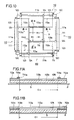
- An automatic masking device of interest to the present invention is disclosed in Japanese Utility Model Laying-Open No. 60-140960. Fig. 10 is a plan view showing the automatic masking device disclosed in this article and Figs. 11A and 11B are cross sections of the portion shown by the lines XIA-XIA and XIB-XIB of Fig. 10. Referring to Figs. 10, 11A and 11B, the conventional automatic masking device comprises 4
masking units 110 respectively arranged at respective end surfaces of a rectangulartransparent plate 105. Each of themasking units 110 comprises aroll shaft 111 arranged in parallel to each of the end surfaces of thetransparent plate 105, two pairs of flexiblenon-transparent masking sheets block 124 for moving tip end portions of themasking sheets transparent plate 105, adriving screw 123 for guiding the movingblock 124 and thereversible motor 124 for driving thedriving screw 123. Themasking sheets roll shaft 111 formingwinding rollers transparent plate 105 when they are yielded.Leading edges masking sheets respective masking sheets edges 113b in the front and rear directions, while portions facing a pair of leadingedges 113a in the left and right directions define the mask opening MX in the left and right directions. The leadingedges masking sheets roll shaft 111. - Generally, a masking device in a composer, for example, a horizontal composer comprises two pairs of
masking sheets transparent plate 105. Plate making is carried out in the following manner by this device. An original film S is placed at a prescribed position on thetransparent plate 105, as shown by a chain dotted line in Fig. 10. The two pairs ofmasking sheets transparent plate 105 to cover four end surfaces of the original film S. A photosensitive material such as a PS plate P is placed below thetransparent plate 105 and under the original film S. Light is emitted from a light source provided above thetransparent plate 105 in this state. Consequently, an image of the original film S is formed on the photosensitive surface such as the PS plate P in contact with the original film S through the mask opening M (defined by MX and MY) formed on thetransparent plate 105. After the image of the original film S is formed at a prescribed position, themasking sheets - As described above, in a composer or the like, a plurality of originals are formed on the transparent surface P with end surfaces thereof common to each other. Therefore, it is necessary to prevent blurring due to diffraction of the light at end surface portions of each of the originals.
- However, since the
transparent plate 105 has some thickness, the dimension of the mask opening (MX and MY) and the dimension of an area to be exposed (EX, EY) do not coincide with each other. Consequently, blurring due to the diffraction of the light from the light source inevitably occurs around the area to be exposed EX, EY on the photosensitive surface (see Figs. 11A and 11B). - In the above described conventional device, the leading
edges edges 113a are arranged intersecting with and over the other pair of leadingedges 113b arranged close to thetransparent plate 105, the distance between themasking sheet 112a and the original film S is the sum of the thickness of the transparent plate 115, the thickness of themasking sheet 112b (about 0.2 mm) and the thickness (about 3 mm) of the leadingedge 113b. Consequently, images are blurred at broader areas around the area EX to be exposed defined by the leadingedge 113a. - Therefore, one object of the present invention which is defined in
claim 1, is to reduce areas in which images are blurred around the area to be exposed in a masking device. - Another object of the present invention is to make thinner the leading edge which is to be in contact with the transparent plate.
- A further object of the present invention is to divide an end portion of the leading edge into a portion supporting the masking sheet and a portion defining the area to be exposed in an automatic masking device.
- The above described objects of the present invention can be attained by a masking device for masking areas which are not to be exposed of a photosensitive material when images of an original are to be exposed on the photosensitive material, comprising a transparent plate provided on the original, having a pair of end portions in a first direction and a pair of end portions in a second direction intersecting the first direction; a pair of first light intercepting devices having one end fixed close to one end portion of the transparent plate in the fist direction for covering the transparent plate from both sides in the first direction ; and a pair of second light intercepting devices having one end fixed close to one end portion of the transparent plate in the second direction for masking the transparent plate from both sides in the second direction. The first light intercepting device comprises a first cover for covering the transparent plate and a member for defining an end portion, different from the one end, in the first direction of the first cover. The end portion defining member comprises a first cover holding device and a member for defining an opening in the first direction arranged close to the transparent plate. There is a first space between the first cover holding member and the member for defining the opening in the first direction. The second light intercepting device comprises a second cover for covering the transparent plate and a member for defining an end portion in the second direction for defining the other end, different from the said one end, in the second direction of the second cover. The member for defining the end portion in the second direction comprises a second cover holding device for holding the end portion of the second cover and a member for defining an opening in the second direction. The member for defining the opening portion in the second direction is provided at least to pass through the first space.
- In the masking device in accordance with the present invention, the member for defining the end portion in the first direction is divided into a first cover holding member and a member for defining an opening portion in the first direction. The first cover holding member receives tension of the first cover and the member for defining the opening portion in the first direction does not receive any force, and therefore, it is formed of a thin plate. The member for defining the end portion in the second direction is provided adjacent to and above the member for defining the opening portion in the first direction which is formed of a thin plate. Therefore, when light is emitted from above the masking device to expose the photosensitive material below the masking device, blurring in the area to be exposed due to the diffraction of the light can be suppressed, since the member for defining the opening in the first direction is thin. Consequently, the areas in which the images are blurred can be reduced in the periphery of the area to be exposed in a masking device.
- The foregoing and other objects, features, aspects and advantages of the present invention will become more apparent from the following detailed description of the present invention when taken in conjunction with the accompanying drawings.
-
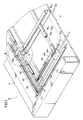
- Fig. 1 is a perspective view showing a portion of a masking device in accordance with the present invention;
- Fig. 2 is an enlarged perspective view of a portion shown by II in Fig. 1;
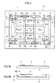
- Fig. 3 is a plan view of an automatic masking device in accordance with the present invention;
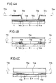
- Figs. 4A to 4C are cross sectional views of the portions shown by IVA-IVA, IVB-IVB and IVC-IVC of Fig. 3;
- Fig. 5 is a perspective view of a conveyor type multiple image printing machine to which the masking device of the present invention can be applied;
- Fig. 6 is a side view of a main portion of the conveyor type multiple image printing machine shown in Fig. 5;
- Figs. 7A and 7B illustrate operation of a nozzle of the conveyor type multiple image printing machine shown in Fig. 5;
- Fig. 8 is a perspective view of a horizontal composer to which the masking device of the present invention can be applied;
- Fig. 9 is a cross sectional view of an original mounting table of the horizontal composer shown in Fig. 8;
- Fig. 10 is a plan view showing a main portion of a conventional masking device; and
- Figs. 11A and 11B are cross sectional views of the portions shown by XIA-XIA and XIB-XIB of Fig. 10.
- A conveyor type multiple image printing machine to which the automatic masking device of the present invention is applied will be briefly described with reference to Figs. 5 and 6.
- The conveyor type multiple image printing machine comprises a printing table 2 which can be elevated and lowered provided on an upper surface of a
body 1; atransparent plate 5 on a lower surface of anedge frame 4; anupper frame 3 which can be opened and closed provided on the printing table 2; amasking device 10 provided on the side of the upper surface of thetransparent plate 5 which will be described later; an originalfilm conveying belt 6 provided movable in the X-Y directions in the figure in relation to the printing table 2; an evacuating apparatus (not shown) for vacuum contact; and alight source 8 for printing. An original film S is positioned by means of the original conveyingbelt 6 in relation to the photosensitive material P such as a PS plate placed on the printing table 2. The image of the original S is formed on the photosensitive material P in this state, and the film S is moved to another position. In this manner, the film S is successively positioned by means of the original conveyingbelt 6, so that a plurality of the images of the original S are printed on the photosensitive material P. - The
upper frame 3 can be moved by anair cylinder 7 to a full open attitude A, a half open attitude B and a closed attitude C, as shown in Fig. 6. Exchange of the photosensitive material P or the original S is carried out in the full open attitude A. The original S is moved in the X-Y directions by the operation of thebelt 6 to be positioned on the photosensitive material P in the half open attitude B. The original S is brought into contact with the photosensitive material P for printing in the closed attitude C. - The original conveying
belt 6 is wound around pulleys arranged in the left and right side of the printing table 2 to surround the printing table 2. The original conveying belt is movable also in the front end rear directions (Y) of the printing table 2. - The original film has a front edge fixed on the original conveying
belt 6 by means of a sticky tape and the film moves in the X-Y directions in relation to the photosensitive material positioned and placed on the printing table 2 to be positioned at a prescribed position of the photosensitive material P. On this occasion, the printing table 2 is a little lowered and air is emitted from anair nozzle 9 so as to prevent the rear end of the original S from being suspended and in contact with the photosensitive material. - This method will be described with reference to Figs. 7A and 7B. In printing, the original S is placed in contact with the photosensitive material P as shown in Fig. 7A. When the original is moved, the printing table 2 is lowered as shown in Fig. 7B. On this occasion, since one end of the original S is fixed on the
positioning belt 6, the other end, which is not fixed, of the original S is suspended as shown by the dotted lines in Fig. 7B. If the suspended original S happens to be in contact with the photosensitive material P, the photosensitive material P may possibly be damaged. Therefore, when the original is to be moved, air is emitted from theair nozzle 9 as shown in Fig. 7B and the original S is horizontally held in the air as shown by the solid line in Fig. 7B. - After the original S is positioned, the
upper frame 3 is closed so that the original is in contact with the photosensitive material P. The maskingdevice 10 is operated to form a desired mask opening. Printing is carried out through the mask opening. - The masking device of the present invention will be described in the following with reference to Figs. 1 to 4C.
- Referring to Fig. 3, the masking
device 10 comprises two pairs ofretractable masking sheets retractable masking sheets 12a·12b are retractably wound aroundrollers edges - The mask driving mechanism comprises a driving
motor 20 through a driving gear;endless transmission belts 23 wound around drivingpulleys 21 and drivenpulleys 22 of a pair ofroll shafts 11·11; and movingblocks 24a·24b for the leading edge fixed on theendless transmission belt 23. By independently driving each of the movingblocks 24a·24b and theroll shafts 11, the mask opening M is defined. An original film S (not shown) is positioned below the mask opening M under thetransparent plate 5. The image of the original film S is printed at a prescribed position of the photosensitive material P by the light transmitted through the mask opening M. - The
leading edges 13a·13b of themasking sheets 12a·12b comprise maskopening defining plates 14a formed of a thin plate arranged close to thetransparent plate 5 for defining the mask opening MX in the left and right directions, and maskingsheet leading plates 15a retractably fixing themasking sheet 12a. The maskingsheet leading plate 15a and the maskopening defining plate 14a are separated into an upper part and a lower part. Maskopening defining plates 14b of the other pair of leadingedges 13b·13b are arranged intersecting the upper part of the maskopening defining plate 14a. - The
masking sheet 12a is rolled up by theshaft 11 by means of a rolling spring, not shown, and a constant tension is applied thereto. The tension is applied only to the maskingsheet leading plate 15a and not to the maskopening defining plate 14a. Therefore, the maskopening defining plate 14a can be made of a relatively thin plate member (for example having the thickness of 0.6 to 0.8 mm). - As shown in Fig. 2, the mask
opening defining plate 14a is supported movable in up and down directions by means of asuspension 26 fixed to the movingblock 24a. When the definingplate 14a is moved, the lower surface thereof is in contact with the upper surface of thetransparent plate 5, and the definingplate 14a is adapted to move along the bend of thetransparent plate 5. Structured in this manner, the maskopening defining plate 14a will not be lift away from the upper surface of thetransparent plate 5. Therefore, there is no possibility of the area in which images are blurred being extended in the periphery of the maskopening defining plate 14a. The movingblock 24a is moved along aguide bar 25. - Meanwhile, a pair of leading
edges 13b·13b defining the mask opening MY in the front end rear directions also comprise maskopening defining plates 14b and maskingsheet leading plates 15b, as shown in Fig. 1. The both are arranged separately in the upper and lower parts. The maskopening defining plate 14b is formed of a thin plate member which is supported movable in the up and down directions by the movingblock 24b. Namely, the tension applied to themasking sheet 12b works on only the maskingsheet leading plate 15b and not the maskopening defining plate 14b. - Therefore, as shown in Figs. 4A and 4B, the leading
edges 13b (including 14b and 15b) defining the opening portion MY in the front and rear direction is arranged close to the maskopening defining plate 14a which is formed of a thin plate member (having the thickness of about 0.6 to 0.8 mm) defining the opening portion MX in the left and right directions arranged in contact with thetransparent plate 5. - Namely, the thickness of the mask
opening defining plate 14b in the left and right directions which influences the size of the area in which images are blurred in the periphery of the area EY to be exposed in the front and rear directions is made about 1/4 to 1/5 of a conventional one (about 3.2 mm, see 112b + 113b in Fig. 11B). Consequently, as shown in Fig. 4B, there remains little possibility of the area in which images are blurred extending near the periphery of the area EY to be exposed in the front and rear directions. - The above described pair of leading
edges 13b·13b may be formed integrally by a thick plate member and they need not be separated into the maskopening defining plate 14b and the maskingsheet leading plate 15b. In that case, the edge side (mask opening defining portion) defining the mask opening MY may be arranged near and upper the maskopening defining plate 14a which is separately arranged as described above (see Fig. 4C). - When the pair of leading
edges 13b·13b are separated into the maskopening defining plate 14b and the maskingsheet leading plate 15b, only the maskopening defining plate 14b may be arranged between the maskopening defining plate 14a and the maskingsheet leading plate 15a of the other pair of leadingedges 13a·13a and the maskingsheet leading plate 15b may be arranged above the other maskingsheet leading plate 15a. - The present invention is especially advantageous when applied to a masking device which requires large light shading area. The reason for this is that even when the rolling up force applied to the masking sheet is large, the mask opening defining plate can be formed of a thin plate member.
- Although a conveyor type multiple image printing machine has been described in the above embodiment, the present invention can be applied not only to machines of this type but also to original holders of a general horizontal composer (vertical composer) and the like.
- Referring to Figs. 8 and 9, an example of the present invention applied to a horizontal composer will be described. Referring to Fig. 8, a horizontal composer to which the masking device for the present invention is applied comprises a printing table 36 holding a photosensitive material P and an original table 32 provided relatively movable in parallel to the surface of the photosensitive material P on the printing table 36. The original table 32 moves in the Y direction, as shown, on a Y axis table 33, and the Y axis table 33 moves in the X direction, as shown, on the printing table 36, whereby the original table 32 is moved to an arbitrary position on the photosensitive material P in parallel to the surface of the photosensitive material P. The original table 32 comprises a
printing light source 8 provided above and a transparent plate (not shown) holding an original film at the bottom portion thereof. In this horizontal composer, the automatic masking device is also provided on the transparent plate. The structure of the automatic masking device is the same as that applied to the above described conveyor type multiple image printing machine, so that the description thereof is not repeated. - Referring to Fig. 9, the positional relation between the original table 32 and the
automatic masking device 10 will be described. The original table 32 comprises theautomatic masking device 10 and a transparent plate (that is, an original holder) 5 provided therebelow. Theautomatic masking device 10 is moved upward and downward together with thetransparent plate 5 by means of an elevating apparatus, not shown, in the original table 32. Therefore, the original film S can be brought into contact with the photosensitive material P held on the lower surface of thetransparent plate 5. Generally, the original film S is attracted and held by a vacuum groove provided on the periphery of the lower surface of thetransparent plate 5. - The masking device of the present invention applied to a vertical composer will be described in the following. In the vertical composer, a biasing spring should be preferably be provided so that the mask
opening defining plates transparent plate 5 of the original holder. - The reason for this is as follows. The masking
device 10 is arranged horizontally as shown in Fig. 3 in a horizontal composer, so that theopening defining plate 14a comes into contact with thetransparent plate 5 by the weight of the definingplate 14a itself. However, in a vertical composer, the automatic masking device is arranged vertically. Since thetransparent plate 5 is arranged erected vertically, theopening defining plate 14a does not come into contact with thetransparent plate 5 by the weight of itself. Therefore, a biasing spring should be provided which forces the defining operate 14a to thetransparent plate 5 to be in contact therewith. - Although a multiple image printing composer such as conveyor type multiple image printing machine has been described in the above embodiments, it goes without saying that the present invention can be applied to a so-called composer camera in which at least one original is taken on one photosensitive material.
- As is apparent from the foregoing, at least a pair of leading edges comprise a mask opening defining plate and a masking sheet leading plate and the two plates are arranged separately such that the tension of the masking sheet does not work on the mask opening defining plate. Accordingly, the mask opening defining plate arranged adjacent to transparent plate can be made thin. Therefore, even when the mask opening defining portion of the other pair of leading edges is arranged adjacent to and intersecting with the upper side of the mask opening defining plate, the area in which images are blurred near the periphery of the area to be exposed caused by the other pair of the mask opening defining portions will not be so large as in the prior art.
- Although the present invention has been described and illustrated in detail, it is clearly understood that the same is by way of illustration and example only and is not to be taken by way of limitation, the scope of the present invention being limited only by the terms of the appended claims.
Claims (4)
- A masking device (10) for covering during projection of an original image (S) on a photosensitive material (PS) that area of said photosensitive material (PS) which is not to be exposed, the masking device (10) comprising:
a light transmitting plate (5) having a pair of edge portions extending in a first direction (y) and a pair of edge portions extending in a second direction (x) intersecting said first direction (y);
a pair of first elongate bars (15a) extending in said first direction (y) and a pair of second elongate bars (15b) extending in said second direction (x), said two pairs of intersecting bars (15a,15b) defining a mask opening (Mx,My) in correspondence with a portion of said light transmitting plate (5), each one of said bars (15a,15b) being supported for movement transversal to their direction of extension in order to adjust the dimensions of said mask opening (Mx,My),
each one of said bars (15a,15b) being provided with a respective flexible sheet (12) having one end attached thereto and an opposite second end fixed adjacent to a respective one of said edge portions of said light transmitting plate (5) in order to cover that region of said plate which is comprised between said edge portion and said bar,
said masking device (10) being characterised in that each of said first bars (15a) is connected to a respective elongate first thin plate (14a) extending parallel to said first bar and facing said light transmitting plate (5), said first thin plate (14a) constituting the edge of said mask opening at the side of said first bar and said first bar being spaced from said thin plate in a direction perpendicular to said light transmitting plate (5), and in that
said second bars (15b) extend through the spaces between each of said first bars and the respective thin plate (14a). - A masking device according to Claim 1, further characterised in that each of said second bars (15b) is connected to a respective elongate second thin plate (14b) extending parallel to said second bar and constituting the edge of said mask opening at the side of said second bar, said second thin plate (14b) being located between said light transmitting plate (5) and said first thin plates (14a).
- A masking device according to Claim 1, further comprising a pair of guided movement means (23,25) provided on both opposite sides of said light transmitting plate (5) and extending in said second direction (x), said first bars (15a) being movable along said guiding means.
- A masking device according to Claim 1, further comprising a roller (11a, 11b) provided at each one of said end regions of said light transmitting plate (5) for yieldably and retractably winding thereon a portion of a respective one of said cover sheets (12a,12b).
Applications Claiming Priority (2)
| Application Number | Priority Date | Filing Date | Title |
|---|---|---|---|
| JP63260295A JPH02106754A (en) | 1988-10-14 | 1988-10-14 | Automatic mask device |
| JP260295/88 | 1988-10-14 |
Publications (3)
| Publication Number | Publication Date |
|---|---|
| EP0363981A2 EP0363981A2 (en) | 1990-04-18 |
| EP0363981A3 EP0363981A3 (en) | 1991-09-04 |
| EP0363981B1 true EP0363981B1 (en) | 1995-07-19 |
Family
ID=17346061
Family Applications (1)
| Application Number | Title | Priority Date | Filing Date |
|---|---|---|---|
| EP89119068A Expired - Lifetime EP0363981B1 (en) | 1988-10-14 | 1989-10-13 | Automatic masking device |
Country Status (4)
| Country | Link |
|---|---|
| US (1) | US5005044A (en) |
| EP (1) | EP0363981B1 (en) |
| JP (1) | JPH02106754A (en) |
| DE (1) | DE68923522T2 (en) |
Families Citing this family (5)
| Publication number | Priority date | Publication date | Assignee | Title |
|---|---|---|---|---|
| US5130746A (en) * | 1991-02-20 | 1992-07-14 | Ray Hicks | Photographic printer mask mechanism |
| DE4116436A1 (en) * | 1991-05-18 | 1992-11-19 | Krause Biagosch Gmbh | Printing-plate illumination equipment outside working area - has extensible mask between adjustable holders and slewing in relation to table |
| EP0539334A3 (en) * | 1991-10-22 | 1993-07-28 | Luescher Ag Maschinenbau | Masking method for the production of printing plates and masking foil for implementing such a method |
| DE4141758C2 (en) * | 1991-12-18 | 1997-07-17 | Kaiser Fototechnik Gmbh & Co K | Magnification frame |
| JP2970312B2 (en) * | 1993-06-03 | 1999-11-02 | ノーリツ鋼機株式会社 | Paper mask size switching method and paper mask device |
Family Cites Families (4)
| Publication number | Priority date | Publication date | Assignee | Title |
|---|---|---|---|---|
| DE3402345A1 (en) * | 1983-01-25 | 1984-08-09 | Fuji Photo Film Co., Ltd., Minami Ashigara, Kanagawa | COPYING TABLE FOR A REPRODUCTION CAMERA |
| JPS60140960A (en) * | 1983-12-28 | 1985-07-25 | Canon Inc | Data transmission system |
| JPS60140960U (en) * | 1984-02-28 | 1985-09-18 | 株式会社 ヤマトヤ商会 | Automatic mask device for multi-sided printing machine |
| DE3430535C2 (en) * | 1984-08-18 | 1986-08-21 | Krause Biagosch GmbH, 4800 Bielefeld | Device for forming a mask |
-
1988
- 1988-10-14 JP JP63260295A patent/JPH02106754A/en active Granted
-
1989
- 1989-09-21 US US07/410,201 patent/US5005044A/en not_active Expired - Fee Related
- 1989-10-13 EP EP89119068A patent/EP0363981B1/en not_active Expired - Lifetime
- 1989-10-13 DE DE68923522T patent/DE68923522T2/en not_active Expired - Fee Related
Also Published As
| Publication number | Publication date |
|---|---|
| DE68923522D1 (en) | 1995-08-24 |
| EP0363981A3 (en) | 1991-09-04 |
| JPH02106754A (en) | 1990-04-18 |
| JPH0545950B2 (en) | 1993-07-12 |
| US5005044A (en) | 1991-04-02 |
| DE68923522T2 (en) | 1996-01-04 |
| EP0363981A2 (en) | 1990-04-18 |
Similar Documents
| Publication | Publication Date | Title |
|---|---|---|
| US6904844B2 (en) | Printing plate removing/supplying device | |
| EP0363981B1 (en) | Automatic masking device | |
| US4565443A (en) | Printing apparatus | |
| US4655583A (en) | Apparatus for transporting a web of photosensitive material in a photo printer | |
| EP0628855B1 (en) | Exposure stage device | |
| US6530322B1 (en) | Suction transport device of a printing plate | |
| JP2006301170A (en) | Exposing device and method therefor | |
| GB1578099A (en) | Film transport means for a contact printing machine | |
| CA1104598A (en) | Sheet feed | |
| US4316669A (en) | Exposure apparatus | |
| JPS6398645A (en) | Positioning and holding device for photosensitive material | |
| EP0867758B1 (en) | Image recording apparatus and a light-sensitive material distributing device for use therein | |
| US4204736A (en) | Method and device for contact-printing | |
| EP0854387B1 (en) | Photo-processing apparatus | |
| US6964228B2 (en) | Conveying device | |
| US4592652A (en) | Sheet material contacting device | |
| US5993083A (en) | Method and device for distributing sheets of light-sensitive material | |
| US4764794A (en) | Original film discharge mechanism in an inclined-type exposing apparatus | |
| CA2091314C (en) | Guide apparatus | |
| US4580892A (en) | Contact printing apparatus | |
| US5629754A (en) | Photographic printing apparatus and a roll magazine holder therefor | |
| JPH0147779B2 (en) | ||
| JP3785252B2 (en) | Photosensitive material distribution method | |
| JP3785251B2 (en) | Photosensitive material sorting device | |
| JP3657746B2 (en) | Sorting device |
Legal Events
| Date | Code | Title | Description |
|---|---|---|---|
| PUAI | Public reference made under article 153(3) epc to a published international application that has entered the european phase |
Free format text: ORIGINAL CODE: 0009012 |
|
| AK | Designated contracting states |
Kind code of ref document: A2 Designated state(s): DE FR GB |
|
| PUAL | Search report despatched |
Free format text: ORIGINAL CODE: 0009013 |
|
| AK | Designated contracting states |
Kind code of ref document: A3 Designated state(s): DE FR GB |
|
| 17P | Request for examination filed |
Effective date: 19920123 |
|
| 17Q | First examination report despatched |
Effective date: 19940616 |
|
| GRAA | (expected) grant |
Free format text: ORIGINAL CODE: 0009210 |
|
| AK | Designated contracting states |
Kind code of ref document: B1 Designated state(s): DE FR GB |
|
| ET | Fr: translation filed | ||
| REF | Corresponds to: |
Ref document number: 68923522 Country of ref document: DE Date of ref document: 19950824 |
|
| PLBE | No opposition filed within time limit |
Free format text: ORIGINAL CODE: 0009261 |
|
| STAA | Information on the status of an ep patent application or granted ep patent |
Free format text: STATUS: NO OPPOSITION FILED WITHIN TIME LIMIT |
|
| 26N | No opposition filed | ||
| PGFP | Annual fee paid to national office [announced via postgrant information from national office to epo] |
Ref country code: GB Payment date: 19971006 Year of fee payment: 9 |
|
| PGFP | Annual fee paid to national office [announced via postgrant information from national office to epo] |
Ref country code: FR Payment date: 19971009 Year of fee payment: 9 |
|
| PGFP | Annual fee paid to national office [announced via postgrant information from national office to epo] |
Ref country code: DE Payment date: 19971017 Year of fee payment: 9 |
|
| PG25 | Lapsed in a contracting state [announced via postgrant information from national office to epo] |
Ref country code: GB Free format text: LAPSE BECAUSE OF NON-PAYMENT OF DUE FEES Effective date: 19981013 |
|
| GBPC | Gb: european patent ceased through non-payment of renewal fee |
Effective date: 19981013 |
|
| PG25 | Lapsed in a contracting state [announced via postgrant information from national office to epo] |
Ref country code: FR Free format text: LAPSE BECAUSE OF NON-PAYMENT OF DUE FEES Effective date: 19990630 |
|
| REG | Reference to a national code |
Ref country code: FR Ref legal event code: ST |
|
| PG25 | Lapsed in a contracting state [announced via postgrant information from national office to epo] |
Ref country code: DE Free format text: LAPSE BECAUSE OF NON-PAYMENT OF DUE FEES Effective date: 19990803 |