EP0363396B1 - Procede et dispositif pour determiner la position d'un vehicule routier - Google Patents
Procede et dispositif pour determiner la position d'un vehicule routier Download PDFInfo
- Publication number
- EP0363396B1 EP0363396B1 EP19880904498 EP88904498A EP0363396B1 EP 0363396 B1 EP0363396 B1 EP 0363396B1 EP 19880904498 EP19880904498 EP 19880904498 EP 88904498 A EP88904498 A EP 88904498A EP 0363396 B1 EP0363396 B1 EP 0363396B1
- Authority
- EP
- European Patent Office
- Prior art keywords
- road
- road network
- driving data
- roads
- calculated
- Prior art date
- Legal status (The legal status is an assumption and is not a legal conclusion. Google has not performed a legal analysis and makes no representation as to the accuracy of the status listed.)
- Expired - Lifetime
Links
Images

Classifications
-
- G—PHYSICS
- G01—MEASURING; TESTING
- G01C—MEASURING DISTANCES, LEVELS OR BEARINGS; SURVEYING; NAVIGATION; GYROSCOPIC INSTRUMENTS; PHOTOGRAMMETRY OR VIDEOGRAMMETRY
- G01C21/00—Navigation; Navigational instruments not provided for in groups G01C1/00 - G01C19/00
- G01C21/26—Navigation; Navigational instruments not provided for in groups G01C1/00 - G01C19/00 specially adapted for navigation in a road network
- G01C21/28—Navigation; Navigational instruments not provided for in groups G01C1/00 - G01C19/00 specially adapted for navigation in a road network with correlation of data from several navigational instruments
- G01C21/30—Map- or contour-matching
-
- G—PHYSICS
- G08—SIGNALLING
- G08G—TRAFFIC CONTROL SYSTEMS
- G08G1/00—Traffic control systems for road vehicles
- G08G1/123—Traffic control systems for road vehicles indicating the position of vehicles, e.g. scheduled vehicles; Managing passenger vehicles circulating according to a fixed timetable, e.g. buses, trains, trams
- G08G1/133—Traffic control systems for road vehicles indicating the position of vehicles, e.g. scheduled vehicles; Managing passenger vehicles circulating according to a fixed timetable, e.g. buses, trains, trams within the vehicle ; Indicators inside the vehicles or at stops
- G08G1/137—Traffic control systems for road vehicles indicating the position of vehicles, e.g. scheduled vehicles; Managing passenger vehicles circulating according to a fixed timetable, e.g. buses, trains, trams within the vehicle ; Indicators inside the vehicles or at stops the indicator being in the form of a map
Definitions
- the invention relates to a method for determining the position of a land vehicle according to the preamble of claim 1.
- EVA electronic traffic controller for motorists
- Methods and devices for determining the position of land vehicles that only contain driving data such as Detecting and evaluating distances and direction of travel by means of coupling location, suffer a loss of location after a long journey, which can lead to an incorrect recommendation.
- This loss of location can be kept within such limits by repeated correction in the form of a comparison with data from a stored, digitized road network that the reliability of the recommendation is not impaired.
- problems can occur when performing the comparison, e.g. are due to the density of the road network, the limited storage space of the computer arrangement in the vehicle or the computing time required by the computer.
- the location inaccuracy may have increased so much that the position determined from the driving data can be assigned to the road network, but this deviates from the actual position and the comparison is then made to an incorrect street.
- a restriction to a thinned-out road network is not desirable, since the system requires that recommendations can be made between any start and finish positions.
- the area of the order of magnitude of a federal state or the entire national territory of the Federal Republic of Germany must be taken into account.
- FR-A-2 179 709 shows a monitoring system for vehicles, where a map has a close-meshed grid and the grid is chosen so small that only one piece of road can lie in each mesh. If such a stretch of road lies in the mesh, this mesh is defined with a logical 1.
- the invention is characterized in claim 1 (method) and in claim 8 (device).
- the entire road network does not have to be used for the location determination. Rather, the digitized road network is divided into meshes, with several meshes in each mesh. The vehicle position is now determined by means of dead reckoning and by comparison with the digitized road network of this mesh and the adjacent meshes.
- the invention is based on the consideration that a loss of location in the evaluation of driving data increases only gradually with increasing distance and therefore with corrections following one after the other can be kept within limits. As a result, only the streets near the calculated position play a role in the comparison. Since the relevant roads change constantly when driving through the road network, a criterion is required as to which roads should be used for the comparison.
- the invention creates this criterion by spanning the digitized road network with a grid, so that the road network is now broken down into meshes and it can be clearly defined whether roads lie within the relevant area or not.
- the relevant area is not limited by a single stitch. Rather, the mesh within which the position calculated from the driving data lies is made the middle field of a larger area in which the roads are also used for comparison. Therefore, it does not lead to errors if the actual position is not in the defined stitch but in an adjacent stitch.
- the amount of data required for the adjustment is kept approximately constant and at a relatively low level, so that the adjustment can be carried out in a sufficiently short time .
- the streets to which the calculated position is finally compared are selected based on the most likely street.
- the relevant streets that is to say the streets in the vicinity of the mesh in which the calculated position is located, are weighted differently.
- the weighting can e.g. proximity, directional match, or a combination of both.
- the weighting can then begin again, so that this also limits the amount of data to be processed and a sufficiently high computing speed can be obtained.
- a particularly user-friendly advantage of the method is that due to the self-correction, the digital road network only has to contain the roads approved for public transport. Short, non-public streets, e.g. courtyard entrances, passages, petrol station entrances or parking lots do not need to be recorded. Rather, the method is able to assign the position of the vehicle to this road again after returning to one of the roads stored in the digitized road network. An exact entry of the starting point is also not necessary, so that this can be carried out very roughly and can also be carried out in the garage or on a parking space that is not stored in the digitized road network.
- the invention has for its object to provide a method and a device, which enables a reliable and quick comparison of the position calculated from the driving data with the road network even with extensive detailed digitized road networks.
- the first memory of the device comprises the digitized road network
- a grid is stored in the second memory, with which the road network is covered.
- the computer thus receives a road network broken down into a large number of meshes and can make a selection from the entire road network as to which roads should be used to compare the position obtained from the driving data with the digitized road network.
- the scope of the data to be taken into account can thus be limited and the position determination and correction can be carried out in a sufficiently short time.
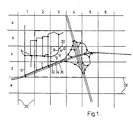
- the roads are shown as graphs, the nodes of which intersections k and the edges of which the road sections g between two intersections.
- the edges are composed of straight pieces g such that deviations of the graph from the actual course of the road do not exceed certain limit values, for example 10 meters, 15 °.
- the graph is spanned with a grid of vertical lines 26 and horizontal lines 28.
- the step size of the grid that is to say the distance between two grid lines 26 or 28, depends on the road density, or expressed in graph theory, on the edge density.
- Road density is the number of roads per unit area.
- the step size can vary between 125 meters in the inner city area and approx. 1000 meters in the local network. It is preferably chosen for each area so that the number of streets touching a mesh does not significantly exceed 10.
- the stitch with the coordinates c number 3 contains a list of the streets 30, 32, 34 and 36.
- the stitch with the coordinates d number 3 contains only the streets 32, 34 and 36.
- the roads relevant for the comparison are not only determined by the mesh within which the current position of the vehicle is located, in FIG. 1 it is the starting point S in the mesh with the coordinates c number 3, rather the in streets surrounding the selected mesh.
- the environment is formed here by those meshes which adjoin the mesh in which the current position is located. So there are eight more stitches with the coordinates b2, b3, b4, c2, c4, d2, d3 and d4.
- the area is graphically highlighted by a dash-dotted frame.
- the procedure for determining the position is essentially as follows. First a start position is entered and the stitch within which the start position lies is determined. The current position is then calculated from this starting position. The driving data transmitted by a driving data generator, from which a current position is determined, are used for this purpose. However, this instantaneous position deviates from the actual position with increasing travel distance. So there is a location error.
- the current position is compared at predetermined intervals with the stored road network and corrected to a position that is on one of the roads.
- the roads used for the comparison are in the immediate vicinity of the current position. These are preferably the streets which are located within the stitch in which the current position lies and the streets which are located in the stitches surrounding the aforementioned stitch.
- the relevant roads are weighted according to the probability with which the calculated current position can lie on them.
- the road with the highest weighting is finally selected, the current position is corrected so that it comes to rest on the road and this new position is now used as an exit for the further position determination.
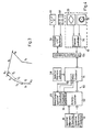
- an initialization takes place in 40. This is understood to mean the initial entry of the start position. Since there is still no location error in this phase, the further procedure can be initiated by deleting or resetting the evaluation memories for the weighting of the roads. This happens in 42.
- a position calculation is carried out from driving data at short intervals, maximum 10 meters. This is done in 44. The position calculation is preferably based on the principle of coupling location, in which both the distance traveled and the direction of travel are taken into account. In addition, a direction determination using a compass can also be used.
- the previous stitch is the one in which the starting position lies. With each further run, reference is always made to the previous instantaneous position.
- the streets are then weighted in 48 according to the probability that the current position could be on one of them.
- the weighting can be done, for example, in such a way that the distance between the calculated current position is compared with the individual streets and the streets are assigned graded numbers according to the distance.
- the street with the smallest distance receives the highest, the one with the greatest distance the smallest rating number.
- the same then takes place between the direction of travel and the direction of the roads.
- the street whose direction most closely matches the direction of travel receives the highest rating, the one that corresponds the least with the direction of travel receives the lowest rating.
- the evaluations between distance and direction can also be combined.
- w is the weighting or evaluation
- ⁇ g the direction of a straight section of the road
- ⁇ f the direction of travel
- a the distance between the calculated position and the road.
- the weights of the streets After the weights of the streets have been calculated in 48, they are added to an evaluation memory. This contains memory locations for the weightings of each of the relevant streets. The weightings are added up for each new calculation. After the calculation, a decision is made in 50 as to whether a threshold value has been reached. If this is the case, the calculated position in the road with the highest weighting is corrected in 52. Then the process flow continued at 42.
- the process sequence is continued with 44. If the calculated instantaneous position is not in the previous mesh, the program branches from 46 to 54 and the list of relevant roads to be weighted is updated. The newly added streets are weighted for the first time, the weightings of the streets that are no longer taken into account are deleted and the weightings of the streets that are still taken into account are adopted. The method step in FIG. 48 then continues.
- a vehicle should drive from the intersection k1 to the intersection k2.
- the straight sections g1, g2 and g3 are traversed.
- the position determination on the basis of the driving data which is said to have errors, results in a virtual driving route from the straight lines g1 ′, g2 ′ and g3 ′.
- the instantaneous position is calculated and the roads g1-g6 taken into account are weighted.
- the weighting is just after. performed the distance or only in the direction, for example, the line segment g4 because of the small distance or the line segments g5 and g6 because of the matching direction could be given high weightings.
- the combination of both criteria means that after passing through the virtual line segment g3 ', the end of line g3 appears as the most likely position and the current position is thus corrected to this position.
- FIG. 4 finally shows a block diagram of the device according to the invention.
- This includes a computer 14, to which driving data from a driving data transmitter 10 are fed via an input-output interface 56, as well as a first memory 12 for a digitized road network and a second memory 16 for a grid network.
- a memory 58 for the operating software and a read / write memory arrangement 60 are also connected to the computer 14.
- the read-write memory arrangement 60 comprises a working memory 62, a third memory 22 for an evaluation or weighting of the roads and a fourth memory 24 for a threshold value.
- the computer Via the input-output interface 56, the computer is also equipped with a Display and operating part 64 connected, which has a display 66 and an input keyboard 68.
- the driving data transmitter 10 comprises in detail a sensor controller 70 as well as wheel sensors 18 and a compass 20.
- the starting position is first entered into the computer 14 via the input keyboard 68.
- the driving data generator 10 delivers driving data at predetermined intervals while driving, which originate from the wheel sensors 18 and possibly from the compass 20 and are evaluated in the computer 14 according to the coupling location principle.
- the current position is calculated from the driving data.
- the road network stored in the first memory and the grid network stored in the second memory are then transferred in sections to the working memory until the stitch within which the current position lies is found.
- This stitch, the stitches adjacent to that stitch, and the streets within that area are then copied to the memory 62.
- a weighting of the relevant, ie in the mesh, in which the current position is lies, and made in the adjacent meshes streets as well as the streets touching the meshes is transferred separately to the third store 22 for each street and added to the values already present there.
- a comparison is made between the weights and a threshold value stored in the fourth memory 24. This takes place in a comparator, wherein the comparator can be present discretely or can be implemented by appropriate control of the computer 14. If the threshold value is reached or exceeded, the computer 14 compares the current position with the position of the road with the highest weighting and deletes the third memory 22.
- the process then begins again until the threshold value of one of the values determining the weighting of the roads is exceeded again. In this way, a loss of location that has occurred in the meantime is always eliminated.
- the computer determines that the vehicle is approaching an intersection or junction at which the direction of travel has to be changed, it makes a corresponding recommendation on the display 66. These recommendations are given until the target position is reached or until a new target position is entered.
Landscapes
- Engineering & Computer Science (AREA)
- Radar, Positioning & Navigation (AREA)
- Remote Sensing (AREA)
- Physics & Mathematics (AREA)
- General Physics & Mathematics (AREA)
- Automation & Control Theory (AREA)
- Navigation (AREA)
- Traffic Control Systems (AREA)
Abstract
Claims (11)
Applications Claiming Priority (2)
| Application Number | Priority Date | Filing Date | Title |
|---|---|---|---|
| DE19873718996 DE3718996A1 (de) | 1987-06-06 | 1987-06-06 | Verfahren und vorrichtung zur positionsbestimmung eines landfahrzeugs |
| DE3718996 | 1987-06-06 |
Publications (2)
| Publication Number | Publication Date |
|---|---|
| EP0363396A1 EP0363396A1 (fr) | 1990-04-18 |
| EP0363396B1 true EP0363396B1 (fr) | 1991-11-21 |
Family
ID=6329199
Family Applications (1)
| Application Number | Title | Priority Date | Filing Date |
|---|---|---|---|
| EP19880904498 Expired - Lifetime EP0363396B1 (fr) | 1987-06-06 | 1988-06-04 | Procede et dispositif pour determiner la position d'un vehicule routier |
Country Status (4)
| Country | Link |
|---|---|
| US (1) | US5023798A (fr) |
| EP (1) | EP0363396B1 (fr) |
| DE (2) | DE3718996A1 (fr) |
| WO (1) | WO1988009916A1 (fr) |
Families Citing this family (31)
| Publication number | Priority date | Publication date | Assignee | Title |
|---|---|---|---|---|
| DE4009355A1 (de) * | 1990-03-23 | 1991-09-26 | Teves Gmbh Alfred | Schaltungsanordnung fuer ein kraftfahrzeug mit blockierschutz- und/oder antriebsschlupfregelung |
| DE4028214C2 (de) * | 1990-09-06 | 1996-05-30 | Nuclear Cargo & Service Gmbh | Verfahren zur Umsetzung von in Werten eines geographischen Koordinatensystems erzeugten Standortdaten in eine auf einem karthesischen Koordinatensystem beruhende Rasterform |
| US5184303A (en) * | 1991-02-28 | 1993-02-02 | Motorola, Inc. | Vehicle route planning system |
| US5515284A (en) * | 1991-09-25 | 1996-05-07 | Zexel Corporation | Storage medium for map information for navigation system and system for offering map information for navigation system |
| US5283575A (en) * | 1991-11-08 | 1994-02-01 | Zexel Corporation | System and method for locating a travelling vehicle |
| JP2584564B2 (ja) * | 1992-04-15 | 1997-02-26 | 住友電気工業株式会社 | 車両位置検出装置 |
| JP3221746B2 (ja) * | 1992-10-14 | 2001-10-22 | パイオニア株式会社 | ナビゲーション装置 |
| WO1995014910A1 (fr) * | 1993-11-26 | 1995-06-01 | Mannesmann Ag | Procede de realisation d'une carte routiere numerisee |
| JP3322754B2 (ja) * | 1994-05-17 | 2002-09-09 | 富士通株式会社 | 並列計算機 |
| US5512904A (en) * | 1994-06-13 | 1996-04-30 | Andrew Corporation | Method and apparatus of establishing a vehicle azimuth |
| WO1996024216A1 (fr) | 1995-01-31 | 1996-08-08 | Transcenic, Inc. | Photographie referencee dans l'espace |
| US5862511A (en) * | 1995-12-28 | 1999-01-19 | Magellan Dis, Inc. | Vehicle navigation system and method |
| US5991692A (en) * | 1995-12-28 | 1999-11-23 | Magellan Dis, Inc. | Zero motion detection system for improved vehicle navigation system |
| US6029111A (en) * | 1995-12-28 | 2000-02-22 | Magellan Dis, Inc. | Vehicle navigation system and method using GPS velocities |
| DE19623666C1 (de) * | 1996-06-13 | 1997-11-20 | Siemens Ag | Verfahren zur dynamischen Routenempfehlung |
| CA2265994C (fr) | 1996-09-16 | 2007-03-27 | Minorplanet Limited | Surveillance des positions de vehicules |
| US6308134B1 (en) | 1996-12-27 | 2001-10-23 | Magellan Dis, Inc. | Vehicle navigation system and method using multiple axes accelerometer |
| EP0944032A4 (fr) * | 1997-07-02 | 2001-02-28 | Mitsubishi Electric Corp | Navigateur pour vehicule |
| DE19835051A1 (de) * | 1998-08-04 | 2000-02-10 | Bosch Gmbh Robert | Einrichtung zur Codierung und zur Decodierung von Orten |
| US6374184B1 (en) * | 1999-09-10 | 2002-04-16 | Ge-Harris Railway Electronics, Llc | Methods and apparatus for determining that a train has changed paths |
| DE10114412C5 (de) * | 2001-03-23 | 2006-07-06 | Audi Ag | Verfahren zur Erzeugung einer Straßennetzkarte sowie Verfahren und Vorrichtung zur Steuerung von Fahrzeugsystemen in einem Fahrzeug |
| US7046827B2 (en) * | 2002-02-15 | 2006-05-16 | International Business Machines Corporation | Adapting point geometry for storing address density |
| AT414280B (de) * | 2002-09-12 | 2006-11-15 | Siemens Ag Oesterreich | Verfahren zur identifikation eines mautpflichtigen strassenabschnittes |
| JP4071643B2 (ja) * | 2003-01-22 | 2008-04-02 | インクリメント・ピー株式会社 | 案内誘導装置、そのシステム、その方法、そのプログラム、および、そのプログラムを記録した記録媒体 |
| GB2403008A (en) * | 2003-06-18 | 2004-12-22 | Infomatiq Ltd | A method of locating and aiding a pedestrian |
| JP4493953B2 (ja) * | 2003-08-22 | 2010-06-30 | 富士通テン株式会社 | 移動体位置提供装置および移動体位置提供システム |
| US7912630B2 (en) * | 2004-12-14 | 2011-03-22 | International Business Machines Corporation | Method and system for performing programmatic actions based upon vehicle approximate locations |
| US7212916B2 (en) * | 2004-12-14 | 2007-05-01 | International Business Machines Corporation | Obtaining contextual vehicle information |
| US20060195261A1 (en) * | 2005-02-10 | 2006-08-31 | Homeland Integrated Security Systems, Inc. | Electronic device for tracking and monitoring assets |
| CN102713521B (zh) * | 2009-10-22 | 2015-07-15 | 通腾德国股份有限公司 | 用gps踪迹产生、细化及扩充增量地图 |
| CN108364456B (zh) * | 2018-01-12 | 2021-03-09 | 山东高速信息工程有限公司 | 一种确定高速公路桩号的方法、存储介质、装置及系统 |
Family Cites Families (7)
| Publication number | Priority date | Publication date | Assignee | Title |
|---|---|---|---|---|
| US3789198A (en) * | 1972-04-10 | 1974-01-29 | Boeing Co | Vehicle location monitoring system |
| GB1470694A (en) * | 1974-06-08 | 1977-04-21 | Marconi Co Ltd | Vehicle location systems |
| GB2139794A (en) * | 1983-05-09 | 1984-11-14 | Hubert Ralph Waldo Rabson | Comprehensive road direction indicators |
| US4796191A (en) * | 1984-06-07 | 1989-01-03 | Etak, Inc. | Vehicle navigational system and method |
| JPS61250671A (ja) * | 1985-04-27 | 1986-11-07 | 株式会社デンソー | 地図表示装置 |
| US4924402A (en) * | 1986-07-02 | 1990-05-08 | Pioneer Electronic Corporation | Method for identifying current position of vehicle |
| DE3828725A1 (de) * | 1987-09-29 | 1989-04-13 | Pioneer Electronic Corp | Verfahren zum aufzeichnen der fahrtroutendaten fuer eine navigationsvorrichtung eines kraftfahrzeuges |
-
1987
- 1987-06-06 DE DE19873718996 patent/DE3718996A1/de not_active Withdrawn
-
1988
- 1988-06-04 EP EP19880904498 patent/EP0363396B1/fr not_active Expired - Lifetime
- 1988-06-04 WO PCT/DE1988/000332 patent/WO1988009916A1/fr not_active Ceased
- 1988-06-04 US US07/457,760 patent/US5023798A/en not_active Expired - Lifetime
- 1988-06-04 DE DE8888904498T patent/DE3866356D1/de not_active Expired - Lifetime
Also Published As
| Publication number | Publication date |
|---|---|
| US5023798A (en) | 1991-06-11 |
| WO1988009916A1 (fr) | 1988-12-15 |
| EP0363396A1 (fr) | 1990-04-18 |
| DE3718996A1 (de) | 1988-12-22 |
| DE3866356D1 (de) | 1992-01-02 |
Similar Documents
| Publication | Publication Date | Title |
|---|---|---|
| EP0363396B1 (fr) | Procede et dispositif pour determiner la position d'un vehicule routier | |
| EP3491417B1 (fr) | Procédé et système de détection de points de repère dans un environnement de circulation d'une unité mobile | |
| DE3908702C2 (fr) | ||
| DE10356695B4 (de) | Navigationssystem | |
| DE102013208521A1 (de) | Kollektives Erlernen eines hochgenauen Straßenmodells | |
| EP3375683A1 (fr) | Procédé de prédiction d'une information topographique | |
| EP2020589A2 (fr) | Procédé d'affichage schématique d'une manoeuvre dans un système de navigation | |
| DE102016213782A1 (de) | Verfahren, Vorrichtung und computerlesbares Speichermedium mit Instruktionen zur Bestimmung der lateralen Position eines Fahrzeuges relativ zu den Fahrstreifen einer Fahrbahn | |
| EP0861482A2 (fr) | Procede et unite pour le guidage fiable d'un vehicule | |
| DE102010007091A1 (de) | Verfahren zur Positionsermittlung für ein Kraftfahrzeug | |
| EP4176424B1 (fr) | Attribution de feux de signalisation à une voie à partir de données d'essaim | |
| DE102016214028A1 (de) | Verfahren und System zum Bestimmen einer Position einer mobilen Einheit | |
| WO2011067169A1 (fr) | Procédé pour simplifier une description d'un itinéraire routier | |
| DE102015000399A1 (de) | Kartographieren von Fahrspuren mittels Fahrzeugflottendaten | |
| DE102014212866A1 (de) | Verfahren zum Ermitteln eines Parkplatzes aus einer Anzahl von Messpunkten | |
| DE102017218779A1 (de) | Vorrichtung und Verfahren zur Bewertung und/oder Planung einer Route sowie Fahrzeug | |
| EP3990863A1 (fr) | Équilibrage des systèmes de coordonnées de plusieurs cartes basés sur des trajectoires | |
| DE102014212336A1 (de) | Verfahren zum Verarbeiten von Messdaten eines Fahrzeuges zur Bestimmung des Beginns einer Parkplatzsuche und Computerprogrammprodukt | |
| WO2006128601A1 (fr) | Procede pour determiner la geometrie d'un tronçon de route | |
| DE102016213783A1 (de) | Verfahren, Vorrichtung und computerlesbares Speichermedium mit Instruktionen zur Bestimmung der lateralen Position eines Fahrzeugs relativ zu den Fahrstreifen einer Fahrbahn | |
| WO2024240427A1 (fr) | Procédé de création de carte numérique | |
| EP0261450B1 (fr) | Système de guidage pour la circulation individuelle | |
| DE102014006561B3 (de) | Verfahren zum Betrieb eines Navigationssystems eines Kraftfahrzeugs und Kraftfahrzeug | |
| DE102020211331A1 (de) | Zuordnung von Ampeln zu zugehörigen Fahrspuren | |
| DE102013008383A1 (de) | Korridorbasierte Routenberechnung |
Legal Events
| Date | Code | Title | Description |
|---|---|---|---|
| PUAI | Public reference made under article 153(3) epc to a published international application that has entered the european phase |
Free format text: ORIGINAL CODE: 0009012 |
|
| 17P | Request for examination filed |
Effective date: 19891102 |
|
| AK | Designated contracting states |
Kind code of ref document: A1 Designated state(s): DE FR GB IT |
|
| 17Q | First examination report despatched |
Effective date: 19900905 |
|
| GRAA | (expected) grant |
Free format text: ORIGINAL CODE: 0009210 |
|
| AK | Designated contracting states |
Kind code of ref document: B1 Designated state(s): DE FR GB IT |
|
| ET | Fr: translation filed | ||
| GBT | Gb: translation of ep patent filed (gb section 77(6)(a)/1977) | ||
| REF | Corresponds to: |
Ref document number: 3866356 Country of ref document: DE Date of ref document: 19920102 |
|
| ITF | It: translation for a ep patent filed | ||
| RAP4 | Party data changed (patent owner data changed or rights of a patent transferred) |
Owner name: ROBERT BOSCH GMBH |
|
| PLBE | No opposition filed within time limit |
Free format text: ORIGINAL CODE: 0009261 |
|
| STAA | Information on the status of an ep patent application or granted ep patent |
Free format text: STATUS: NO OPPOSITION FILED WITHIN TIME LIMIT |
|
| 26N | No opposition filed | ||
| ITPR | It: changes in ownership of a european patent |
Owner name: OFFERTA DI LICENZA AL PUBBLICO |
|
| REG | Reference to a national code |
Ref country code: GB Ref legal event code: IF02 |
|
| PGFP | Annual fee paid to national office [announced via postgrant information from national office to epo] |
Ref country code: DE Payment date: 20070828 Year of fee payment: 20 |
|
| PGFP | Annual fee paid to national office [announced via postgrant information from national office to epo] |
Ref country code: GB Payment date: 20070618 Year of fee payment: 20 |
|
| PGFP | Annual fee paid to national office [announced via postgrant information from national office to epo] |
Ref country code: IT Payment date: 20070627 Year of fee payment: 20 |
|
| PGFP | Annual fee paid to national office [announced via postgrant information from national office to epo] |
Ref country code: FR Payment date: 20070619 Year of fee payment: 20 |
|
| REG | Reference to a national code |
Ref country code: GB Ref legal event code: PE20 Expiry date: 20080603 |
|
| PG25 | Lapsed in a contracting state [announced via postgrant information from national office to epo] |
Ref country code: GB Free format text: LAPSE BECAUSE OF EXPIRATION OF PROTECTION Effective date: 20080603 |