EP0363329A2 - Dispositif de ventilation pour hottes avec un filtre de nettoyage ionique à commande manuelle ou automatique - Google Patents
Dispositif de ventilation pour hottes avec un filtre de nettoyage ionique à commande manuelle ou automatique Download PDFInfo
- Publication number
- EP0363329A2 EP0363329A2 EP89830351A EP89830351A EP0363329A2 EP 0363329 A2 EP0363329 A2 EP 0363329A2 EP 89830351 A EP89830351 A EP 89830351A EP 89830351 A EP89830351 A EP 89830351A EP 0363329 A2 EP0363329 A2 EP 0363329A2
- Authority
- EP
- European Patent Office
- Prior art keywords
- ionic
- filter
- conveyor unit
- hoods
- automatic
- Prior art date
- Legal status (The legal status is an assumption and is not a legal conclusion. Google has not performed a legal analysis and makes no representation as to the accuracy of the status listed.)
- Granted
Links
Images


Classifications
-
- F—MECHANICAL ENGINEERING; LIGHTING; HEATING; WEAPONS; BLASTING
- F24—HEATING; RANGES; VENTILATING
- F24C—DOMESTIC STOVES OR RANGES ; DETAILS OF DOMESTIC STOVES OR RANGES, OF GENERAL APPLICATION
- F24C15/00—Details
- F24C15/20—Removing cooking fumes
- F24C15/2035—Arrangement or mounting of filters
-
- B—PERFORMING OPERATIONS; TRANSPORTING
- B03—SEPARATION OF SOLID MATERIALS USING LIQUIDS OR USING PNEUMATIC TABLES OR JIGS; MAGNETIC OR ELECTROSTATIC SEPARATION OF SOLID MATERIALS FROM SOLID MATERIALS OR FLUIDS; SEPARATION BY HIGH-VOLTAGE ELECTRIC FIELDS
- B03C—MAGNETIC OR ELECTROSTATIC SEPARATION OF SOLID MATERIALS FROM SOLID MATERIALS OR FLUIDS; SEPARATION BY HIGH-VOLTAGE ELECTRIC FIELDS
- B03C3/00—Separating dispersed particles from gases or vapour, e.g. air, by electrostatic effect
- B03C3/02—Plant or installations having external electricity supply
- B03C3/04—Plant or installations having external electricity supply dry type
- B03C3/08—Plant or installations having external electricity supply dry type characterised by presence of stationary flat electrodes arranged with their flat surfaces parallel to the gas stream
-
- B—PERFORMING OPERATIONS; TRANSPORTING
- B03—SEPARATION OF SOLID MATERIALS USING LIQUIDS OR USING PNEUMATIC TABLES OR JIGS; MAGNETIC OR ELECTROSTATIC SEPARATION OF SOLID MATERIALS FROM SOLID MATERIALS OR FLUIDS; SEPARATION BY HIGH-VOLTAGE ELECTRIC FIELDS
- B03C—MAGNETIC OR ELECTROSTATIC SEPARATION OF SOLID MATERIALS FROM SOLID MATERIALS OR FLUIDS; SEPARATION BY HIGH-VOLTAGE ELECTRIC FIELDS
- B03C3/00—Separating dispersed particles from gases or vapour, e.g. air, by electrostatic effect
- B03C3/32—Transportable units, e.g. for cleaning room air
-
- B—PERFORMING OPERATIONS; TRANSPORTING
- B03—SEPARATION OF SOLID MATERIALS USING LIQUIDS OR USING PNEUMATIC TABLES OR JIGS; MAGNETIC OR ELECTROSTATIC SEPARATION OF SOLID MATERIALS FROM SOLID MATERIALS OR FLUIDS; SEPARATION BY HIGH-VOLTAGE ELECTRIC FIELDS
- B03C—MAGNETIC OR ELECTROSTATIC SEPARATION OF SOLID MATERIALS FROM SOLID MATERIALS OR FLUIDS; SEPARATION BY HIGH-VOLTAGE ELECTRIC FIELDS
- B03C3/00—Separating dispersed particles from gases or vapour, e.g. air, by electrostatic effect
- B03C3/34—Constructional details or accessories or operation thereof
- B03C3/36—Controlling flow of gases or vapour
- B03C3/368—Controlling flow of gases or vapour by other than static mechanical means, e.g. internal ventilator or recycler
-
- B—PERFORMING OPERATIONS; TRANSPORTING
- B03—SEPARATION OF SOLID MATERIALS USING LIQUIDS OR USING PNEUMATIC TABLES OR JIGS; MAGNETIC OR ELECTROSTATIC SEPARATION OF SOLID MATERIALS FROM SOLID MATERIALS OR FLUIDS; SEPARATION BY HIGH-VOLTAGE ELECTRIC FIELDS
- B03C—MAGNETIC OR ELECTROSTATIC SEPARATION OF SOLID MATERIALS FROM SOLID MATERIALS OR FLUIDS; SEPARATION BY HIGH-VOLTAGE ELECTRIC FIELDS
- B03C3/00—Separating dispersed particles from gases or vapour, e.g. air, by electrostatic effect
- B03C3/34—Constructional details or accessories or operation thereof
- B03C3/40—Electrode constructions
- B03C3/45—Collecting-electrodes
- B03C3/47—Collecting-electrodes flat, e.g. plates, discs, gratings
Definitions
- This invention for an industrial utility model concerns a conveyor unit for hoods with manual and automatic ionic cleaning filter.
- This invention was designed after considerable study and research to realize a device which would on one hand improve the performance and practicality of current home filtering hoods and on the other, provide specific functions which standard hoods do not offer.
- current filtering hoods used over cookers for drawing the hot air and fumes produced by cooking generally consist of an external, approximately parallelepiped casing in which all the mechanical and electrical components necessary for operation, are fitted.
- the following components which are fitted to a plastic modular unit are housed in this support casing: the exhaust fan with motor, the air conveyor and various electrical controls in addition to a set of active carbon filters for cleaning the air drawn, before this is introduced into the room through an outlet.
- the new conveyor unit according to the invention was designed successfully to resolve these problems, in that the same can house an ionic cleaner which acts as the filtering elements, and can therefore ensure efficient operating results.
- this can be carried out periodically once a year, compared to the necessity of replacing the active carbon filtering cartridges every month.
- the most significant feature of this invention is that the ionic cleaning filter, which is fitted together with the complete support block in a standard kitchen hood, has been interlocked with a series of controls which offer manual control by the user, and automatic control occurring in accordance to specific situations caused by the use of the cooker (production of fumes and/or heat).
- an air conveyor and filtering device similar to that of this patent application can be used not only in a standard parallelepiped casing for traditional use over a cooker, but also inside a steel box for use in different applications or even for use in rooms other than a kitchen - as for example in bathrooms - in which fumes or heat are produced and where there is the risk of harmful or dangerous gas leaks.
- This conveyor unit is made of moulded plastic materials in a shape suitable for containing the different device components, in particular the following: the actual air conveyor, the exhaust fan with a vertical axis and its operating motor.
- the most important feature of this invention is that there is a moulded compartment with rectangular plan under this conveyor unit, in which the ionic cleaning filter is fitted and from which it can be removed easily and quickly.
- This ionic filter consists of a series of identical metal plates made of a suitable material, fitted on top of one another horizontally with a small space between each other, on which an electrostatic field is created, by means of electric connections, to carry out the ionic cleaning process of the air flow passing through; this filtering process occurs since this electrostatic field holds back the dirt molecules in the air which passes through the metal plates.
- a device of this type ensures the fully automatic suction and cleaning of vitiated air of any fumes which are harmful to human health or dangerous for the safety of structures surrounding the heat source, even when the user is absent.
- the device according to this patent application can be fitted in a compartment having a different shape next to or above other types of home appliances such as boilers, burners, gas cookers etc., instead of being fitted above a cooking hob.
- the device in question consists of a body made of moulded plastic materials (1) which is not only suitably shaped to act as an air conveyor but can also house the different operating parts necessary for drawing the air.
- a fan (V) with a vertical axis can be seen, for drawing the vitiated air and operated by an electric motor (M) which is in turn controlled by hand by means of switches (I) on the control panel fitted at the front of the hood, or alternatively operated as a result of automatic impulses transmitted to the same, when necessary, by sensors for detecting the presence of kitchen odours, vapours, heat or gas in the air.
- M electric motor
- a box-shaped, parallelepiped compartment (D) with rectangular plan is produced at the bottom of this block (1) during the only moulding phase, in which the actual ionic filter (F) can be fitted and fixed with screws;
- the ionic filter (F) consists of four rectangular, metal plates (2) supported in an overlying and staggered position by two longitudinal bearing sides (2a) where the longitudinal edges of these plates are embedded; these sides (2a) project from a base plate (2b) which is made of moulded plastic together with the two longitudinal sides (2a).
- the overlying plates (2) are shorter than the longitudinal sides (2a), inside of which they must be placed so that the respective air passages are not vertically aligned but alternated; in other words two consecutive plates must allow a passage for the air, one towards the side right hand edge and the other towards the left hand edge, and so on.
- the ionic filter operates as follows: when the exhaust fan is switched on, the vitiated air which is drawn from the bottom towards the top, starts to enter the box-shaped compartment (D) through the passage on the lower plate (2), immediately behind the above bottom plate (2b); in order to rise to the air conveyor in the support component (1), the air is therefore forced to flow in the subsequent horizontal air spaces between the plates in alternating directions, from right to left, since the passages on the next plates, namely the only possible passage sections, are placed in alternating positions towards the two opposite side ends of the box-shaped compartment (D).
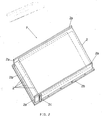
- the complete conveyor unit (1) complete with ionic filter (F)
- ionic filter (F) is fitted in the casing of a kitchen hood (as illustrated in figure 3); an additional ionic filter (F1) could be fitted close to the air conveyor outlet, in order to filter the air again before this is returned to the room.
- the filtering components that is the metal plates, of an exhaust fan fitted with ionic filters
- the filtering components are not subject to wear as in the case of active carbon cartridges, but at the most may be subject to become progressively dirty as a result of the repeated deposits of dirt transported in the air which is drawn;
- the structural shape of the ionic filter (F) has been designed to allow even the most inexperienced housewife to remove it easily and quickly in order to clean it, which as mentioned previously, need only be done once a year.
- the ionic filter (F) When the ionic filter (F) has been removed from the compartment (D), it can be washed easily by soaking in a solution of standard solvents.
- the electric system for operating the cleaning system can also be housed on the conveyor unit in question, in addition to the box housing the electronic system for the automatic operation of the unit, which switches on automatically when heat, kitchen odours, fumes and even gas leaks are detected.
- the filter (F) an alternative construction version of which is illustrated in fig. 5, while maintaining its box shape, could be fitted with two transverse opposite sides (2a) instead of longitudinal edges, for supporting the four rectangular overlying and straggered metal plates (2′), with a smaller width than that of the support sides (2a′) projecting from the base plate (2b′) made in moulded plastic material together with the above two edges.
- the staggered arrangement of the four metal plates (2′) makes the air passages alternated, one in front of the filter and the other, immediately above or below, at the back of the filter.
- This filter could also be fixed with release sliders instead of traditional screws, since the former are more practical and easier to move.
Landscapes
- Engineering & Computer Science (AREA)
- Chemical & Material Sciences (AREA)
- Combustion & Propulsion (AREA)
- Mechanical Engineering (AREA)
- General Engineering & Computer Science (AREA)
- External Artificial Organs (AREA)
- Separation Using Semi-Permeable Membranes (AREA)
- Ventilation (AREA)
- Filtering Of Dispersed Particles In Gases (AREA)
- Cleaning In General (AREA)
Priority Applications (1)
| Application Number | Priority Date | Filing Date | Title |
|---|---|---|---|
| AT89830351T ATE81903T1 (de) | 1988-08-05 | 1989-07-26 | Luftfoerderer fuer eine ionische filterhaube mit automatik oder mit handbedienung. |
Applications Claiming Priority (2)
| Application Number | Priority Date | Filing Date | Title |
|---|---|---|---|
| IT8800566U IT215797Z2 (it) | 1988-08-05 | 1988-08-05 | Blocco convogliatore per cappette con filtro depuratore ionico a comando manuale |
| IT56688U | 1988-08-05 |
Publications (3)
| Publication Number | Publication Date |
|---|---|
| EP0363329A2 true EP0363329A2 (fr) | 1990-04-11 |
| EP0363329A3 EP0363329A3 (en) | 1990-05-23 |
| EP0363329B1 EP0363329B1 (fr) | 1992-10-28 |
Family
ID=11099513
Family Applications (1)
| Application Number | Title | Priority Date | Filing Date |
|---|---|---|---|
| EP89830351A Expired - Lifetime EP0363329B1 (fr) | 1988-08-05 | 1989-07-26 | Dispositif de ventilation pour hottes avec un filtre de nettoyage ionique à commande manuelle ou automatique |
Country Status (4)
| Country | Link |
|---|---|
| EP (1) | EP0363329B1 (fr) |
| AT (1) | ATE81903T1 (fr) |
| ES (1) | ES2036842T3 (fr) |
| IT (1) | IT215797Z2 (fr) |
Cited By (3)
| Publication number | Priority date | Publication date | Assignee | Title |
|---|---|---|---|---|
| DE9311478U1 (de) * | 1993-08-02 | 1993-09-30 | BHL-Blechbearbeitungs GmbH, 73485 Unterschneidheim | Filtereinsatz für eine Dunstabzugshaube |
| US6820609B2 (en) * | 2002-04-03 | 2004-11-23 | Vent-A-Hood Ltd. | Low-profile ventilation hood |
| JP2014001862A (ja) * | 2012-06-15 | 2014-01-09 | Corona Corp | 燃焼装置 |
Family Cites Families (4)
| Publication number | Priority date | Publication date | Assignee | Title |
|---|---|---|---|---|
| US3678655A (en) * | 1969-06-03 | 1972-07-25 | Ronald N Rose | Electrostatic precipitator cell for desk or tabletop air purifier |
| DE2146288A1 (de) * | 1971-09-16 | 1973-03-22 | Bosch Hausgeraete Gmbh | Kuechendunstabzugshaube zum abscheiden von wrasen und verunreinigungen aus der raumluft |
| DE2832786A1 (de) * | 1977-07-29 | 1979-02-15 | Prl Soc | Dunstabzugshaube |
| IT1199766B (it) * | 1986-12-15 | 1988-12-30 | Mantini Franco | Depuratore d'aria elettrostatico particolarmente per cappe aspiranti da cucina |
-
1988
- 1988-08-05 IT IT8800566U patent/IT215797Z2/it active
-
1989
- 1989-07-26 EP EP89830351A patent/EP0363329B1/fr not_active Expired - Lifetime
- 1989-07-26 ES ES198989830351T patent/ES2036842T3/es not_active Expired - Lifetime
- 1989-07-26 AT AT89830351T patent/ATE81903T1/de not_active IP Right Cessation
Cited By (3)
| Publication number | Priority date | Publication date | Assignee | Title |
|---|---|---|---|---|
| DE9311478U1 (de) * | 1993-08-02 | 1993-09-30 | BHL-Blechbearbeitungs GmbH, 73485 Unterschneidheim | Filtereinsatz für eine Dunstabzugshaube |
| US6820609B2 (en) * | 2002-04-03 | 2004-11-23 | Vent-A-Hood Ltd. | Low-profile ventilation hood |
| JP2014001862A (ja) * | 2012-06-15 | 2014-01-09 | Corona Corp | 燃焼装置 |
Also Published As
| Publication number | Publication date |
|---|---|
| IT8800566V0 (it) | 1988-08-05 |
| IT215797Z2 (it) | 1990-11-14 |
| ATE81903T1 (de) | 1992-11-15 |
| ES2036842T3 (es) | 1993-06-01 |
| EP0363329A3 (en) | 1990-05-23 |
| EP0363329B1 (fr) | 1992-10-28 |
Similar Documents
| Publication | Publication Date | Title |
|---|---|---|
| US9474412B2 (en) | Smoke filter system for a cooking appliance | |
| US5211159A (en) | Exhaust hood with disposable filter assembly and filter-condition sensor | |
| US20030051725A1 (en) | Extractor hood | |
| US6656244B1 (en) | Fat removing labyrinth filter for aspirating hoods | |
| EP3380791B1 (fr) | Hotte à usage domestique | |
| EP3390918B1 (fr) | Hotte à usage domestique | |
| KR101614105B1 (ko) | 공기정화 및 순환기능을 갖는 직화 구이장치 | |
| WO2003000102A1 (fr) | Structure de machine electrique a griller la viande | |
| CN109691902A (zh) | 一种具有吸烟功能的电烤盘 | |
| KR102000918B1 (ko) | 무연후드 기능을 갖춘 상부가열식 구이기 | |
| EP0363329A2 (fr) | Dispositif de ventilation pour hottes avec un filtre de nettoyage ionique à commande manuelle ou automatique | |
| KR20050009557A (ko) | 공기 청정 기능이 제공되는 전자 레인지 | |
| CN205481225U (zh) | 一种油烟异味净化器 | |
| KR101970531B1 (ko) | 제연기가 구비된 자바라식 후드 | |
| CN209463627U (zh) | 一种简易厨房 | |
| KR102522380B1 (ko) | 친환경 학교 급식소 전용 급배기 시스템 및 작동방법 | |
| US5016612A (en) | Filtering hood for kitchen cookers, fitted with ionic filtering unit | |
| KR20180064640A (ko) | 가정용음식연기제거장치 | |
| CN220186921U (zh) | 一种家用直立式油烟机 | |
| CN218683842U (zh) | 一种隔绝油烟的肉类熟食炒料机 | |
| KR100903752B1 (ko) | 실내용 환기장치 | |
| CN210088936U (zh) | 一种机械复合分解静电油烟净化机组 | |
| JPH08182488A (ja) | 焙煎調理用器具の消煙装置 | |
| CN220397616U (zh) | 一种厨房油烟净化一体机 | |
| CN216147869U (zh) | 一种商用铁板烧 |
Legal Events
| Date | Code | Title | Description |
|---|---|---|---|
| PUAI | Public reference made under article 153(3) epc to a published international application that has entered the european phase |
Free format text: ORIGINAL CODE: 0009012 |
|
| PUAL | Search report despatched |
Free format text: ORIGINAL CODE: 0009013 |
|
| AK | Designated contracting states |
Kind code of ref document: A2 Designated state(s): AT BE CH DE ES FR GB GR LI LU NL SE |
|
| AK | Designated contracting states |
Kind code of ref document: A3 Designated state(s): AT BE CH DE ES FR GB GR LI LU NL SE |
|
| 17P | Request for examination filed |
Effective date: 19901115 |
|
| 17Q | First examination report despatched |
Effective date: 19910425 |
|
| GRAA | (expected) grant |
Free format text: ORIGINAL CODE: 0009210 |
|
| AK | Designated contracting states |
Kind code of ref document: B1 Designated state(s): AT BE CH DE ES FR GB GR LI LU NL SE |
|
| PG25 | Lapsed in a contracting state [announced via postgrant information from national office to epo] |
Ref country code: SE Effective date: 19921028 Ref country code: LI Effective date: 19921028 Ref country code: GR Free format text: LAPSE BECAUSE OF FAILURE TO SUBMIT A TRANSLATION OF THE DESCRIPTION OR TO PAY THE FEE WITHIN THE PRESCRIBED TIME-LIMIT Effective date: 19921028 Ref country code: CH Effective date: 19921028 Ref country code: BE Effective date: 19921028 Ref country code: AT Effective date: 19921028 |
|
| REF | Corresponds to: |
Ref document number: 81903 Country of ref document: AT Date of ref document: 19921115 Kind code of ref document: T |
|
| REF | Corresponds to: |
Ref document number: 68903323 Country of ref document: DE Date of ref document: 19921203 |
|
| REG | Reference to a national code |
Ref country code: CH Ref legal event code: PL |
|
| ET | Fr: translation filed | ||
| REG | Reference to a national code |
Ref country code: ES Ref legal event code: FG2A Ref document number: 2036842 Country of ref document: ES Kind code of ref document: T3 |
|
| PG25 | Lapsed in a contracting state [announced via postgrant information from national office to epo] |
Ref country code: LU Free format text: LAPSE BECAUSE OF NON-PAYMENT OF DUE FEES Effective date: 19930731 |
|
| PLBE | No opposition filed within time limit |
Free format text: ORIGINAL CODE: 0009261 |
|
| STAA | Information on the status of an ep patent application or granted ep patent |
Free format text: STATUS: NO OPPOSITION FILED WITHIN TIME LIMIT |
|
| 26N | No opposition filed | ||
| PGFP | Annual fee paid to national office [announced via postgrant information from national office to epo] |
Ref country code: FR Payment date: 19940719 Year of fee payment: 6 |
|
| PGFP | Annual fee paid to national office [announced via postgrant information from national office to epo] |
Ref country code: GB Payment date: 19940720 Year of fee payment: 6 |
|
| PGFP | Annual fee paid to national office [announced via postgrant information from national office to epo] |
Ref country code: ES Payment date: 19940727 Year of fee payment: 6 |
|
| PGFP | Annual fee paid to national office [announced via postgrant information from national office to epo] |
Ref country code: NL Payment date: 19940731 Year of fee payment: 6 |
|
| PGFP | Annual fee paid to national office [announced via postgrant information from national office to epo] |
Ref country code: DE Payment date: 19940927 Year of fee payment: 6 |
|
| PG25 | Lapsed in a contracting state [announced via postgrant information from national office to epo] |
Ref country code: GB Effective date: 19950726 |
|
| PG25 | Lapsed in a contracting state [announced via postgrant information from national office to epo] |
Ref country code: ES Free format text: LAPSE BECAUSE OF NON-PAYMENT OF DUE FEES Effective date: 19950727 |
|
| PG25 | Lapsed in a contracting state [announced via postgrant information from national office to epo] |
Ref country code: NL Effective date: 19960201 |
|
| GBPC | Gb: european patent ceased through non-payment of renewal fee |
Effective date: 19950726 |
|
| NLV4 | Nl: lapsed or anulled due to non-payment of the annual fee |
Effective date: 19960201 |
|
| PG25 | Lapsed in a contracting state [announced via postgrant information from national office to epo] |
Ref country code: DE Effective date: 19960402 |
|
| PG25 | Lapsed in a contracting state [announced via postgrant information from national office to epo] |
Ref country code: FR Effective date: 19960430 |
|
| REG | Reference to a national code |
Ref country code: FR Ref legal event code: ST |
|
| REG | Reference to a national code |
Ref country code: FR Ref legal event code: ST |
|
| REG | Reference to a national code |
Ref country code: FR Ref legal event code: ST |
|
| REG | Reference to a national code |
Ref country code: ES Ref legal event code: FD2A Effective date: 19960810 |