EP0361739B1 - Scanning apparatus for reading an image - Google Patents
Scanning apparatus for reading an image Download PDFInfo
- Publication number
- EP0361739B1 EP0361739B1 EP89309365A EP89309365A EP0361739B1 EP 0361739 B1 EP0361739 B1 EP 0361739B1 EP 89309365 A EP89309365 A EP 89309365A EP 89309365 A EP89309365 A EP 89309365A EP 0361739 B1 EP0361739 B1 EP 0361739B1
- Authority
- EP
- European Patent Office
- Prior art keywords
- line
- memory
- image signal
- digital
- line sensor
- Prior art date
- Legal status (The legal status is an assumption and is not a legal conclusion. Google has not performed a legal analysis and makes no representation as to the accuracy of the status listed.)
- Expired - Lifetime
Links
- 238000000034 method Methods 0.000 claims description 9
- 238000010586 diagram Methods 0.000 description 1
- 239000007787 solid Substances 0.000 description 1
Images


Classifications
-
- H—ELECTRICITY
- H04—ELECTRIC COMMUNICATION TECHNIQUE
- H04N—PICTORIAL COMMUNICATION, e.g. TELEVISION
- H04N1/00—Scanning, transmission or reproduction of documents or the like, e.g. facsimile transmission; Details thereof
- H04N1/387—Composing, repositioning or otherwise geometrically modifying originals
- H04N1/393—Enlarging or reducing
- H04N1/3935—Enlarging or reducing with modification of image resolution, i.e. determining the values of picture elements at new relative positions
-
- H—ELECTRICITY
- H04—ELECTRIC COMMUNICATION TECHNIQUE
- H04N—PICTORIAL COMMUNICATION, e.g. TELEVISION
- H04N1/00—Scanning, transmission or reproduction of documents or the like, e.g. facsimile transmission; Details thereof
- H04N1/387—Composing, repositioning or otherwise geometrically modifying originals
- H04N1/3877—Image rotation
Definitions
- This invention relates to a method of reading an image of a document.
- Such a method comprises the steps of: moving a line sensor and the document relative to each other, the line sensor having a plurality of aligned sensing devices and the direction of movement being at right angles to the direction of alignment of the sensing devices; obtaining a first analogue image signal from the line sensor comprising a plurality of lines of image data; analogue-to-digitally converting the first analogue image signal to produce a first digital image signal comprising a plurality of lines of a plurality of pixels of image data; writing, in a first writing mode, the first digital image signal to locations in a memory having row and column addresses so that each line of image data is written to a respective row of locations having the same row address; reading the memory to produce a second digital image signal; and digital-to-analoguely converting the second digital image signal to produce a second analogue image signal.
- one column line data stored in the memory may be converted by a coordinate converter so as to correspond to the lateral direction of the picture screen of the monitor, under control of the processing apparatus such as the computer (see Figure 1C).
- the processing apparatus such as the computer
- the method of the present invention is characterised by the steps of: providing a second writing mode which can be selected instead of the first writing mode; and in the second writing mode, writing the first digital image signal to locations in the memory so that each line of image data is written to a respective column of locations having the same column address.
- Patent Application EP-A-0 016 299 describes a way in which an image can be magnified or reduced in size.
- the method of the present invention may further comprise the steps of: selecting a magnifying mode; and, in the magnifying mode, writing the first digital image signal to locations in the memory so that each line of image data is written to a respective pair of rows or columns, as the case may be, of the memory. Also, the method of the present invention may further comprise the steps of: selecting a reducing mode; and, in the reducing mode, writing every other line of the first digital image signal to a respective row or column, as the case may be, of the memory.
- the scanning apparatus 1 of Figure 2 for reading an image is connected to a monitor receiver 10.
- a line sensor 2 such as a charge-coupled device (CCD), which is driven by a motor 6 so that it moves in the direction perpendicular to the longitudinal direction thereof.
- CCD charge-coupled device
- the line sensor 2 generates a line image signal as a sequence signal or a simultaneous signal of a picture element signal.
- This line image signal is supplied to an analogue-to-digital (A/D) converter 3, in which it is converted to a digital line image signal.
- the sequence signal of the line image signal from the line sensor 2 forms a two-dimensional image signal, accordingly, the sequence signal of the digital line image signal from the A/D converter 3 forms a digital two-dimensional image signal.
- the A/D converter 3 is supplied with a clock signal from a timing generator 7.
- the digital two-dimensional image signal formed of the sequence signal of the digital image signal read from the memory 4 is supplied to a digital-to-analogue (D/A) converter 5, in which it is converted to an analogue two-dimensional image signal.
- the analogue-two-dimensional signal from the D/A converter 5 is supplied through a terminal T to the monitor 10.
- the D/A converter 5 is supplied with the clock signal from the timing generator 7.
- the digital image signal is a binary signal for simplicity, but the digital image signal is not limited to a binary signal but may for example be a multilevel signal such as an 8-bit signal.
- Figures 6A to 6L show respective pixel storing portions storing digital image signals.
- a hatched square portion represents a portion in which a digital image signal is not yet stored
- an open square portion represents a portion in which a digital image signal [0] corresponding to white is stored
- a solid square portion represents a portion in which a digital image signal [1] corresponding to black is stored.
- the line image signals from the line sensor 2 are converted to the digital line image signals by the A/D converter 3 and are respectively written in the memory 4 at its pixel storing portions designated by addresses (1, 5) to (6, 5) as shown in Figure 6H.
- the line image signals from the line sensor 2 are converted to the digital line signals by the A/D converter 3 and are respectively written in the memory 4 at its pixel storing portions designated by addresses (1, 3) to (6, 3) as shown in Figure 6J.
- the two-dimensional image of the two-dimensional image signal derived by scanning the document can be selectively displayed in the original condition or in the condition rotated by 180° by writing the digitized signal of the line image signal from the line sensor 2 in the two-dimension memory 4 at its six vertically-aligned pixel storing portions from either left to right or from right to left in Figure 6.
- the two-dimensional image of the two-dimensional image signal obtained by scanning the document can be selectively displayed in the original orientation, or rotated by 90° or rotated by 180°.
- the magnifying mode will be explained first.
- the pixel storing portion of the memory 4 is assumed to be formed of 12 x 12 but the line sensor 2 is formed of six pixel sensor portions.
- the two-dimensional image on the document is formed of 6 x 6 pixels similary to Figure 5.
- Figures 7A and 7B show the condition in which image data are stored in the memory 4.
- the central 6 x 6 pixel storing portions represented by xy coordinates (4, 4) to (9, 9) are used as normal storage areas, wherein in the normal mode (magnify-by-one mode) the digitized signals of the line image signals from the line sensor 2 are stored in the normal storage areas by operations similar to those as shown in Figure 7A.
- the whole of 12 x 12 pixel storage portions of the memory 4 is used as a magnifying storage area, whereby in the magnifying (magnify-by-two) mode the digitized signals of the line image signals formed of 6 pixel signals from the line sensor 2 are sequentially written in two columns of pixel storage portions (24 pixel storage portions in total) in the vertical direction of the memory 4 from left to right.
- the memory 4 stores a two-dimensional image signal which is magnified twice in the vertical and horizontal directions, as shown in Figure 7B.
- central 6 x 6 pixel storage portions represented by xy coordinates (4, 4) to (9, 9) are used as reducing storage areas, wherein in the reducing mode (reduce-to-1/2) the line image signals formed of every other pixel signal of the digitized signals of the line image signal formed of twelve pixel signals derived from the line sensor 2 are sequentially written in every other line address of 6 pixel storage portions of the reducing storage area of the memory 4 from left to right.
- the line sensor 2 scans the document having the same two-dimensional image as that of Figure 7B, then a two-dimensional image, which is reduced to 1/2 in size in the horizontal and vertical directions, is stored in the memory 4 as shown in Figure 7A.
- the present invention is particularly suitable for application to the above image scanning apparatus in which the line sensor scans the rectangular, standardized document along the longitudinal direction thereof and the line sensor supplies the two-dimensional image signal composed of successive line image signals, the invention is not limited to this application.
Description
- This invention relates to a method of reading an image of a document.
- Such a method, which is understood to be known, comprises the steps of:
moving a line sensor and the document relative to each other, the line sensor having a plurality of aligned sensing devices and the direction of movement being at right angles to the direction of alignment of the sensing devices;
obtaining a first analogue image signal from the line sensor comprising a plurality of lines of image data;
analogue-to-digitally converting the first analogue image signal to produce a first digital image signal comprising a plurality of lines of a plurality of pixels of image data;
writing, in a first writing mode, the first digital image signal to locations in a memory having row and column addresses so that each line of image data is written to a respective row of locations having the same row address;
reading the memory to produce a second digital image signal; and
digital-to-analoguely converting the second digital image signal to produce a second analogue image signal. - When the line sensor scans the document along the lateral direction thereof, if one line of the short side of the image data is stored in the memory in a storage area of one column line direction, the image data of one column line from the memory are displayed so as to become identical with the short side of the picture screen (see Figure 1A).
- However, if a document oriented with its short sides in the up and down direction is scanned by the line sensor and the image data is displayed similarly as described above, the image is displayed such that it is turned laterally (see Figure 1B).
- With the arrangement of Figure 1B, in order to enable the image to be displayed the right way up, one column line data stored in the memory may be converted by a coordinate converter so as to correspond to the lateral direction of the picture screen of the monitor, under control of the processing apparatus such as the computer (see Figure 1C). However, the required overall system to do this is expensive.
- The method of the present invention is characterised by the steps of:
providing a second writing mode which can be selected instead of the first writing mode; and
in the second writing mode, writing the first digital image signal to locations in the memory so that each line of image data is written to a respective column of locations having the same column address. - Patent Application EP-A-0 016 299 describes a way in which an image can be magnified or reduced in size.
- The method of the present invention may further comprise the steps of: selecting a magnifying mode; and, in the magnifying mode, writing the first digital image signal to locations in the memory so that each line of image data is written to a respective pair of rows or columns, as the case may be, of the memory. Also, the method of the present invention may further comprise the steps of: selecting a reducing mode; and, in the reducing mode, writing every other line of the first digital image signal to a respective row or column, as the case may be, of the memory.
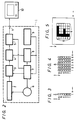
- The invention will now be described by way of example with reference to the accompanying drawings, throughout which like parts are referred to by like references, and in which:
- Figures 1A to 1C are schematic views referred to in explaining a known scanning apparatus;
- Figure 2 is a block diagram of an embodiment of scanning apparatus according to the present invention;
- Figure 3 is a schematic representation of a line sensor;
- Figure 4 is a schematic representation of a memory;
- Figure 5 is a schematic representation of a document to be scanned;
- Figures 6A to 6L are schematic representations of storage portions of the memory; and
- Figures 7A and 7B are schematic representations of storage portions of the memory for explaining a magnifying mode and a reducing mode, respectively.
- The
scanning apparatus 1 of Figure 2 for reading an image is connected to amonitor receiver 10. - In the
scanning apparatus 1, there is provided aline sensor 2 such as a charge-coupled device (CCD), which is driven by amotor 6 so that it moves in the direction perpendicular to the longitudinal direction thereof. - The
line sensor 2 generates a line image signal as a sequence signal or a simultaneous signal of a picture element signal. This line image signal is supplied to an analogue-to-digital (A/D)converter 3, in which it is converted to a digital line image signal. The sequence signal of the line image signal from theline sensor 2 forms a two-dimensional image signal, accordingly, the sequence signal of the digital line image signal from the A/D converter 3 forms a digital two-dimensional image signal. The A/D converter 3 is supplied with a clock signal from atiming generator 7. - The digital two-dimensional image signal formed of the sequence signal of the digital line image signal from the A/
D converter 3 is written in a two-dimension memory 4 and stored therein. Thememory 4 is supplied with a write and read control signal from amemory controller 8, and is thereby controlled in its write and read operation. Thememory controller 8 includes an address control circuit (not shown) which appoints addresses upon reading and writing the image signal from thememory 4. The address signal from the address control circuit is supplied to thememory 4. Thememory controller 8 is supplied with write and read clock signals from thetiming generator 7, and its address control circuit generates write and read address signals on the basis of the write and read clock signals. - The digital two-dimensional image signal formed of the sequence signal of the digital image signal read from the
memory 4 is supplied to a digital-to-analogue (D/A)converter 5, in which it is converted to an analogue two-dimensional image signal. The analogue-two-dimensional signal from the D/A converter 5 is supplied through a terminal T to themonitor 10. The D/A converter 5 is supplied with the clock signal from thetiming generator 7. - A row-line and column-line
mode switching circuit 9 generates a switching signal which is supplied to thetiming generator 7 and to thememory controller 8, whereby the write address in which the line image signal from theline sensor 2 is written in thememory 4 is switched as will be described later. - The operation will now be described with reference to Figures 3 to 6. In the following explanation, the digital image signal is a binary signal for simplicity, but the digital image signal is not limited to a binary signal but may for example be a multilevel signal such as an 8-bit signal.
- The
line sensor 2 is shown in Figure 3, and it is assumed that it is formed of six pixel sensor portions aligned in the y direction of an xy orthogonal coordinate system, and the six pixel sensor portions are represented by xy coordinates (1, 1), (1, 2), ..., (1, 6), respectively. - The
memory 4 is shown in Figure 4, and it is assumed that it is formed of 6 x 6 pixel storing portions to correspond with theline sensor 2. The 6 x 6 pixel storing portions are represented by xy coordinates (1, 1), ..., (6, 6), respectively. - Figure 5 shows a document, and it is assumed that it is formed of 6 x 6 pixels which form a two-dimensional image whose configuration is square, to correspond with the
line sensor 2 and thememory 4. This two-dimensional image includes a character [F] which placed correctly is as shown in Figure 5. - Figures 6A to 6L show respective pixel storing portions storing digital image signals. Throughout Figures 6A to 6L, a hatched square portion represents a portion in which a digital image signal is not yet stored, an open square portion represents a portion in which a digital image signal [0] corresponding to white is stored, and a solid square portion represents a portion in which a digital image signal [1] corresponding to black is stored.
- The operation when the
mode switching circuit 9 is switched to the row-line mode will now be described. In this case, it is assumed that theline sensor 2 scans the two-dimensional image on the document in the x direction, that is, from left to right in Figure 5. - When the
line sensor 2 scans six pixels on the first column from the left of the picture shown in Figure 5, then the line image signals from theline sensor 2 are converted to the digital line image signals by the A/D converter 3, and are respectively written in thememory 4 at its pixel storing portions designated by addresses (1, 1) to (1, 6) as shown in Figure 6A. - When the
line sensor 2 scans six pixels on the second column from the left of the picture shown in Figure 5, then the line image signals from theline sensor 2 are converted to the digital line image signals by the A/D converter 3, and are respectively written in thememory 4 at its pixel storing portions designated by addresses (2, 1) to (2, 6) as shown in Figure 6B. - When the
line sensor 2 scans six pixels on the third column from the left of the picture shown in Figure 5, then the line image signals from theline sensor 2 are converted to the digital line image signals by the A/D converter 3, and are respectively written in thememory 4 at its pixel storing portions designated by addresses (3, 1) to (3, 6) as shown in Figure 6C. - When the
line sensor 2 scans six pixels on the fourth column from the left of the picture shown in Figure 5, then the line image signals from theline sensor 2 are converted to the digital line image signals by the A/D converter 3, and are respectively written in thememory 4 at its pixel storing portions designed by addresses (4, 1) to (4, 6) as shown in Figure 6D. - When the
line sensor 2 scans six pixels on the fifth column from the left of the picture shown in Figure 5, then the line image signals from theline sensor 2 are converted to the digital line image signals by the A/D converter 3, and are respectively written in thememory 4 at its pixel storing portions designated by addresses (5, 1) to (5, 6) as shown in Figure 6E. - When the
line sensor 2 scans six pixels on the sixth column from the left of the picture shown in Figure 5, then the line image signals from theline sensor 2 are converted to the digital line image signals by the A/D converter 3, and are respectively stored in thememory 4 at its pixel storing portions designated by addresses (6, 1) to (6, 6) as shown in Figure 6F. - Thus, when the digital image signals stored in the pixel storing portions of the
memory 4 are sequentially read out in the order of addresses (1, 6), (2, 6), ..., (6, 6), (1, 5), ..., (6, 5), (1, 4), (2, 4), ..., (6, 4), ..., (1, 1), (2, 1), ..., (6, 1), converted to analogue pixel signals by the D/A converter 5, and are fed to themonitor 10, then a two-dimensional picture including the character [F], correctly oriented, is displayed on the display screen of themonitor 10. - The operation when the
mode switching circuit 9 is switched to the column-line mode will be described next. In this case, it is assumed that theline sensor 2 scans the two-dimensional image of the document from left to right in the x direction shown in Figure 5. - When the
line sensor 2 scans six pixels on the first column from the left of the picture, then the line image signals from theline sensor 2 are converted to the digital line image signals by the A/D converter 3, and are respectively written in thememory 4 at its pixel storing portions designated by addresses (1, 6) to (6, 6) as shown in Figure 6G. - When the
line sensor 2 scans six pixels on the second column from the left of the picture, then the line image signals from theline sensor 2 are converted to the digital line image signals by the A/D converter 3 and are respectively written in thememory 4 at its pixel storing portions designated by addresses (1, 5) to (6, 5) as shown in Figure 6H. - When the
line sensor 2 scans six pixels on the third column from the left of the picture, then the line image signals from theline sensor 2 are converted to the digital line signals by the A/D converter 3 and are respectively written in thememory 4 at its pixel storing portions designated by addresses (1, 4) to (6, 4) as shown in Figure 6I. - When the
line sensor 2 scans six pixels on the fourth column from the left of the picture, then the line image signals from theline sensor 2 are converted to the digital line signals by the A/D converter 3 and are respectively written in thememory 4 at its pixel storing portions designated by addresses (1, 3) to (6, 3) as shown in Figure 6J. - When the
line sensor 2 scans six pixels on the fifth column from the left of the picture, then the line image signals from theline sensor 2 are converted to the digital line signals by the A/D converter 3 and are respectively written in thememory 4 at its pixel storing portions designated by addresses (1, 2) to (6, 2) as shown in Figure 6K. - When the
line sensor 2 scans six pixels on the sixth column from the left of the picture, then the line image signals from theline sensor 2 are converted to the digital line signals by the A/D converter 3 and are respectively written in thememory 4 at its pixel storing portions designated by addresses (1, 1) to (6, 1) as shown in Figure 6L. - Thus, when the digital pixel signals of the respective pixel storing portions of the
memory 4 are sequentially read out in the order of (1, 6), (2, 6), ..., (6, 6), (1, 5), ..., (6, 5), (1, 4), (2, 4), ..., (6, 4), ..., (1, 1), (2, 1), ..., (6, 1), fed to the D/A converter 5, in which they are converted to the analogue pixel signals and then are fed to themonitor 10, a two-dimensional picture including a character [F], which is rotated by 90° in the clockwise direction, is displayed on the picture screen of themonitor 10. - In this embodiment, when the digitized signals of the line image signal from the
line sensor 2 are written in the six vertically-aligned pixel storing portions of the two-dimension memory 4 from left to right in Figure 6, or when the digitized signals are written in thememory 4 at its six horizontally-aligned pixel storing portions from top to bottom in Figure 6, the two-dimensional image of the two-dimensional image signal read out of the document can be selectively arranged in the same direction or it can be rotated by 90°. The two-dimensional image of the two-dimensional image signal derived by scanning the document can be selectively displayed in the original condition or in the condition rotated by 180° by writing the digitized signal of the line image signal from theline sensor 2 in the two-dimension memory 4 at its six vertically-aligned pixel storing portions from either left to right or from right to left in Figure 6. Moreover, by the combination of the above-mentioned manners, the two-dimensional image of the two-dimensional image signal obtained by scanning the document can be selectively displayed in the original orientation, or rotated by 90° or rotated by 180°. - A magnifying mode and a reducing mode in which the two-dimensional image signal, obtained by scanning the document, is magnified or reduced in size will now be described with reference to Figures 7A and 7B.
- The magnifying mode will be explained first. The pixel storing portion of the
memory 4 is assumed to be formed of 12 x 12 but theline sensor 2 is formed of six pixel sensor portions. In this case, the two-dimensional image on the document is formed of 6 x 6 pixels similary to Figure 5. - Figures 7A and 7B show the condition in which image data are stored in the
memory 4. Of 12 x 12 pixel storing portions in thememory 4, the central 6 x 6 pixel storing portions represented by xy coordinates (4, 4) to (9, 9) are used as normal storage areas, wherein in the normal mode (magnify-by-one mode) the digitized signals of the line image signals from theline sensor 2 are stored in the normal storage areas by operations similar to those as shown in Figure 7A. Moreover, the whole of 12 x 12 pixel storage portions of thememory 4 is used as a magnifying storage area, whereby in the magnifying (magnify-by-two) mode the digitized signals of the line image signals formed of 6 pixel signals from theline sensor 2 are sequentially written in two columns of pixel storage portions (24 pixel storage portions in total) in the vertical direction of thememory 4 from left to right. Thus, when theline sensor 2 scans the document having the two-dimensional image, thememory 4 stores a two-dimensional image signal which is magnified twice in the vertical and horizontal directions, as shown in Figure 7B. - The reducing mode will now be explained. Again, the
memory 4 is assumed to comprise 12 x 12 pixel storage portions, and in correspondence therewith, theline sensor 2 is comprised of twelve pixel sensor portions. In this event, the two-dimensional picture of the document is formed of 12 x 12 pixels. All the 12 x 12 pixel storage portions of thememory 4 are used as a normal storage area, whereby in the normal mode (magnify-by-one mode) the digitized signals of the line image signal derived from theline sensor 2 are written in the normal storage area by operations similar to those as shown in Figure 7B. Moreover, of the 12 x 12 pixel storage areas of thememory 4, central 6 x 6 pixel storage portions, represented by xy coordinates (4, 4) to (9, 9) are used as reducing storage areas, wherein in the reducing mode (reduce-to-1/2) the line image signals formed of every other pixel signal of the digitized signals of the line image signal formed of twelve pixel signals derived from theline sensor 2 are sequentially written in every other line address of 6 pixel storage portions of the reducing storage area of thememory 4 from left to right. Thus, when theline sensor 2 scans the document having the same two-dimensional image as that of Figure 7B, then a two-dimensional image, which is reduced to 1/2 in size in the horizontal and vertical directions, is stored in thememory 4 as shown in Figure 7A. - By the combination of the magnifying mode and the reducing mode, it is possible to change the displayed orientation and condition of the two-dimensional image of the two-dimensional image signal in five ways.
- The magnifying ratio and the reducing ratio are not limited to those as described above and may be selected freely.
- Although the present invention is particularly suitable for application to the above image scanning apparatus in which the line sensor scans the rectangular, standardized document along the longitudinal direction thereof and the line sensor supplies the two-dimensional image signal composed of successive line image signals, the invention is not limited to this application.
- While the line sensor is moved so as to scan the document in the above embodiment, it is possible for a document on a document holder to be moved relative to the line sensor.
- Embodiments of the present invention, can provide an apparatus for reading an image in which without using a memory of large capacity and a processing apparatus such as a computer, the modes in which the two-dimensional image of the two-dimensional image signal formed of the line image signals sequentially read by the line sensor is located can be changed with ease.
Claims (4)
- A method of reading an image of a document, comprising the steps of:
moving a line sensor and the document relative to each other, the line sensor having a plurality of aligned sensing devices and the direction of movement being at right angles to the direction of alignment of the sensing devices;
obtaining a first analogue image signal from the line sensor comprising a plurality of lines of image data;
analogue-to-digital converting the first analogue image signal to produce a first digital image signal comprising a plurality of lines of a plurality of pixels of image data;
writing, in a first writing mode, the first digital image signal to locations in a memory having row and column addresses so that each line of image data is written to a respective row of locations having the same row address;
reading the memory to produce a second digital image signal; and
digital-to-analogue converting the second digital image signal to produce a second analogue image signal;
characterised by the steps of:
providing a second writing mode which can be selected instead of the first writing mode; and
in the second writing mode, writing the first digital image signal to locations in the memory so that each line of image data is written to a respective column of locations having the same column address. - A method according to claim 1 further comprising the step of supplying the second analogue image signal to a monitor.
- A method according to claim 1 or 2, further comprising the steps of: selecting a magnifying mode; and, in the magnifying mode, writing the first digital image signal to locations in the memory so that each line of image data is written to a respective pair of rows or columns, as the case may be, of the memory.
- A method according to any preceding claim, further comprising the steps of: selecting a reducing mode; and, in the reducing mode, writing every other line of the first digital image signal to a respective row or column, as the case may be, of the memory.
Applications Claiming Priority (2)
| Application Number | Priority Date | Filing Date | Title |
|---|---|---|---|
| JP63245510A JPH0292155A (en) | 1988-09-29 | 1988-09-29 | Picture reader |
| JP245510/88 | 1988-09-29 |
Publications (3)
| Publication Number | Publication Date |
|---|---|
| EP0361739A2 EP0361739A2 (en) | 1990-04-04 |
| EP0361739A3 EP0361739A3 (en) | 1991-01-09 |
| EP0361739B1 true EP0361739B1 (en) | 1994-12-28 |
Family
ID=17134754
Family Applications (1)
| Application Number | Title | Priority Date | Filing Date |
|---|---|---|---|
| EP89309365A Expired - Lifetime EP0361739B1 (en) | 1988-09-29 | 1989-09-14 | Scanning apparatus for reading an image |
Country Status (5)
| Country | Link |
|---|---|
| US (1) | US5133025A (en) |
| EP (1) | EP0361739B1 (en) |
| JP (1) | JPH0292155A (en) |
| KR (1) | KR0131139B1 (en) |
| DE (1) | DE68920248T2 (en) |
Families Citing this family (17)
| Publication number | Priority date | Publication date | Assignee | Title |
|---|---|---|---|---|
| US6115543A (en) * | 1989-11-01 | 2000-09-05 | Canon Kabushiki Kaisha | Data communication apparatus having a handy scanner |
| NL9002110A (en) * | 1990-09-19 | 1992-04-16 | Koninkl Philips Electronics Nv | IMAGE SEARCH AND DISPLAY SYSTEM AND A REGISTRATION BEARING CODED IMAGES, METHOD FOR RECORDING ENCRYPTED IMAGES AND A SEARCH AND DISPLAY DEVICE. |
| AU655944B2 (en) * | 1990-09-19 | 1995-01-19 | Philips Electronics N.V. | Read device |
| JP3110041B2 (en) * | 1990-11-30 | 2000-11-20 | 株式会社東芝 | Image information processing device |
| US5799318A (en) * | 1993-04-13 | 1998-08-25 | Firstfloor Software | Method and apparatus for collecting and displaying information from diverse computer resources |
| JPH07152528A (en) * | 1993-11-26 | 1995-06-16 | Fujitsu Ltd | Screen scroll device/method |
| JP3492761B2 (en) | 1994-04-07 | 2004-02-03 | 株式会社ソニー・コンピュータエンタテインメント | Image generation method and apparatus |
| US5598181A (en) * | 1994-09-26 | 1997-01-28 | Xerox Corporation | Method and apparatus for rotating a digital image ninety degrees using a small auxiliary buffer |
| JPH10173917A (en) * | 1996-10-11 | 1998-06-26 | Nikon Corp | Image read system, image reader and storage medium storing control procedure |
| US5973734A (en) | 1997-07-09 | 1999-10-26 | Flashpoint Technology, Inc. | Method and apparatus for correcting aspect ratio in a camera graphical user interface |
| US6330374B1 (en) * | 1998-11-13 | 2001-12-11 | Ricoh Company, Ltd. | Image manipulation for a digital copier which operates on a block basis |
| US6317141B1 (en) | 1998-12-31 | 2001-11-13 | Flashpoint Technology, Inc. | Method and apparatus for editing heterogeneous media objects in a digital imaging device |
| US6842265B1 (en) * | 2000-09-29 | 2005-01-11 | Hewlett-Packard Development Company, L.P. | Method and apparatus for controlling image orientation of scanner apparatus |
| US9224145B1 (en) | 2006-08-30 | 2015-12-29 | Qurio Holdings, Inc. | Venue based digital rights using capture device with digital watermarking capability |
| JP2008085450A (en) * | 2006-09-26 | 2008-04-10 | Kyocera Mita Corp | Image forming apparatus |
| US20110234636A1 (en) * | 2010-03-24 | 2011-09-29 | Dsp Group Ltd. | Method and integrated circuit for image manipulation |
| JP5760703B2 (en) * | 2011-05-30 | 2015-08-12 | 株式会社リコー | Image processing apparatus, image processing program, and recording medium |
Family Cites Families (11)
| Publication number | Priority date | Publication date | Assignee | Title |
|---|---|---|---|---|
| US3976982A (en) * | 1975-05-12 | 1976-08-24 | International Business Machines Corporation | Apparatus for image manipulation |
| ZA797059B (en) * | 1979-03-23 | 1980-11-26 | Ibm | System for and method of reproducing an image |
| US4453268A (en) * | 1981-03-18 | 1984-06-05 | Lundy Electronics & Systems, Inc. | OCR Page reader |
| JPH0744641B2 (en) * | 1983-06-06 | 1995-05-15 | キヤノン株式会社 | Image scaling processor |
| JPS6294073A (en) * | 1985-10-18 | 1987-04-30 | Sanyo Electric Co Ltd | Facsimile equipment |
| JPH083851B2 (en) * | 1986-01-13 | 1996-01-17 | 株式会社東芝 | Image processing device |
| JPS62258455A (en) * | 1986-05-01 | 1987-11-10 | Toppan Printing Co Ltd | Image writing and reading system |
| US4819190A (en) * | 1986-06-18 | 1989-04-04 | The United States Of America As Represented By The Secretary Of The Navy | Video line processor |
| JP2575661B2 (en) * | 1986-08-13 | 1997-01-29 | キヤノン株式会社 | Image memory |
| JPS647759A (en) * | 1987-05-11 | 1989-01-11 | Nippon Sheet Glass Co Ltd | Image pattern expanding device |
| DE68916049T2 (en) * | 1988-02-05 | 1994-09-22 | Fuji Photo Film Co Ltd | Method and apparatus for viewing color photographic films. |
-
1988
- 1988-09-29 JP JP63245510A patent/JPH0292155A/en active Pending
-
1989
- 1989-08-23 KR KR1019890011968A patent/KR0131139B1/en not_active IP Right Cessation
- 1989-09-14 DE DE68920248T patent/DE68920248T2/en not_active Expired - Fee Related
- 1989-09-14 EP EP89309365A patent/EP0361739B1/en not_active Expired - Lifetime
- 1989-09-26 US US07/412,432 patent/US5133025A/en not_active Expired - Fee Related
Also Published As
| Publication number | Publication date |
|---|---|
| KR900005795A (en) | 1990-04-14 |
| JPH0292155A (en) | 1990-03-30 |
| DE68920248T2 (en) | 1995-05-04 |
| EP0361739A2 (en) | 1990-04-04 |
| DE68920248D1 (en) | 1995-02-09 |
| US5133025A (en) | 1992-07-21 |
| KR0131139B1 (en) | 1998-04-16 |
| EP0361739A3 (en) | 1991-01-09 |
Similar Documents
| Publication | Publication Date | Title |
|---|---|---|
| EP0361739B1 (en) | Scanning apparatus for reading an image | |
| US5798750A (en) | Image display apparatus | |
| US4949189A (en) | Two-sided document scanning apparatus | |
| JPS61214072A (en) | Image processor | |
| WO1997005573A1 (en) | Run-length encoded image rotation | |
| US5195174A (en) | Image data processing apparatus capable of composing one image from a plurality of images | |
| EP0260997B1 (en) | Improvements in and relating to the processing of video image signals | |
| US6046753A (en) | Electronic image processing system for modifying initial image data | |
| EP0488441B1 (en) | Image storage device and image processing device comprising the image storage device | |
| EP0381064A2 (en) | Addressing mechanism for accessing multiple neighboring locations from full field memory in parallel | |
| KR960030683A (en) | Interpolator | |
| EP0687994A2 (en) | Contour-information extraction apparatus and method | |
| JP2559710B2 (en) | Image processing method | |
| JPH03239067A (en) | Image reader | |
| JPH06101844B2 (en) | Image processing device | |
| JP2839768B2 (en) | Image rotation circuit | |
| JPH0132956B2 (en) | ||
| EP1624440A1 (en) | Image display device with plural signal output circuits | |
| JPH0232478A (en) | Image memory for parallel access | |
| JPH0523462B2 (en) | ||
| JPH01162482A (en) | Picture input device | |
| JPH06338998A (en) | Image dealing device | |
| JPH0544704B2 (en) | ||
| GB2204468A (en) | Display systems | |
| JPH0779383A (en) | Picture processing unit |
Legal Events
| Date | Code | Title | Description |
|---|---|---|---|
| PUAI | Public reference made under article 153(3) epc to a published international application that has entered the european phase |
Free format text: ORIGINAL CODE: 0009012 |
|
| AK | Designated contracting states |
Kind code of ref document: A2 Designated state(s): DE FR GB |
|
| PUAL | Search report despatched |
Free format text: ORIGINAL CODE: 0009013 |
|
| AK | Designated contracting states |
Kind code of ref document: A3 Designated state(s): DE FR GB |
|
| 17P | Request for examination filed |
Effective date: 19910502 |
|
| 17Q | First examination report despatched |
Effective date: 19930915 |
|
| GRAA | (expected) grant |
Free format text: ORIGINAL CODE: 0009210 |
|
| AK | Designated contracting states |
Kind code of ref document: B1 Designated state(s): DE FR GB |
|
| REF | Corresponds to: |
Ref document number: 68920248 Country of ref document: DE Date of ref document: 19950209 |
|
| ET | Fr: translation filed | ||
| PLBE | No opposition filed within time limit |
Free format text: ORIGINAL CODE: 0009261 |
|
| STAA | Information on the status of an ep patent application or granted ep patent |
Free format text: STATUS: NO OPPOSITION FILED WITHIN TIME LIMIT |
|
| 26N | No opposition filed | ||
| PGFP | Annual fee paid to national office [announced via postgrant information from national office to epo] |
Ref country code: FR Payment date: 20010911 Year of fee payment: 13 |
|
| PGFP | Annual fee paid to national office [announced via postgrant information from national office to epo] |
Ref country code: GB Payment date: 20010912 Year of fee payment: 13 |
|
| PGFP | Annual fee paid to national office [announced via postgrant information from national office to epo] |
Ref country code: DE Payment date: 20011001 Year of fee payment: 13 |
|
| REG | Reference to a national code |
Ref country code: GB Ref legal event code: IF02 |
|
| PG25 | Lapsed in a contracting state [announced via postgrant information from national office to epo] |
Ref country code: GB Free format text: LAPSE BECAUSE OF NON-PAYMENT OF DUE FEES Effective date: 20020914 |
|
| PG25 | Lapsed in a contracting state [announced via postgrant information from national office to epo] |
Ref country code: DE Free format text: LAPSE BECAUSE OF NON-PAYMENT OF DUE FEES Effective date: 20030401 |
|
| GBPC | Gb: european patent ceased through non-payment of renewal fee |
Effective date: 20020914 |
|
| PG25 | Lapsed in a contracting state [announced via postgrant information from national office to epo] |
Ref country code: FR Free format text: LAPSE BECAUSE OF NON-PAYMENT OF DUE FEES Effective date: 20030603 |
|
| REG | Reference to a national code |
Ref country code: FR Ref legal event code: ST |