EP0361340A1 - Conveyor system for moving materials and semi-worked items - Google Patents
Conveyor system for moving materials and semi-worked items Download PDFInfo
- Publication number
- EP0361340A1 EP0361340A1 EP89117611A EP89117611A EP0361340A1 EP 0361340 A1 EP0361340 A1 EP 0361340A1 EP 89117611 A EP89117611 A EP 89117611A EP 89117611 A EP89117611 A EP 89117611A EP 0361340 A1 EP0361340 A1 EP 0361340A1
- Authority
- EP
- European Patent Office
- Prior art keywords
- rail
- runway
- conveyor system
- trolley
- rollers
- Prior art date
- Legal status (The legal status is an assumption and is not a legal conclusion. Google has not performed a legal analysis and makes no representation as to the accuracy of the status listed.)
- Granted
Links
Images

Classifications
-
- B—PERFORMING OPERATIONS; TRANSPORTING
- B65—CONVEYING; PACKING; STORING; HANDLING THIN OR FILAMENTARY MATERIAL
- B65G—TRANSPORT OR STORAGE DEVICES, e.g. CONVEYORS FOR LOADING OR TIPPING, SHOP CONVEYOR SYSTEMS OR PNEUMATIC TUBE CONVEYORS
- B65G54/00—Non-mechanical conveyors not otherwise provided for
- B65G54/02—Non-mechanical conveyors not otherwise provided for electrostatic, electric, or magnetic
Definitions
- the present invention relates to a conveyor system particularly for moving materials and semi-worked items.
- the second requirement forces the installation of considerably powerful motor-reducer assemblies on the trolleys, which assemblies are thus greatly oversized for the steps of advancement at constant speed.
- This entails the following disadvantages: - considerable bulk of the propulsion systems, - limited efficiency, due both to the power losses caused by the transmission of the motion and to the efficiency of the motors, which must be under-powered in the steps of motion at constant speed, - mechanical complications of the structure of the trolleys, with consequent high installation and management costs, - difficulty in checking the parameters of the motion of the trolleys when speed variations or modifications are required after the installation of the system.
- the transmission of power is furthermore limited by the friction coefficient between the driving rollers and the rail of the runway; this circumstance limits the value of the trolley start-up and stop accelerations on one hand and requires the accurate maintenance of the rolling surfaces and of the rollers, on the other, to prevent the reduction of the value of the friction coefficient for example due to the presence of a film of lubricant and/or condensed moisture and/or dust or the like.
- the aim of the present invention is to eliminate these disadvantages, and within this general aim the invention has the following important particular objects: - to eliminate the presence of the motor reducer assemblies installed on the trolleys and to make the power transmission independent from the value of the friction coefficient between the runway and the rollers of the trolleys, - to significantly reduce the weight and bulk of the trolleys and, at the same time, considerably simplify their structure, with corresponding significant advantages both in terms of power consumption and in terms of installation and maintenance costs, - to make the conveyor system insensitive to the weather and atmospheric conditions of the work environment, in particular to the presence of moisture, of particles of suspended materials such as lubricants, paints, powders and the like, - to make the conveyor system more flexible, in that it allows to program the values of the speeds and accelerations of the individual trolleys in the different portions of the path.
- the reference numeral 10 indicates the armature, which is constituted by the conveyor system runway itself, and 11 indicates the inductor, which is constituted by a magnetizable core M rigidly associated with each individual trolley of the conveyor; the armature and the inductor are separated by an air gap "t".
- the armature 10 comprises a ferromagnetic portion 12 which coincides with the rail of the runway or with a part thereof, and a plate 13 made of conducting non-magnetic material, advantageously aluminum, stably coupled to the portion 12.
- the magnetic core M of the inductor 11 is provided with the exciter windings 14, which are advantageously of the three-phase type and are accommodated in a per se known manner in respective recesses (not illustrated) which define corresponding polar expansions (also not illustrated) of the core which are arranged facing the armature 10; the excitation current is fed to the windings 14 by means of sliding contacts which will be described hereafter.
- the armature 10a is constituted by the core which is rigidly associated with each individual trolley and the inductor 11a is constituted by the rail or rail portion 12a of the runway.
- the exciter windings 14a are consequently accommodated in corresponding recesses of the rail, and the core of each individual trolley is provided with a corresponding non-magnetic plate 13a.
- VC indicates the runway of a conveyor; said runway is constituted by a overhead rail 20 made of stamped plate with a double T-profile defined by two horizontal wings connected by at least one vertical rib and is provided with a ferromagnetic plate 21 and with a non-magnetic plate 22 which are superimposed and connected in a pack-like manner to said rail.
- a plurality of trolleys CT is suspended from the runway and is intended to transport and move generic loads or semi-worked items.
- Each trolley CT is provided with a pair of freely rotatable rollers 23 which are supported by corresponding arms 24 to which the structure of the trolley CT is suspended.
- the latter bears the magnetic inductor core M which is rigidly coupled to crosspieces 25 extending between the arms 24; the polar expansions of said core are arranged facing the non-magnetic plate 22, and said plate and said core are separated by the air gap "t".
- the exciter windings 14 associated with the core M are powered by means of three sliding contacts 26 which co-operate with corresponding conducting tracks 27a, 27b, 27c which are supported by the vertical rib of the rail 20 with adapted insulating supports interposed.
- Said tracks 27 can comprise separate portions (of which in fig. 3 portions T1, T2 are visible, separated by distance d ), these portions being electrically insulated from one another and powered separately with different voltages and/or frequencies, in order to allow corresponding speed and/or acceleration variations for the individual trolleys which move along the different portions of the runway.
- Other tracks can also be arranged on the rail 20 in addition to the power tracks particularly for feeding the core M with switching signals adapted to activate and deactivate one or more portions of the exciter winding 14 in order to correspondingly vary the traction stress.
- the rail 110 is constituted by a profiled element made of extruded aluminum which is the result of the combination of a first rail portion 110a and of a second rail portion 110b which are superimposed and are both substantially double T-shaped.
- the rail 110 is therefore characterized (figure 7) by a vertical rib 111, by a base plate 112, by a top plate 113 and by intermediate wings 114 which are orthogonal to the rib 111 and separate the first rail portion from the second rail portion.
- the first portion 110a which is delimited by the base plate 112 and by the intermediate wings 114, is adapted to contain first opposite rollers 115a, 115b for the suspension and sliding of each individual trolley.
- Said rollers which are freely rotatable around a horizontal axis, are supported by corresponding supports 116a and 116b which are rigidly associated with respective opposite lateral wings 117a 117b of the suspension elements 117 of each trolley CT.
- Said suspension elements comprise, besides said lateral wings 117a, 117b, a stiff plate 118 connecting said lateral wings and provided with a hook 119 for the load, and spacers 120 which are arranged so that the configuration of said suspension elements 117 is substantially U-shaped to allow the passage of the rail 110.
- the first suspension and sliding rollers 115a, 115b roll on the corresponding opposite wings of the base plate 112 and are provided with a peripheral ring surface made of non-ferrous material and with rolling bearings with lubrication for life to improve the sliding of the trolleys.
- Each trolley is advantageously provided with two pairs of first opposite rollers which are indicated by 115′ and 115 ⁇ in figure 6.
- Second lateral contrast and containment rollers 121a, 121b co-operate with said first suspension and sliding rollers, are supported, so as to be freely rotatable, by the respective opposite supports 116a, 116b and laterally engage the base plate 112 in order to prevent lateral oscillations of the suspension elements 117 with respect to the rail 110.
- a strip 123 of magnetic material preferably "Fe 37" is also embedded in the base plate 112 by coextrusion and constitutes the armature of the linear motors which have the cores 122 of each individual trolley as inductors.
- the second rail portion 110b which is delimited by the top plate 113 and by the intermediate wings 114 is intended to contain the power supply and control conducting bars 124 in a position providing maximum safety but easy access thereto and to receive supports 125 for suspending the rail 110 from the supporting structure.
- the conducting bars 124 which are of the metal-enclosed type, are removably connected to one face or both faces of the rib 111 by means of known supports 126 which can be snap-coupled in corresponding seats 127, 128 provided at the root of the intermediate wings 114 and respectively on the top plate 113.
- Sliding contacts 129a, 129b co-operate with the bars 124 and are supported by corresponding current collector assemblies 130a, 130b which are supported by one or both of the lateral wings 117a, 117b of the suspension elements 117 of each trolley.
- the supports 125 are arranged at the center of gravity of the entire suspended system and are simply constituted by crosspieces 131 which are supported by tie rods 132; locking plates 133 co-operate with said crosspieces and are adapted to clamp the wings of the top plate 113 of the rail 110 by virtue of the traction of the tie rods which engage in respective holes of the crosspieces.
- each trolley are furthermore preferably provided with a braking and parking skid 140 which is supported by the connecting plate 118 and is pushed into engagement contact with the lower face of the base plate 112 by an electromagnetic actuation (not illustrated) controlled by a manual actuation 141 of the kind with a threaded shaft which engages a threaded seat of the braking skid.
- a braking and parking skid 140 which is supported by the connecting plate 118 and is pushed into engagement contact with the lower face of the base plate 112 by an electromagnetic actuation (not illustrated) controlled by a manual actuation 141 of the kind with a threaded shaft which engages a threaded seat of the braking skid.
- each trolley is preferably rather small, advantageously not exceeding 1.5 times the center distance between the pairs of first rollers 115′, 115 ⁇ , in order to minimize the flux dispersed at the curves of the rail 110 where each core 122 arranges itself substantially along the chord of the curve itself.
- This entails a corresponding containment of the power used for each trolley; this containment can be easily obviated, when higher power is required, by connecting two or more movement and suspension elements 117′, 117 ⁇ of respective trolleys CT′, CT ⁇ by means of articulated rods 145, as clearly illustrated in figure 8.
Abstract
Description
- The present invention relates to a conveyor system particularly for moving materials and semi-worked items.
- Current known systems for moving materials and semi-worked items typically comprise a runway defined by at least one overhead or ground-level rail and a plurality of moving trolleys which move on and are guided by said runway; said trolleys rest on said runway by means of two or more rollers, at least one of which is a driving roller, the driving roller or rollers being actuated by an electromechanical motor reducer which generally comprises an asynchronous induction motor.
- The peculiar characteristics of known conveyors of the specified kind are a relatively low advancement speed of the trolleys, which is generally comprised between 0.2 and 2 meters per second, and, on the other hand, considerable positive and negative accelerations in the respective start-up and stop steps of said trolleys.
- The second requirement forces the installation of considerably powerful motor-reducer assemblies on the trolleys, which assemblies are thus greatly oversized for the steps of advancement at constant speed. This entails the following disadvantages:
- considerable bulk of the propulsion systems,
- limited efficiency, due both to the power losses caused by the transmission of the motion and to the efficiency of the motors, which must be under-powered in the steps of motion at constant speed,
- mechanical complications of the structure of the trolleys, with consequent high installation and management costs,
- difficulty in checking the parameters of the motion of the trolleys when speed variations or modifications are required after the installation of the system. - In known conveyors of the specified kind, the transmission of power is furthermore limited by the friction coefficient between the driving rollers and the rail of the runway; this circumstance limits the value of the trolley start-up and stop accelerations on one hand and requires the accurate maintenance of the rolling surfaces and of the rollers, on the other, to prevent the reduction of the value of the friction coefficient for example due to the presence of a film of lubricant and/or condensed moisture and/or dust or the like.
- The aim of the present invention is to eliminate these disadvantages, and within this general aim the invention has the following important particular objects:
- to eliminate the presence of the motor reducer assemblies installed on the trolleys and to make the power transmission independent from the value of the friction coefficient between the runway and the rollers of the trolleys,
- to significantly reduce the weight and bulk of the trolleys and, at the same time, considerably simplify their structure, with corresponding significant advantages both in terms of power consumption and in terms of installation and maintenance costs,
- to make the conveyor system insensitive to the weather and atmospheric conditions of the work environment, in particular to the presence of moisture, of particles of suspended materials such as lubricants, paints, powders and the like,
- to make the conveyor system more flexible, in that it allows to program the values of the speeds and accelerations of the individual trolleys in the different portions of the path. - This aim, these important objects and others which will become apparent hereinafter from the following detailed description are achieved by a conveyor system, as defined in claim 1.
- The invention is described in detail hereafter with reference to the accompanying drawings, wherein:
- figure 1 is a schematic sectional view of the inductor-armature assembly of the conveyor system according to an advantageous embodiment of the invention,
- figure 2 is a sectional view similar to figure 1 which illustrates the reverse arrangement of the inductor-armature assembly,
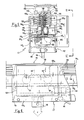
- figure 3 is a lateral elevation view of a trolley of the system runway,
- figure 4 is a transverse sectional view taken along the line IV-IV of figure 3,
- figure 5 is a schematic transverse sectional view, similar to figure 4, which illustrates a preferred embodiment of the conveyor system,
- figure 6 is a lateral elevation view taken along the direction of the arrows VI-VI of figure 5,
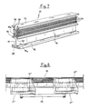
- figure 7 is a perspective view of a portion of the rail of the system of figure 5,
- figure 8 is a lateral elevation view, similar to figure 6, which illustrates one mode of application with paired contiguous trolleys.
- With reference to the diagram of figure 1, the
reference numeral 10 indicates the armature, which is constituted by the conveyor system runway itself, and 11 indicates the inductor, which is constituted by a magnetizable core M rigidly associated with each individual trolley of the conveyor; the armature and the inductor are separated by an air gap "t". - The
armature 10 comprises aferromagnetic portion 12 which coincides with the rail of the runway or with a part thereof, and aplate 13 made of conducting non-magnetic material, advantageously aluminum, stably coupled to theportion 12. The magnetic core M of theinductor 11 is provided with theexciter windings 14, which are advantageously of the three-phase type and are accommodated in a per se known manner in respective recesses (not illustrated) which define corresponding polar expansions (also not illustrated) of the core which are arranged facing thearmature 10; the excitation current is fed to thewindings 14 by means of sliding contacts which will be described hereafter. - In the alternative arrangement of the diagram of figure 2, the
armature 10a is constituted by the core which is rigidly associated with each individual trolley and theinductor 11a is constituted by the rail orrail portion 12a of the runway. Theexciter windings 14a are consequently accommodated in corresponding recesses of the rail, and the core of each individual trolley is provided with a correspondingnon-magnetic plate 13a. - With reference now to figure 3, VC indicates the runway of a conveyor; said runway is constituted by a
overhead rail 20 made of stamped plate with a double T-profile defined by two horizontal wings connected by at least one vertical rib and is provided with aferromagnetic plate 21 and with anon-magnetic plate 22 which are superimposed and connected in a pack-like manner to said rail. A plurality of trolleys CT is suspended from the runway and is intended to transport and move generic loads or semi-worked items. Each trolley CT is provided with a pair of freelyrotatable rollers 23 which are supported bycorresponding arms 24 to which the structure of the trolley CT is suspended. The latter bears the magnetic inductor core M which is rigidly coupled tocrosspieces 25 extending between thearms 24; the polar expansions of said core are arranged facing thenon-magnetic plate 22, and said plate and said core are separated by the air gap "t". - The
exciter windings 14 associated with the core M are powered by means of three slidingcontacts 26 which co-operate with corresponding conductingtracks 27a, 27b, 27c which are supported by the vertical rib of therail 20 with adapted insulating supports interposed. Saidtracks 27 can comprise separate portions (of which in fig. 3 portions T₁, T₂ are visible, separated by distance d), these portions being electrically insulated from one another and powered separately with different voltages and/or frequencies, in order to allow corresponding speed and/or acceleration variations for the individual trolleys which move along the different portions of the runway. - Other tracks, advantageously signal and command transfer tracks, can also be arranged on the
rail 20 in addition to the power tracks particularly for feeding the core M with switching signals adapted to activate and deactivate one or more portions of the exciter winding 14 in order to correspondingly vary the traction stress. - In the variated embodiment of figure 5 to 8, the
rail 110 is constituted by a profiled element made of extruded aluminum which is the result of the combination of afirst rail portion 110a and of asecond rail portion 110b which are superimposed and are both substantially double T-shaped. - The
rail 110 is therefore characterized (figure 7) by avertical rib 111, by abase plate 112, by atop plate 113 and byintermediate wings 114 which are orthogonal to therib 111 and separate the first rail portion from the second rail portion. - The
first portion 110a, which is delimited by thebase plate 112 and by theintermediate wings 114, is adapted to contain firstopposite rollers corresponding supports lateral wings 117a 117b of thesuspension elements 117 of each trolley CT. Said suspension elements comprise, besides saidlateral wings 117a, 117b, astiff plate 118 connecting said lateral wings and provided with ahook 119 for the load, andspacers 120 which are arranged so that the configuration of saidsuspension elements 117 is substantially U-shaped to allow the passage of therail 110. - The first suspension and
sliding rollers base plate 112 and are provided with a peripheral ring surface made of non-ferrous material and with rolling bearings with lubrication for life to improve the sliding of the trolleys. - Each trolley is advantageously provided with two pairs of first opposite rollers which are indicated by 115′ and 115˝ in figure 6. Second lateral contrast and
containment rollers opposite supports base plate 112 in order to prevent lateral oscillations of thesuspension elements 117 with respect to therail 110. This allows to minimize the air gap "t" defined between thebase plate 112 and theinductor core 122 which is supported by the connectingplate 118 in a position underlying thebase plate 112; most of all, however, it keeps said air gap constant, since the described suspension system is insensitive to load variations, to any eccentricity thereof and to the inertial forces which act on the trolley. - A
strip 123 of magnetic material, preferably "Fe 37", is also embedded in thebase plate 112 by coextrusion and constitutes the armature of the linear motors which have thecores 122 of each individual trolley as inductors. - The
second rail portion 110b which is delimited by thetop plate 113 and by theintermediate wings 114 is intended to contain the power supply andcontrol conducting bars 124 in a position providing maximum safety but easy access thereto and to receivesupports 125 for suspending therail 110 from the supporting structure. - The conducting
bars 124, which are of the metal-enclosed type, are removably connected to one face or both faces of therib 111 by means ofknown supports 126 which can be snap-coupled incorresponding seats intermediate wings 114 and respectively on thetop plate 113. - The possibility of using one face, the other face or both faces of the
central rib 111 to accommodate the conductingbars 124 is a considerable advantage both in terms of installation and in terms of system modification. -
Sliding contacts bars 124 and are supported by correspondingcurrent collector assemblies 130a, 130b which are supported by one or both of thelateral wings 117a, 117b of thesuspension elements 117 of each trolley. - By virtue of the configuration of the
rail 110, thesupports 125 are arranged at the center of gravity of the entire suspended system and are simply constituted bycrosspieces 131 which are supported bytie rods 132;locking plates 133 co-operate with said crosspieces and are adapted to clamp the wings of thetop plate 113 of therail 110 by virtue of the traction of the tie rods which engage in respective holes of the crosspieces. - The
suspension elements 117 of each trolley are furthermore preferably provided with a braking andparking skid 140 which is supported by the connectingplate 118 and is pushed into engagement contact with the lower face of thebase plate 112 by an electromagnetic actuation (not illustrated) controlled by amanual actuation 141 of the kind with a threaded shaft which engages a threaded seat of the braking skid. - The axial extension of the
core 122 of each trolley is preferably rather small, advantageously not exceeding 1.5 times the center distance between the pairs offirst rollers 115′, 115˝, in order to minimize the flux dispersed at the curves of therail 110 where eachcore 122 arranges itself substantially along the chord of the curve itself. This entails a corresponding containment of the power used for each trolley; this containment can be easily obviated, when higher power is required, by connecting two or more movement andsuspension elements 117′, 117˝ of respective trolleys CT′, CT˝ by means of articulatedrods 145, as clearly illustrated in figure 8. - Where technical features mentioned in any claim are followed by reference signs, those reference signs have been included for the sole purpose of increasing the intelligibility of the claims and accordingly such reference signs do not have any limiting effect on the scope of each element identified by way of example by such reference signs.
Claims (10)
Applications Claiming Priority (4)
| Application Number | Priority Date | Filing Date | Title |
|---|---|---|---|
| IT5341688U | 1988-09-26 | ||
| IT5341688U IT215079Z2 (en) | 1988-09-26 | 1988-09-26 | CONVEYOR SYSTEM FOR HANDLING OF MATERIALS AND SEMI-FINISHED PRODUCTS ELECTRIC INDUCTION CONTRACTING |
| IT5327689U | 1989-07-26 | ||
| IT5327689U IT217157Z2 (en) | 1989-07-26 | 1989-07-26 | CONVEYOR SYSTEM STRUCTURE PARTICULARLY VIA STROKE EXPENDITURE WITH ASYNCHRONOUS LINEAR MOTOR TROLLEYS |
Publications (2)
| Publication Number | Publication Date |
|---|---|
| EP0361340A1 true EP0361340A1 (en) | 1990-04-04 |
| EP0361340B1 EP0361340B1 (en) | 1994-01-19 |
Family
ID=26329559
Family Applications (1)
| Application Number | Title | Priority Date | Filing Date |
|---|---|---|---|
| EP19890117611 Expired - Lifetime EP0361340B1 (en) | 1988-09-26 | 1989-09-23 | Conveyor system for moving materials and semi-worked items |
Country Status (3)
| Country | Link |
|---|---|
| EP (1) | EP0361340B1 (en) |
| DE (1) | DE68912481T2 (en) |
| ES (1) | ES2048256T3 (en) |
Cited By (6)
| Publication number | Priority date | Publication date | Assignee | Title |
|---|---|---|---|---|
| DE10332689A1 (en) * | 2002-12-12 | 2004-06-24 | Grob-Werke Burkhart Grob E.K. | transport device |
| US20130084157A1 (en) * | 2011-09-30 | 2013-04-04 | Ats Automation Tooling Systems Inc. | System and method for providing vacuum to a moving element |
| EP2691319A1 (en) * | 2011-03-31 | 2014-02-05 | ATS Automation Tooling Systems Inc. | Pallet-based position adjustment system and method |
| IT201900017438A1 (en) * | 2019-09-27 | 2021-03-27 | Ocm S P A | Transport system |
| WO2021259437A1 (en) * | 2020-06-26 | 2021-12-30 | Ecco Sko A/S | A footwear manufacturing conveyor system |
| EP4129866A4 (en) * | 2020-05-28 | 2024-04-10 | Beijing Jingdong Qianshi Tech Co Ltd | Sorting device |
Citations (4)
| Publication number | Priority date | Publication date | Assignee | Title |
|---|---|---|---|---|
| US3426887A (en) * | 1967-02-27 | 1969-02-11 | Morris Ltd Herbert | Drives for conveyors |
| FR1589474A (en) * | 1968-09-25 | 1970-03-31 | ||
| DE2819541A1 (en) * | 1976-04-28 | 1979-11-08 | Drysys King Conveyors Ltd | CONVEYOR SYSTEM WITH ELECTRIC LINEAR MOTOR |
| EP0197751A2 (en) * | 1985-03-29 | 1986-10-15 | Shinko Electric Co. Ltd. | Linear motor truck apparatus |
-
1989
- 1989-09-23 ES ES89117611T patent/ES2048256T3/en not_active Expired - Lifetime
- 1989-09-23 EP EP19890117611 patent/EP0361340B1/en not_active Expired - Lifetime
- 1989-09-23 DE DE1989612481 patent/DE68912481T2/en not_active Expired - Lifetime
Patent Citations (4)
| Publication number | Priority date | Publication date | Assignee | Title |
|---|---|---|---|---|
| US3426887A (en) * | 1967-02-27 | 1969-02-11 | Morris Ltd Herbert | Drives for conveyors |
| FR1589474A (en) * | 1968-09-25 | 1970-03-31 | ||
| DE2819541A1 (en) * | 1976-04-28 | 1979-11-08 | Drysys King Conveyors Ltd | CONVEYOR SYSTEM WITH ELECTRIC LINEAR MOTOR |
| EP0197751A2 (en) * | 1985-03-29 | 1986-10-15 | Shinko Electric Co. Ltd. | Linear motor truck apparatus |
Cited By (12)
| Publication number | Priority date | Publication date | Assignee | Title |
|---|---|---|---|---|
| DE10332689A1 (en) * | 2002-12-12 | 2004-06-24 | Grob-Werke Burkhart Grob E.K. | transport device |
| EP2691319A1 (en) * | 2011-03-31 | 2014-02-05 | ATS Automation Tooling Systems Inc. | Pallet-based position adjustment system and method |
| EP2691319A4 (en) * | 2011-03-31 | 2015-04-08 | Automation Tooling Syst | Pallet-based position adjustment system and method |
| US20130084157A1 (en) * | 2011-09-30 | 2013-04-04 | Ats Automation Tooling Systems Inc. | System and method for providing vacuum to a moving element |
| US9422121B2 (en) | 2011-09-30 | 2016-08-23 | Ats Automation Tooling Systems Inc. | System for providing vacuum to a moving element |
| US9957116B2 (en) * | 2011-09-30 | 2018-05-01 | Ats Automation Tooling Systems Inc. | Method for providing vacuum to a moving element |
| IT201900017438A1 (en) * | 2019-09-27 | 2021-03-27 | Ocm S P A | Transport system |
| WO2021058799A1 (en) * | 2019-09-27 | 2021-04-01 | Ocm S.P.A. | Conveyor system |
| CN114616194A (en) * | 2019-09-27 | 2022-06-10 | Ocm股份公司 | Conveyor system |
| US11807474B2 (en) * | 2019-09-27 | 2023-11-07 | Material Handling Systems, Inc. | Conveyor system |
| EP4129866A4 (en) * | 2020-05-28 | 2024-04-10 | Beijing Jingdong Qianshi Tech Co Ltd | Sorting device |
| WO2021259437A1 (en) * | 2020-06-26 | 2021-12-30 | Ecco Sko A/S | A footwear manufacturing conveyor system |
Also Published As
| Publication number | Publication date |
|---|---|
| DE68912481T2 (en) | 1994-06-01 |
| ES2048256T3 (en) | 1994-03-16 |
| DE68912481D1 (en) | 1994-03-03 |
| EP0361340B1 (en) | 1994-01-19 |
Similar Documents
| Publication | Publication Date | Title |
|---|---|---|
| US3899979A (en) | Magnetic suspension systems for vehicles | |
| US4055123A (en) | Systems for magnetically supporting a vehicle | |
| JP4846237B2 (en) | Magnetic suspension system | |
| US4793263A (en) | Integrated linear synchronous unipolar motor with controlled permanent magnet bias | |
| US7448327B2 (en) | Suspending, guiding and propelling vehicles using magnetic forces | |
| US6629503B2 (en) | Inductrack configuration | |
| US3884154A (en) | Propulsion arrangement equipped with a linear motor | |
| US3158765A (en) | Magnetic system of transportation | |
| DK167748B1 (en) | Magnetic power system for low-friction transport of loads | |
| WO2008136692A2 (en) | Multi-car cyclic magnetic elevator with gravity linear electric generator/motor | |
| CN111373097B (en) | Permanent magnetic suspension train adopting passive low-frequency electromagnetic stabilization | |
| US3895585A (en) | Two-sided linear induction motor especially for suspended vehicles | |
| US5497038A (en) | Linear motor propulsion drive coil | |
| US4142469A (en) | Magnetic suspension system for railway vehicle with lifting force control | |
| US10604898B2 (en) | Rail-bound maglev train | |
| CN102897054A (en) | Magnetism-propelled, centered and suspended conveying system | |
| US3911828A (en) | Linear-induction motor, e.g. for high-speed magnetic-levitation vehicle | |
| EP0361340A1 (en) | Conveyor system for moving materials and semi-worked items | |
| US4941406A (en) | Magnetic and aerodynamic levitation vehicle | |
| US3837287A (en) | Magnetic suspension utilizing an elongated coil | |
| US5249529A (en) | Self-nulling hybred MAGLEV suspension | |
| US4027597A (en) | Linear induction motor with damping cage | |
| Glatzel et al. | The development of the magnetically suspended transportation system in the federal republic of germany | |
| US5602430A (en) | Superconducting electromagnet arrangement for a magnetic levitation system | |
| JP3327367B2 (en) | Transfer equipment |
Legal Events
| Date | Code | Title | Description |
|---|---|---|---|
| PUAI | Public reference made under article 153(3) epc to a published international application that has entered the european phase |
Free format text: ORIGINAL CODE: 0009012 |
|
| AK | Designated contracting states |
Kind code of ref document: A1 Designated state(s): BE DE ES FR GB IT |
|
| 17P | Request for examination filed |
Effective date: 19901004 |
|
| 17Q | First examination report despatched |
Effective date: 19920309 |
|
| RAP1 | Party data changed (applicant data changed or rights of an application transferred) |
Owner name: FATA AUTOMATION S.P.A. |
|
| GRAA | (expected) grant |
Free format text: ORIGINAL CODE: 0009210 |
|
| AK | Designated contracting states |
Kind code of ref document: B1 Designated state(s): BE DE ES FR GB IT |
|
| REF | Corresponds to: |
Ref document number: 68912481 Country of ref document: DE Date of ref document: 19940303 |
|
| REG | Reference to a national code |
Ref country code: ES Ref legal event code: FG2A Ref document number: 2048256 Country of ref document: ES Kind code of ref document: T3 |
|
| ET | Fr: translation filed | ||
| ITF | It: translation for a ep patent filed |
Owner name: MODIANO & ASSOCIATI S.R.L. |
|
| PLBE | No opposition filed within time limit |
Free format text: ORIGINAL CODE: 0009261 |
|
| STAA | Information on the status of an ep patent application or granted ep patent |
Free format text: STATUS: NO OPPOSITION FILED WITHIN TIME LIMIT |
|
| 26N | No opposition filed | ||
| PGFP | Annual fee paid to national office [announced via postgrant information from national office to epo] |
Ref country code: ES Payment date: 20000821 Year of fee payment: 12 |
|
| PGFP | Annual fee paid to national office [announced via postgrant information from national office to epo] |
Ref country code: FR Payment date: 20000822 Year of fee payment: 12 |
|
| PGFP | Annual fee paid to national office [announced via postgrant information from national office to epo] |
Ref country code: BE Payment date: 20000825 Year of fee payment: 12 |
|
| PGFP | Annual fee paid to national office [announced via postgrant information from national office to epo] |
Ref country code: GB Payment date: 20000920 Year of fee payment: 12 |
|
| PGFP | Annual fee paid to national office [announced via postgrant information from national office to epo] |
Ref country code: DE Payment date: 20001121 Year of fee payment: 12 |
|
| PG25 | Lapsed in a contracting state [announced via postgrant information from national office to epo] |
Ref country code: GB Free format text: LAPSE BECAUSE OF NON-PAYMENT OF DUE FEES Effective date: 20010923 |
|
| PG25 | Lapsed in a contracting state [announced via postgrant information from national office to epo] |
Ref country code: ES Free format text: LAPSE BECAUSE OF NON-PAYMENT OF DUE FEES Effective date: 20010924 |
|
| PG25 | Lapsed in a contracting state [announced via postgrant information from national office to epo] |
Ref country code: BE Free format text: LAPSE BECAUSE OF NON-PAYMENT OF DUE FEES Effective date: 20010930 |
|
| REG | Reference to a national code |
Ref country code: GB Ref legal event code: IF02 |
|
| BERE | Be: lapsed |
Owner name: FATA AUTOMATION S.P.A. Effective date: 20010930 |
|
| PG25 | Lapsed in a contracting state [announced via postgrant information from national office to epo] |
Ref country code: DE Free format text: LAPSE BECAUSE OF NON-PAYMENT OF DUE FEES Effective date: 20020501 |
|
| GBPC | Gb: european patent ceased through non-payment of renewal fee |
Effective date: 20010923 |
|
| PG25 | Lapsed in a contracting state [announced via postgrant information from national office to epo] |
Ref country code: FR Free format text: LAPSE BECAUSE OF NON-PAYMENT OF DUE FEES Effective date: 20020531 |
|
| REG | Reference to a national code |
Ref country code: FR Ref legal event code: ST |
|
| REG | Reference to a national code |
Ref country code: ES Ref legal event code: FD2A Effective date: 20021011 |
|
| PG25 | Lapsed in a contracting state [announced via postgrant information from national office to epo] |
Ref country code: IT Free format text: LAPSE BECAUSE OF NON-PAYMENT OF DUE FEES;WARNING: LAPSES OF ITALIAN PATENTS WITH EFFECTIVE DATE BEFORE 2007 MAY HAVE OCCURRED AT ANY TIME BEFORE 2007. THE CORRECT EFFECTIVE DATE MAY BE DIFFERENT FROM THE ONE RECORDED. Effective date: 20050923 |