EP0361335A2 - Change-speed lever apparatus for use in bicycle - Google Patents
Change-speed lever apparatus for use in bicycle Download PDFInfo
- Publication number
- EP0361335A2 EP0361335A2 EP89117591A EP89117591A EP0361335A2 EP 0361335 A2 EP0361335 A2 EP 0361335A2 EP 89117591 A EP89117591 A EP 89117591A EP 89117591 A EP89117591 A EP 89117591A EP 0361335 A2 EP0361335 A2 EP 0361335A2
- Authority
- EP
- European Patent Office
- Prior art keywords
- lever
- cable
- change
- speed
- pulling
- Prior art date
- Legal status (The legal status is an assumption and is not a legal conclusion. Google has not performed a legal analysis and makes no representation as to the accuracy of the status listed.)
- Granted
Links
Images


Classifications
-
- B—PERFORMING OPERATIONS; TRANSPORTING
- B62—LAND VEHICLES FOR TRAVELLING OTHERWISE THAN ON RAILS
- B62M—RIDER PROPULSION OF WHEELED VEHICLES OR SLEDGES; POWERED PROPULSION OF SLEDGES OR SINGLE-TRACK CYCLES; TRANSMISSIONS SPECIALLY ADAPTED FOR SUCH VEHICLES
- B62M25/00—Actuators for gearing speed-change mechanisms specially adapted for cycles
- B62M25/02—Actuators for gearing speed-change mechanisms specially adapted for cycles with mechanical transmitting systems, e.g. cables, levers
- B62M25/04—Actuators for gearing speed-change mechanisms specially adapted for cycles with mechanical transmitting systems, e.g. cables, levers hand actuated
- B62M25/045—Actuators for gearing speed-change mechanisms specially adapted for cycles with mechanical transmitting systems, e.g. cables, levers hand actuated having single actuating means operating both front and rear derailleur
-
- Y—GENERAL TAGGING OF NEW TECHNOLOGICAL DEVELOPMENTS; GENERAL TAGGING OF CROSS-SECTIONAL TECHNOLOGIES SPANNING OVER SEVERAL SECTIONS OF THE IPC; TECHNICAL SUBJECTS COVERED BY FORMER USPC CROSS-REFERENCE ART COLLECTIONS [XRACs] AND DIGESTS
- Y10—TECHNICAL SUBJECTS COVERED BY FORMER USPC
- Y10T—TECHNICAL SUBJECTS COVERED BY FORMER US CLASSIFICATION
- Y10T74/00—Machine element or mechanism
- Y10T74/15—Intermittent grip type mechanical movement
- Y10T74/1526—Oscillation or reciprocation to intermittent unidirectional motion
- Y10T74/1553—Lever actuator
- Y10T74/1555—Rotary driven element
-
- Y—GENERAL TAGGING OF NEW TECHNOLOGICAL DEVELOPMENTS; GENERAL TAGGING OF CROSS-SECTIONAL TECHNOLOGIES SPANNING OVER SEVERAL SECTIONS OF THE IPC; TECHNICAL SUBJECTS COVERED BY FORMER USPC CROSS-REFERENCE ART COLLECTIONS [XRACs] AND DIGESTS
- Y10—TECHNICAL SUBJECTS COVERED BY FORMER USPC
- Y10T—TECHNICAL SUBJECTS COVERED BY FORMER US CLASSIFICATION
- Y10T74/00—Machine element or mechanism
- Y10T74/15—Intermittent grip type mechanical movement
- Y10T74/1558—Grip units and features
- Y10T74/1577—Gripper mountings, lever
- Y10T74/1581—Multiple acting
-
- Y—GENERAL TAGGING OF NEW TECHNOLOGICAL DEVELOPMENTS; GENERAL TAGGING OF CROSS-SECTIONAL TECHNOLOGIES SPANNING OVER SEVERAL SECTIONS OF THE IPC; TECHNICAL SUBJECTS COVERED BY FORMER USPC CROSS-REFERENCE ART COLLECTIONS [XRACs] AND DIGESTS
- Y10—TECHNICAL SUBJECTS COVERED BY FORMER USPC
- Y10T—TECHNICAL SUBJECTS COVERED BY FORMER US CLASSIFICATION
- Y10T74/00—Machine element or mechanism
- Y10T74/20—Control lever and linkage systems
- Y10T74/20012—Multiple controlled elements
- Y10T74/20018—Transmission control
- Y10T74/20037—Occupant propelled vehicle
- Y10T74/20043—Transmission controlled by flexible cable
-
- Y—GENERAL TAGGING OF NEW TECHNOLOGICAL DEVELOPMENTS; GENERAL TAGGING OF CROSS-SECTIONAL TECHNOLOGIES SPANNING OVER SEVERAL SECTIONS OF THE IPC; TECHNICAL SUBJECTS COVERED BY FORMER USPC CROSS-REFERENCE ART COLLECTIONS [XRACs] AND DIGESTS
- Y10—TECHNICAL SUBJECTS COVERED BY FORMER USPC
- Y10T—TECHNICAL SUBJECTS COVERED BY FORMER US CLASSIFICATION
- Y10T74/00—Machine element or mechanism
- Y10T74/20—Control lever and linkage systems
- Y10T74/20012—Multiple controlled elements
- Y10T74/20018—Transmission control
- Y10T74/20085—Restriction of shift, gear selection, or gear engagement
- Y10T74/20098—Separate actuator to disengage restrictor
-
- Y—GENERAL TAGGING OF NEW TECHNOLOGICAL DEVELOPMENTS; GENERAL TAGGING OF CROSS-SECTIONAL TECHNOLOGIES SPANNING OVER SEVERAL SECTIONS OF THE IPC; TECHNICAL SUBJECTS COVERED BY FORMER USPC CROSS-REFERENCE ART COLLECTIONS [XRACs] AND DIGESTS
- Y10—TECHNICAL SUBJECTS COVERED BY FORMER USPC
- Y10T—TECHNICAL SUBJECTS COVERED BY FORMER US CLASSIFICATION
- Y10T74/00—Machine element or mechanism
- Y10T74/20—Control lever and linkage systems
- Y10T74/20207—Multiple controlling elements for single controlled element
- Y10T74/20256—Steering and controls assemblies
- Y10T74/20268—Reciprocating control elements
- Y10T74/2028—Handle bar type
- Y10T74/20287—Flexible control element
-
- Y—GENERAL TAGGING OF NEW TECHNOLOGICAL DEVELOPMENTS; GENERAL TAGGING OF CROSS-SECTIONAL TECHNOLOGIES SPANNING OVER SEVERAL SECTIONS OF THE IPC; TECHNICAL SUBJECTS COVERED BY FORMER USPC CROSS-REFERENCE ART COLLECTIONS [XRACs] AND DIGESTS
- Y10—TECHNICAL SUBJECTS COVERED BY FORMER USPC
- Y10T—TECHNICAL SUBJECTS COVERED BY FORMER US CLASSIFICATION
- Y10T74/00—Machine element or mechanism
- Y10T74/20—Control lever and linkage systems
- Y10T74/20396—Hand operated
- Y10T74/20402—Flexible transmitter [e.g., Bowden cable]
- Y10T74/2042—Flexible transmitter [e.g., Bowden cable] and hand operator
- Y10T74/20438—Single rotatable lever [e.g., for bicycle brake or derailleur]
Definitions
- the change-speed lever apparatus is attached adjacent a grip portion of a steering handle bar of the bicycle and if the apparatus is to provide as many as five or six different speeds, the lever of the apparatus necessarily has a considerable operation stroke.
- the cyclist needs to use two of his fingers, i.e. the thumb and index finger for a forward and reverse operation of the lever, respectively.
- the index finger constributes significantly to the handle gripping condition. Then, if this index finger has to move significantly away from the grip for a change-speed operation as described above, this results in deterioration in the handle gripping condition, thereby to endanger the cyclist.
- the primary object of the present invention is to provide such a change-speed lever apparatus for use in a bicycle as permits a cyclist to carry out a change-speed operation in a safe manner without losing much of his handle gripping force and also in a carefree manner without requiring much attention from the cyclist to the direction of the operation.
- control portions are located adjacent each other for easy lever operations and at the same time the existence of the release control portion will not interfere with the operation of the cable-pulling lever having a significantly long operational stroke.
- the first shaft 11 defines, at a leading end of its outer periphery, a plurality of concave portions 14 and a screw groove engageable with a nut 15.
- the first shaft 11 undetachably supports the winding member 20 and the cable-pulling lever 60.
- a spring 21 for urging the winding member 20 in the rewinding direction.
- Reference numeral 17 denotes a bowl-shaped cover for covering base ends of the winding member 20, the cable-pulling lever 60 and of the release lever 70.
- This mechanism includes a plate-shaped position setting member 19 having an upwardly projecting, setting portion 19a, the setting member 19 being unrotatably fitted on the first shaft 11 via the concave portion 14.
- the setting portion 19a of the position setting member 19 is formed by a bent portion of the position setting member 19.
- the first engaging member 73 and the claws of the positioning member 30 are inclined relative to the radial direction of the winding member 20. Accordingly, when the winding member 20 is pivoted in the winding direction, the first engaging portions 31 and the first engaging member 73 are freely engageable and disengageable with and from each other. On the other hand, when the winding member 20 is pivoted in the rewinding direction, the first engaging portion 31 and the first engaging member 73 become engaged to restrict a pivotal motion of the winding member 20 thereby to maintain the present position of the winding member 20. Incidentally, when the winding member 20 is pivoted in the winding direction, the release lever 70 is pivoted with the engagement and disengagement between the first engaging portion 31 and the first engaging member 73.
- the cable-pulling lever 60 is pivoted in the reverse direction (clockwise in Fig. 2) by the urging force of the spring 63 and is returned to and stopped at its home position through contact between the contact portion 64 and the setting portion 19a, as illustrated in Fig. 6. Then, the cable-pulling lever 60 becomes ready for a next change-speed operation.
- the release lever 70 When the cyclist stops pushing the release lever control portion 71, the release lever 70 is pivoted reversely by the urging force of the release lever spring 72, and the engaging projection 75 again pushes the extention portion 83 thereby to release the engagement between the second engaging member 81 and the second engaging portion 42.
- the winding member 20 as well as the positioning member 30 is reversely pivoted a little further by the urging force of the rewinding spring 21, and the first engaging member 73 becomes engaged with one of the first engaging portions 31 which corresponds to one speed higher position. As this engagement prevents a reverse pivotal motion of the winding member 20 by the rewinding spring 21, this higher speed position can be maintained reliably.
Landscapes
- Engineering & Computer Science (AREA)
- Chemical & Material Sciences (AREA)
- Combustion & Propulsion (AREA)
- Transportation (AREA)
- Mechanical Engineering (AREA)
- Steering Devices For Bicycles And Motorcycles (AREA)
- Mechanical Control Devices (AREA)
Abstract
Description
- The present invention relates to a change-speed lever apparatus for use in a bicycle.
- A conventional change-speed lever apparatus is known, for example, from a Japanese laid-open patent No. 61-143275. This change-speed lever apparatus includes a winding member for winding up a change-speed control cable, the winding member being held in position by a frictional force, a single change-speed lever for effecting a change-speed operation, a pair of oneway mechanisms consisting of ratchet mechanisms arranged in opposition to each other between the change-speed lever and the winding member, each ratchet mechanism having a projectable/retractable claw, and an urging means for urging the change-speed lever back to an intermediate position between its forward and reverse strokes after the winding member is pivoted in a cable winding or cable rewinding direction by a forward or reverse operation of the change-speed lever.
- With the above-described conventional change-speed lever apparatus, however, the change-speed lever is operated in the two directions. Accordingly, for effecting a change-speed operation, a cyclist must pay much of his attention to the direction of the lever operation. This is undesirable in terms of the cyclist's safety as well as change-speed operation efficiency, because the change-speed device will be operated into an unexpected speed position if the cyclist operates the lever in the wrong direction.
- Further, in case the change-speed lever apparatus is attached adjacent a grip portion of a steering handle bar of the bicycle and if the apparatus is to provide as many as five or six different speeds, the lever of the apparatus necessarily has a considerable operation stroke. This means that the cyclist needs to use two of his fingers, i.e. the thumb and index finger for a forward and reverse operation of the lever, respectively. As is wellknown, the index finger constributes significantly to the handle gripping condition. Then, if this index finger has to move significantly away from the grip for a change-speed operation as described above, this results in deterioration in the handle gripping condition, thereby to endanger the cyclist.
- Moreover, in order to be operated not only by the cyclist's thumb but by the index finger, the change-speed lever must be attached to an upper portion of the steering handle. As a result, for forwardly operating the lever, the cyclist must move his thumb clumsily upwards to the position of the lever, whereby the gripping condition can deteriorate in this case also, though may be less significant than the former case.
- In view of the above-described state of the art, the primary object of the present invention is to provide such a change-speed lever apparatus for use in a bicycle as permits a cyclist to carry out a change-speed operation in a safe manner without losing much of his handle gripping force and also in a carefree manner without requiring much attention from the cyclist to the direction of the operation.
- In order accomplish the above-noted object, according to a change-speed lever apparatus for use in a bicycle relating to the present invention, the apparatus has: a fixed member; a winding member for winding up a change-speed control cable, the winding member being pivotably supported to the fixed member and normally urged in a cable rewinding direction, and a cable-pulling lever for pulling the cable for a change-speed operation as the lever is operated in a first direction against the urging force along the cable rewinding direction thereby to cause the winding member to pivot only in the cable winding direction via a oneway mechanism, the cable-pulling lever being returned to a home position thereof by cable-pulling lever urging means, the improvement comprising: a position maintaining mechanism including a first engaging member and a plurality of first engaging portions stepwisely engageable with the first engaging member to maintain a position of the winding member; and a release lever operable to release the engagement between the first engaging member and the first engaging portion with an operation of the release lever in a second direction thereby to effect a change-speed operation by permitting the winding member to pivot in the cable rewinding direction with the cable rewinding urging force, the release lever being returned to a home position thereof by release lever urging means; the first direction of the cable-pulling lever and the second direction of the release lever at the respective home positions being substantially the same.
- With the above-described features of the present invention, the change-speed lever apparatus essentially consists of the cable-pulling lever and the release lever which levers can be operated at the respective home positions by the cyclist in substantially the same direction for pulling or releasing the change-speed control cable respectively in order to carry out a desired change-speed operation. As a result, the cyclist does not need to pay much attention to the direction of the lever operation. Further, since it is much easier for the cyclist to distinguish between the cable-pulling lever and the release lever than to distinguish between two opposite directions of a single change-speed lever, the possibility of erroneous change-speed operation can be minimized. Consequently, with the change-speed lever apparatus of the present invention, a cyclist can carry out a change-speed operation in a reliable, speedy and safe manner without having to pay much attention to the change-speed lever operation per se.
- Moreover, since the cable can be pulled or released by the two levers at their home positions in substantially the same one direction, it has become possible to reduce the operational stroke of the change-speed lever apparatus to approximately a half of that of the conventional apparatus.
- To the above-described construction, it is conceivable to additionally provide a limiting mechanism for limiting an amount of the pivotal motion of the winding member in the cable rewinding direction effected with an operation of the release lever to a predetermined amount.
- With the addition of this limiting mechanism, the position of the winding member to be maintained can be freely set in both of the cable winding and cable rewinding directions.
- Further, according to one preferred embodiment of the present invention, in a change-speed lever apparatus for use in a bicycle, the apparatus has: a fixed member; a cable-pulling lever having a cable-pulling control portion and adapted for pulling and maintaining a change-speed control cable for a change-speed operation as the cable-pulling control portion is operated in a first direction, the cable-pulling lever being returned to a home position thereof after completion of the lever operation in the first direction, the change-speed apparatus comprising: a release lever having a release control portion and operable to release the cable-pulling condition with an operation of the release control portion in a second direction, the release lever being returned to a home position thereof after completion of the lever operation in the second direction; the first direction of the cable-pulling lever and the second direction of the release lever at the respective home positions being substantially the same; when the cable-pulling lever and the release lever are rested at the respective home positions thereof, the cable-pulling control portion and the release control portion being located at different positions in a direction normal to the first and second directions and at the same time being located adjacent each other.
- According to the apparatus having the above-described features, the cable-pulling control portion and the release control portion are not overlapped with each other in the common operating direction, and also these control portions are located adjacent each other. As a result, the cyclist can effect a change-speed operation more easily without having to move his operating finger significantly. Consequently, change speed operations can be effected further speedily and more accurately and the cyclist's handle grippig condition will be further improved.
- If the change-speed lever apparatus having the above-described features is attached to the vicinity of the grip portion of the steering handle, it is also conceivable to dispose the cable-pulling control portion and the release control portion, at the home positions, side by side along the longitudinal direction of the grip portion.
- With such positional arrangement, the cyclist can operate smoothly and easily both of the cable-pulling control portion and the release control portion, i.e. the cable-pulling lever and the release lever only by slightly moving his operating finger along the longitudinal direction of the grip portion in a very natural manner.
- It is further conceivable to dispose the release control portion more distant from the grip portion than the cable-pulling control portion is.
- With the above arrangements of the cable-pulling control portion and the release control portion, the control portions are located adjacent each other for easy lever operations and at the same time the existence of the release control portion will not interfere with the operation of the cable-pulling lever having a significantly long operational stroke.
- Consequently, the present invention has achieved such a change-speed lever apparatus for use in a bicycle as permits a cyclist to carry out a change-speed operation in a safe manner without losing much of his handle gripping force and also in a carefree manner without requiring much attention from the cyclist to the direction of the lever operation.
- Further and other objects, features and effects of the invention will become apparent from the following more detailed description of the embodiments of the invention with reference to the accompanying drawings.
- Accompanying drawings Figs. 1 through 9 illustrate preferred embodiments of the present invention; in which,
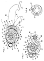
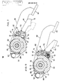
- Fig. 1 is a partially cutaway vertical section showing one preferred embodiment of a change-speed lever apparatus related to the invention,
- Fig. 2 is a cross sectional view,
- Fig. 3 is a cross section similar to Fig. 2, with a portion being cut away,
- Fig. 4 is a section view showing a winding member alone,
- Figs. 5 through 7 are views illustrating operational conditions of the apparatus,
- Fig. 8 is a perspective view showing the apparatus being attached to a bicycle, and
- Fig. 9 is a view illustrating a further embodiment of the invention.
- Preferred embodiments of the present invention will be particularly described hereinafter with reference to the accompanying drawings.
- Fig. 8 is a perspective view showing a change-speed lever apparatus 1 relating to the invention being attached to a steering handle bar 2 of a bicycle. This change-speed lever apparatus 1 is designed for use mainly with a five to six speed rear derailleur.
- The steering handle bar 2 consists of a hollow steel tube having a
grip portion 3 covered with a grip member made of a resin material. A center axis of the handle 2 at thisgrip portion 3 extends substantially normal to a travelling direction of the bicycle and parallel with a horizontal plane. When a cyclist grips thegrip portion 3 of this steering handle 2 in a normal condition, the inter-digital pads of the cyclist's hand contact an upper face of thegrip 3 whereas his thumb is positioned under the handle 2. - This change-speed lever apparatus 1 essentially consists of a cable-pulling
lever 60 and arelease lever 70. In Fig. 8, theselevers control portion 61 of the cable-pullinglever 60 is pushed from the home position in a direction denoted by an arrow in Fig. 8, a windingmember 20 is pivoted in a cable winding direction (to be referred to briefly as a winding direction hereinafter), a change-speed control cable is pulled by a predetermined amount and maintained at this position. On the other hand, if acontrol portion 71 of therelease lever 70 is pushed for a small amount in substantially the same direction as thecontrol portion 61, the windingmember 20 is reversely pivoted in a cable rewinding direction (to be referred to briefly as a rewinding direction hereinafter), the previously wound cable is rewound by a predetermined amount. - Though not shown, the rear derailleur effects a change-speed operation by pivoting a chain guide via a quadrople link mechanism relative to a member fixed to the bicycle body. Also, in this rear derailleur, the chain guide is normally positioned at a high speed sprocket by means of an urging force of a derailleur spring attached to the quadrople link mechanism. Thus, for effecting a change-speed operation to a lower speed position, the link mechanism is pulled via the change-speed control cable against the urging force of the derailleur spring.
- In this particular embodiment, the change-speed lever apparatus 1 is attached to a lower portion of the steering handle 2 adjacent the
grip portion 3. Further, the cable-pulling lever 60 and therelease lever 70 are so arranged as to extend under thegrip portion 3. With this arrangement, both the cable-pulling lever 60 and therelease lever 70 can be operated for a cable pulling or releasing operation by only a thumb of the cyclist' hand as gripping thegrip portion 3. Afirst shaft 11, which constitutes the pivotal axis of the cable-pulling lever 60, and asecond shaft 16, which constitutes the pivotal axis of therelease lever 70, are so oriented as to extend substantially normal to the longitudinal axis of the steering handle 2 adjacent thegrip portion 3 and at the same time in substantially parallel with each other. With this arrangement, both of the above cable pulling and releasing operations by thelevers control portion 61 for a cable pulling operation or thecontrol portion 71 for a cable releasing operation. Accordingly, the cyclist can safely and readily operate this change-speed lever apparatus 1 without significantly destroying his handle gripping hand loop formed by the thumb and the other fingers of his hand as gipping thegrip portion 3. Further, since both the cable-pulling lever 60 and therelease lever 70 are operated in substantially the same direction, the cyclist has to pay little attention to the operational direction of the lever apparatus. At the respective home positions, the cable-pulling lever 60 and therelease lever 70 are positioned adjacent to each other along the longitudinal direction of thegrip portion 3, with thecontrol portion 71 of the latter being positioned more distant from thegrip portion 3 than thecontrol portion 61 of the former is. With this additional arrangement, thecontrol portion 71 of therelease lever 70 can be easily operated with a top end of the cyclist's thumb, and futher a change-speed operation skipping over a plurality of speed positions at one time is readily possible since thecontrol portion 61 can be operated for a long stroke only with a slight movement of the cyclist's thumb toward the terminal end of thegrip portion 3. - Referring now to Fig. 1, the change-speed lever apparatus 1 includes a fixed
member 10 consisting of abase element 12 to be attached to the steering handle 2 and thefirst shaft 11 fastened to theelement 12 by means of ascrew 13. Thebase element 12 is formed integrally with a bracket of a brake lever device 4 (Fig. 8) secured to the steering handle 2. And, thisbase element 12, as shown again in Fig. 8, includes a plate member having a hole engageable with thescrew 13 and a further plate member having a through hole communicating with the hole and a further hole engageable with thesecond shaft 16 which pivotably supports therelease lever 70. - Between the
first shaft 11 and thebase element 12, there are provided a plurality of engaging projections and engaging recesses, through a selective engagement between which thefirst shaft 11 is positionally adjustable relative to thebase element 12 in the peripheral direction of theshaft 11. Thefirst shaft 11 defines, at a leading end of its outer periphery, a plurality ofconcave portions 14 and a screw groove engageable with anut 15. Through this engagement between the groove and thenut 15, thefirst shaft 11 undetachably supports the windingmember 20 and the cable-pullinglever 60. Further, between a base end of thisfirst shaft 11 and the windingmember 20, there is interposed aspring 21 for urging the windingmember 20 in the rewinding direction.Reference numeral 17 denotes a bowl-shaped cover for covering base ends of the windingmember 20, the cable-pullinglever 60 and of therelease lever 70. - Referring now to Figs. 1 and 4, the winding
member 20 comprises a cylindrical structure having a cable-stopper portion 22 at one lateral side thereof. Further, at an intermediate portion in the outer periphery of the windingmember 20, there is defined a cable-guidinggroove 23 extending continuously with thestopper portion 22 and in the peripheral direction of the windingmember 20. At one end of the outer periphery of the windingmember 20 toward the first shaft, there are provided a pair of engagingportions engaging portions first shaft 11. Further, the upper engagingportion 20a unrotatably connects asemicircular positioning member 30 to be described later while the lowerengaging portion 20b unrotatably connects a circular restricting member 40 (will be described later also), respectively relative to the windingmember 20. - The cable-pulling
lever 60 is formed of a metal plate and includes, at free end thereof, thecontrol portion 61 which is despressed by a cyclist's thumb for pulling the change-speed control cable. And, thislever 60 is pivotably supported to thefirst shaft 11 via afirst shaft hole 62. On the other hand, above this cable-pullinglever 60, thefirst shaft 11 unrotatably supports, via theconcave portion 14, aspring receiver plate 18 having astopper portion 18a for stopping one end of a cable-pullinglever spring 63, whereas the other end of thisspring 63 is secured to the cable-pullinglever 60, whereby the cable-pullinglever 60 is normally urged against the direction for cable pulling operation. - For setting a home position of the above-described cable-pulling
lever 60, there is provided a mechanism illustrated in Figs. 1 through 3, 5 and 6. This mechanism includes a plate-shapedposition setting member 19 having an upwardly projecting, settingportion 19a, the settingmember 19 being unrotatably fitted on thefirst shaft 11 via theconcave portion 14. In operation, as this settingmember 19 is brought into contact with acontact portion 64 of the cable-pullinglever 60 urged by thespring 63, thelever 60 is stopped at its home position. Incidentally, the settingportion 19a of theposition setting member 19 is formed by a bent portion of theposition setting member 19. - A oneway mechanism W for permitting the pivotal movement of the winding
member 20 only in the winding direction, as illustrated in Figs. 1 through 3, 5 and 6, is disposed between the restrictingmember 40 rotatable in unison with the windingmember 20 and the cable-pullinglever 60. This oneway mechanism W includes a claw-shaped transmittingelement 51 pivotably fitted on an end portion of the cable-pullinglever 60, aclaw spring 52 for unidirectionally urging the transmittingelement 51 and a plurality of transmittedportions 41 dispersed with a predetermined peripheral distance in a part of the outer periphery of the restrictingmeber 40. Further, thespring receiver plate 18 includes a projection of arelease cam 18b for releasing the engagement between the transmittingelement 51 and the transmittedportion 41 when the cable-pullinglever 60 has returned to its home position. - The
release control lever 70, as shown in Figs. 1 and 2, is formed of a metal plate and includes, at free end thereof, thecontrol portion 71 which is despressed by the cyclist's thumb for releasing the change-speed control cable from the pulled condition. Thisrelease lever 70 is pivotably supported via its base end to thesecond shaft 16. Further, between the base element and thislever 70, there is interposed arelease lever spring 72 for urging therelease lever 70 against the release operation direction. - Next, a position maintaining mechanism P will be described with reference to Figs. 2, 5 and 6. This position maintaining mechanism P essentially includes first engaging
portions 31 consisting of a plurality of recesses defined in the positioningmember 30 and a claw-shaped first engagingmember 73 projected from the base end of therelease lever 70. That is to say, therelease lever 70 acts not only for the position maintaining function of this position maintaining mechanism P but for releasing this mechanism P. The first engagingmember 73 is provided adjacent the first engagingportions 31 by the urging force of therelease lever spring 72. Further, the first engagingportions 31 are formed by a plurality of claws peripherally dispersed with a predetermined distance about the positioningmember 30. The first engagingmember 73 and the claws of the positioningmember 30 are inclined relative to the radial direction of the windingmember 20. Accordingly, when the windingmember 20 is pivoted in the winding direction, the first engagingportions 31 and the first engagingmember 73 are freely engageable and disengageable with and from each other. On the other hand, when the windingmember 20 is pivoted in the rewinding direction, the first engagingportion 31 and the first engagingmember 73 become engaged to restrict a pivotal motion of the windingmember 20 thereby to maintain the present position of the windingmember 20. Incidentally, when the windingmember 20 is pivoted in the winding direction, therelease lever 70 is pivoted with the engagement and disengagement between the first engagingportion 31 and the first engagingmember 73. - The home position of the
release lever 70 is determined through contact between the first engagingmember 73 and abottom portion 32 of the first engagingportion 31. Further, in order to restrict the release operation stroke of therelease lever 70, at a side end of the base end of therelease lever 70 opposite to the first engagingmember 73, there is provided acontact portion 74 which comes into contact with the outer periphery of the positioningmember 30. Also, in order to avoid interference between the releaselever control portion 71 and the cable-pullinglever control portion 61, thecontrol portion 71 at its home position is so disposed as to slightly project before thecontrol portion 61 at its home position. - Between the restricting
member 40 and thesecond shaft 16, there is provided a limiting mechanism L for limiting an amount of the winding-direction-wise pivotal movement of the windingmember 20 effected with an operation of therelease lever 70 to one pitch amount of the first engagingportions 31. In this limiting mechanism L, as illustrated in Figs. 1 through 3, 5 and 6, the restrictingmember 40 includes, at its peripheral portion opposite to the transmittedportion 41, a pluarlity of secondengaging portions 42 consisting of concave portions. On the other hand, thesecond shaft 16 pivotably mounts a restrictingclaw member 80 having a claw-shaped second engagingmember 81 selectively engageable with the secondengaging portions 42. Further, the second engagingmember 81 is urged toward the secondengaging portions 42 by means of a restrictingspring 62. With these arrangements, the amount of winding-direction-wise pivotal motion of the windingmember 20 is limited. More particularly, the first engagingmember 73 and the second engagingmember 81 are so arranged that the second engagingmember 81 is positioned at a projection between an adjacent pair of the secondengaging portions 42 when the first engagingmember 73 is engaged with the first engagingportion 31. The restrictingclaw member 80 includes, at a side opposite to the second engagingmember 81, anextention portion 83. On the other hand, therelease lever 70 includes, at a lower side thereof, an engagingporjection 75 which comes into contact with theextention portion 83 so as to release the engagement between the second engagingmember 81 and the second engagingportion 42. With these, when therelease lever 70 is pivoted, the amount of winding-direction-wise pivotal motion of the windingmember 20 can be limited within one pitch amount of the first engagingportions 31. - Next, operational functions of the change-speed lever apparatus having the above-described construction will be particularly described.
- Figs. 1 and 2 show the apparatus being set at a highest speed position. In this, the cable-pulling
lever 60 is rested at its home position by the urging force of thespring 63 and also by the contact between thecontact portion 64 and the settingportion 19a of theposition setting member 19. Further, the transmittingelement 51 has its leading end contacting therelease portion 18b of thespring receiver plate 18. On the other hand, therelease lever 70 is rested at its home position by the contact between the first engagingmember 73 and thebottom portion 32 of the first engagingportion 31. - First, a change-speed operation into a lower speed position from the above highest speed position of Figs. 1 and 2 will be described.
- When the cyclist places the thumb of his handle-gripping hand into contact with the
control portion 61 of the cable-pullinglever 60 and then pivots this counterclockwise in the tangential direction in Fig. 2, as illustrated in Fig. 5, the transmittingelement 51 comes into engagement with one of the transmittedportions 41 of the restrictingmember 40, thereby to permit the manual forward force applied to thelever 60 to be transmitted via the restrictingmember 40 to the windingmember 20. With this, the windingmember 20 is pivoted in the winding direction to pull the change-speed control cable. In this operation, if the stroke of the forward pivotal motion of the cable-pullinglever 60 reaches one pitch of the first engagingportions 31, the change-speed operation is effected for one speed stage. Whereas, if the stroke reaches two pitches of the same, the change-speed operation is effected for two speed stages. In this way, with a single thumb operation, the change-speed operation is possible step-by-step or skipping over a plurality of positions at one time up to the maximum of three positions. For effecting a change-speed operation over four speed positions, the cable-pullinglever 60 is once returned to its home position and then pivoted in the forward direction again. Thereafter, the change-speed operation is possible step-by-step or skipping over a plurality of positions at one time. - When the desired lower speed position is realized, as shown in Fig.6, the first engaging
member 73 is engaged with one first engagingportion 31 corresponding to the lower speed position, thereby to prevent a return motion of the windingmember 20. As a result, this lower speed position can be maintained reliably. - After the completion of the above-described change speed operation, if the cyclist releases his thumb from the
control portion 61, the cable-pullinglever 60 is pivoted in the reverse direction (clockwise in Fig. 2) by the urging force of thespring 63 and is returned to and stopped at its home position through contact between thecontact portion 64 and the settingportion 19a, as illustrated in Fig. 6. Then, the cable-pullinglever 60 becomes ready for a next change-speed operation. - As described above, if the change-speed lever apparatus of the present invention is used for providing five to six different speeds, a change-speed operation from a high speed position to a lower speed position can be carried out smoothly by horizontally pushing the cable-pulling
lever 60 with the thumb for two times. - Next, a change-speed operation from the low speed position of Fig. 6 back to a higher speed position will be described.
- As shown in Fig. 6, if the cyclist pushes the
release lever 70 rested at its home position in the release direction which is substantially parallel with the operational direction of the cable-pullinglever 60, the first engagingmember 73 of therelease lever 70 moves away from the first engagingportion 31 of theposition maintaining member 30, thereby to release the windingmember 20 from the position-maintained condition. Then, this released windingmember 20 is reversely pivoted in the rewinding direction by the urging force of the rewindingspring 21. In the course of this operation, the engagement between theextension portion 83 of the restrictingclaw member 80 and the engagingprojection 75 of thereleae lever 70 is also released. Thus, as shown in Fig. 7, the second engagingmember 81 urged by the restrictingspring 82 comes into engagement with one of the secondengaging portions 42 of the restrictingmember 40, thereby to limit the amount of the return movement of the winding member effected by the rewindingspring 21 within one pitch of the first engagingportion 31. - When the cyclist stops pushing the release
lever control portion 71, therelease lever 70 is pivoted reversely by the urging force of therelease lever spring 72, and the engagingprojection 75 again pushes theextention portion 83 thereby to release the engagement between the second engagingmember 81 and the second engagingportion 42. At the same time, the windingmember 20 as well as the positioningmember 30 is reversely pivoted a little further by the urging force of the rewindingspring 21, and the first engagingmember 73 becomes engaged with one of the first engagingportions 31 which corresponds to one speed higher position. As this engagement prevents a reverse pivotal motion of the windingmember 20 by the rewindingspring 21, this higher speed position can be maintained reliably. - Thus returned
release lever 70 is rested at its home position through the contact between thebottom portion 32 of the first engagingportion 31 and the first engagingmember 73, as illustrated in Fig. 6. Then, therelease lever 70 is ready for a next release operation. Thereafter, if thisrelease lever 70 at its home position is again pivoted, in the same manner as described above, the engagement between the first engagingmember 73 and the first engagingportion 31 is released, and the windingmember 20 is pivoted reversely by the force of the rewindingspring 21 to release the change-speed control cable for effecting a change-speed operation into one step higher speed position. - Some alternate embodiments of the invention will be specifically described next.
- I. In the foregoing embodiment, the reverse pivotal motion of the winding
member 20 is realized by the urging force of the rewindingspring 21. In place of this, the windingmember 20 can be pivoted reversely, for example, by the urging force of the derailleur spring attached to the derailleur. That is, the rewindingspring 21 disposed between the windingmember 20 and thespring receiver 18 of the fixedmember 10 is not essential for the lever apparatus of the present invention. - II. The
release lever 70 can be attached to another place than to thebase member 12, for example, to theposition setting member 19 or to thespring receiver plate 18. - III. In the foregoing embodiment, the positioning
member 30 and the restrictingmember 40 are provided as entities separate from the windingmember 20. Instead, thesemembers member 20. - IV. The first engaging
member 73 of the position maintaining mechanism P can be formed by other than the claw member projecting from therelease lever 70. For instance, as illustrated in Fig. 9, aball 91 can be used as this first engagingmember 73. In this case, between thisball 91 and therelease lever 70, aspring receiver 93 supports an urgingspring 92 for urging theball 91 toward the first engagingportions 31. And, theball 91, the urgingspring 92 and thespring receiver 93 are attached to the fixedmember 10 by means of asupport element 94. With this alternate construction, when theball 91 comes into engagement with the first engagingportion 31, the urgingspring 92 elastically resiles to cause a sharp drop in the load acting on the cable-pullinglever 60, and this sharp drop in the load can provide a clicking feel to the cyclist's hand operating thelever 60 for each change speed operation. As a result, the cyclist can be aware what speed position he has shifted into. In this construction, it is to be noted, therelease lever 70 is stopped at its home position through contact between thelever 70 and acontact portion 95 of thespring receiver 93. - V. In the foregoing embodiment, the first engaging
portions 31 of the position maintaining mechanism P are peripherally dispersed relative to the windingmember 20. Alternately, these first engagingportions 31 can be disposed along the axis of thefirst shaft 11 relative to the windingmember 20. For instance, in the above described case of Fig. 9 where theball 91 is used as the first engagingmember 73, at one end of the windingmember 20 relative to the axis of thefirst shaft 11, there is fixed a circular link plate having a smaller diameter than this windingmember 20, and this circular link plate forms the first engagingportions 31 in its peripery of upper or lower side; whereas, therelease lever 70 is attached to theposition setting member 19 or to thespring receiver plate 18. With this construction, a disadvantageous enlargement of the windingmember 20 can be effectively prevented and the pivot of therelease lever 70 can be located closer to thefirst shaft 11. As a result, the entire change-speed lever apparatus can be formed compact, and the apparatus can be attached still closer to thegrip portion 3, whereby the thumb operations of the cable-pullinglever 60 and therelease lever 70 will be further facilitated. - VI. For effecting a change-speed operation from a low speed position to a higher speed position, the construction of the foregoing embodiment requires a plurality of thumb operations of the
release control lever 70 for a number of times corresponding to the desired number of speed positions to be changed over, because the pivotal amount of the windingmember 20 is limited to one pitch of the first engagingportions 31 by the engagement between the second engagingmember 80 of the restrictingclaw member 80 and the second engagingportion 81. Instead, with elimination of the restrictingclaw member 80 of the limiting mechanism L, it can be arranged so that the amount of engagement betweeen the first engagingmember 73 and the first engagingportion 31 may be controlled according to an operational amount of therelease lever 70 thereby to allow the windingmember 20 to pivot step-by-step or skipping over a plurality of steps for one time. - VII. The setting
portion 19a for setting the home position of the cable-pullinglever 60 can be formed integrally with the fixedmember 10. - VIII. In the foregoing embodiment, the home position of the
release lever 70 is restricted by the contact between thebottom portion 32 of the first engagingportion 31 and the first engagingmember 73. Instead, this home position of therelease lever 70 can be restricted by an integral portion of the fixedmember 10 similar to the settingportion 19a used for restricting the home position of the cable-pullinglever 60. - IX. The
base member 12 can be fixed to the steering handle bar 2 directly or indirectly through a band element. - X. The change-speed lever apparatus of the invention can be used with a front derailleur rather than with the rear derailleur.
- XI. In the foregoing embodiment, the oneway mechanism W includes the claw-shaped transmitting
element 51 and the transmittedportions 41 formed in the outer periphery of the positioningmember 30. Alternately, this oneway mechanism W can be of a friction type. - XII. In the foregoing embodiment, the cable-pulling
lever 60 and the windingmember 20 share thesame pivot shaft 11. Instead, thelever 60 and themember 20 can use separate pivot shafts. - XIII. In the foregoing embodiment, the attaching orientations of the first and
second shafts shafts lever control portion 61 and the releaselever control portion 71 can be most conveniently operated by the thumb or another finger of the cyclist's hand gripping as thegrip portion 3. For instance, thecontrol portions first shaft 11 and thesecond shaft 16 are oriented in parallel with the axis of the steering handle bar 2. - XIV. The extending positions of the cable-pulling
lever 60 and therelease lever 70 may be conveniently adjusted according to the extending direction of thegrip portion 3. For example, when the longitudinal axis of thisgrip portion 3 of the steering handle bar 2 extends along the travelling direction of the bicycle, the inter-digital pads of the cyclist's hand as gripping thegrip portion 3 are located on the outer side face of thegrip portion 3 facing the outside of the bicycle body. In this case, accordingly, the cable-pullinglever 60 and therelease lever 70 are caused to extend from the inner side face of thegrip portion 3 facing the cyclist. - The invention may be embodied in other specific forms without departing from the sprit or essential characteristics thereof. The present embodiments are therefore to be considered in all respects as illustrative and not restrictive, the scope of the invention being indicated by the appended claims rather than by the foregoing description and all changes which come within the meaning and range of equivalency of the claims are therefore intended to be embraced therein.
Claims (19)
a fixed member;
a winding member for winding up a change-speed control cable, the winding member being pivotably supported to the fixed member and normally urged in a cable rewinding direction, and
a cable-pulling lever for pulling the cable for a change-speed operation as the lever is operated in a first direction against the urging force along the cable rewinding direction thereby to cause the winding member to pivot only in the cable winding direction via a oneway mechanism, the cable-pulling lever being returned to a home position thereof by cable-pulling lever urging means, the improvement comprising:
a position maintaining mechanism including a first engaging member and a plurality of first engaging portions stepwisely engageable with the first engaging member to maintain a position of the winding member; and
a release lever operable to release the engagement between the first engaging member and the first engaging portion with an operation of the release lever in a second direction thereby to effect a change-speed operation by permitting the winding member to pivot in the cable rewinding direction with the cable rewinding urging force, the release lever being returned to a home position thereof by release lever urging means;
said first direction of the cable-pulling lever and said second direction of the release lever at said respective home positions being substantially the same.
a limiting mechanism for limiting a pivotal amount of said winding member in the cable rewinding direction effected with an operation of said release lever to a predetermined amount.
a fixed member;
a cable-pulling lever having a cable-pulling control portion and adapted for pulling and maintaining a change-speed control cable for a change-speed operation as the cable-pulling portion is operated in a first direction, the cable-pulling lever being returned to a home position thereof after completion of the lever operation in the first direction, the change-speed apparatus comprising:
a release lever having a release control portion and operable to release the cable-pulling condition with an operation of the release control portion in a second direction, the release lever being returned to a home position thereof after completion of the lever operation in the second direction;
said first direction of the cable-pulling control portion and said second direction of the release control portion at said respective home positions being substantially the same;
when said cable-pulling lever and said release lever are rested at the respective home positions theroef, said cable-pulling control portion and said release control portion being located at different positions in a direction normal to said first and second directions and at the same time being located adjacent each other.
Applications Claiming Priority (4)
| Application Number | Priority Date | Filing Date | Title |
|---|---|---|---|
| JP63239266A JP2730555B2 (en) | 1988-09-24 | 1988-09-24 | Gear lever for bicycle |
| JP239266/88 | 1988-09-24 | ||
| JP11769389A JPH0288385A (en) | 1989-05-10 | 1989-05-10 | Speed change lever device for bicycle |
| JP117693/89 | 1989-05-10 |
Publications (3)
| Publication Number | Publication Date |
|---|---|
| EP0361335A2 true EP0361335A2 (en) | 1990-04-04 |
| EP0361335A3 EP0361335A3 (en) | 1990-12-05 |
| EP0361335B1 EP0361335B1 (en) | 1994-02-16 |
Family
ID=26455765
Family Applications (1)
| Application Number | Title | Priority Date | Filing Date |
|---|---|---|---|
| EP89117591A Expired - Lifetime EP0361335B1 (en) | 1988-09-24 | 1989-09-22 | Change-speed lever apparatus for use in bicycle |
Country Status (3)
| Country | Link |
|---|---|
| US (1) | US5012692A (en) |
| EP (1) | EP0361335B1 (en) |
| DE (1) | DE68913113T2 (en) |
Cited By (18)
| Publication number | Priority date | Publication date | Assignee | Title |
|---|---|---|---|---|
| FR2701917A1 (en) * | 1993-02-26 | 1994-09-02 | Sachs Ind Sa | Device with two control members for a cycle derailleur |
| US5355745A (en) * | 1992-08-12 | 1994-10-18 | Chuan Fei Industrial Limited Company | Bicycle speed controller |
| EP0628475A1 (en) * | 1992-12-28 | 1994-12-14 | Mory Suntour Inc. | Derailleur |
| EP0661205A1 (en) * | 1993-12-28 | 1995-07-05 | Shimano Inc. | Shifting apparatus for a bicycle |
| EP0785128A3 (en) * | 1996-01-19 | 1997-12-10 | Shimano Inc. | Shifting apparatus for bicycles |
| EP0940334A1 (en) * | 1998-03-04 | 1999-09-08 | SRAM Deutschland GmbH | Shifting apparatus for bicycle change-speed device |
| WO2000059774A1 (en) * | 1999-04-03 | 2000-10-12 | Sram Deutschland Gmbh | Change-speed lever for a bicycle gear |
| CN1072582C (en) * | 1996-02-14 | 2001-10-10 | 株式会社岛野 | Combined brake and shifting device |
| EP1024079A3 (en) * | 1999-01-28 | 2002-02-06 | Shimano Inc. | Shifting unit for a bicycle |
| DE10213450A1 (en) * | 2002-03-26 | 2003-10-16 | Sram De Gmbh | Release unit for ratchet mechanism in trigger switch, e.g. twist grips for bicycle gear changes etc. has toothed holder part, is without ratchet toothing to reduce friction, and lever with release element acting with locking element |
| EP1312541A3 (en) * | 2001-11-16 | 2005-06-01 | Campagnolo Srl | Gear-change control device for a bicycle |
| EP1854713A2 (en) | 2006-05-10 | 2007-11-14 | Shimano Inc. | Bicycle shifting mechanism |
| EP2189363A1 (en) | 2008-11-20 | 2010-05-26 | Shimano, Inc. | Cable operating mechanism |
| US8833199B2 (en) | 2006-02-23 | 2014-09-16 | Campagnolo S.R.L. | Bicycle brake control device |
| CN104890804A (en) * | 2014-03-05 | 2015-09-09 | 日驰企业股份有限公司 | Bicycle speed variator |
| US9267536B2 (en) | 2005-06-27 | 2016-02-23 | Campagnolo S.R.L. | Control device for a bicycle derailleur |
| US10118664B2 (en) | 2007-03-01 | 2018-11-06 | Campagnolo S.R.L. | Control device for a bicycle and bicycle comprising such a device |
| EP2842860B1 (en) | 2013-08-26 | 2019-05-15 | SRAM Deutschland GmbH | Holding and release mechanism for holding and releasing a rope pick-up device |
Families Citing this family (62)
| Publication number | Priority date | Publication date | Assignee | Title |
|---|---|---|---|---|
| SE462279B (en) * | 1988-09-29 | 1990-05-28 | Trama Ab | DEVICE FOR CYCLES |
| EP0472739B1 (en) * | 1990-03-09 | 1996-01-31 | Mory Suntour Inc. | Speed change control lever device for bicycle |
| JP2523752Y2 (en) * | 1990-03-26 | 1997-01-29 | マエダ工業株式会社 | Speed change lever device for bicycle |
| JP3065655B2 (en) * | 1990-11-13 | 2000-07-17 | 株式会社シマノ | Speed change device for bicycle |
| JP3065656B2 (en) * | 1990-11-14 | 2000-07-17 | 株式会社シマノ | Speed change device for bicycle |
| JP3245186B2 (en) * | 1991-04-04 | 2002-01-07 | 株式会社シマノ | Speed change device for bicycle |
| JP3245188B2 (en) * | 1991-04-19 | 2002-01-07 | 株式会社シマノ | Speed change device for bicycle |
| US5191807A (en) * | 1991-12-03 | 1993-03-09 | Hsu Yi Hsung | Indexed gear-shift mechanism |
| JP2601207Y2 (en) * | 1992-12-28 | 1999-11-15 | 株式会社シマノ | Speed change device for bicycle |
| JPH06239287A (en) * | 1993-02-12 | 1994-08-30 | Mori San Tsuaa:Kk | Transmission operation device for bicycle |
| JP2606246Y2 (en) * | 1993-06-17 | 2000-10-10 | 株式会社シマノ | Speed change device for bicycle |
| US5361645A (en) * | 1993-08-24 | 1994-11-08 | Industrial Technology Research Institute | Shift lever apparatus for use in bicycle |
| JP3359788B2 (en) * | 1995-06-23 | 2002-12-24 | 株式会社シマノ | Bicycle gear shifting operation sub-lever |
| JP3623020B2 (en) * | 1995-08-09 | 2005-02-23 | 株式会社シマノ | Bicycle shifting operation device |
| US5632226A (en) * | 1995-09-27 | 1997-05-27 | Industrial Technology Resarch Institute | Bicycle speed indicator |
| IT1281313B1 (en) * | 1995-10-19 | 1998-02-17 | Campagnolo Srl | GEAR CONTROL DEVICE FOR A "MOUNTAIN-BIKE" OR SIMILAR TYPE. |
| IT1285834B1 (en) * | 1995-10-19 | 1998-06-24 | Campagnolo Srl | CONTROL DEVICE OF A BICYCLE DERAILLEUR, INCLUDING AN ANTAGONIST SPRING OF THE DERAILLEUR SPRING. |
| US5732593A (en) * | 1996-01-31 | 1998-03-31 | Industrial Technology Research Institute | Bicycle speed changing apparatus |
| US5768945A (en) * | 1996-02-14 | 1998-06-23 | Shimano, Inc. | Extension handle for a bicycle shifting device |
| TW378183B (en) * | 1996-02-14 | 2000-01-01 | Shimano Kk | Bicycle shift levers which surround a handlebar |
| US5682794A (en) * | 1996-06-05 | 1997-11-04 | Shimano, Inc. | Bicycle shifting control unit |
| TW434196B (en) | 1997-06-25 | 2001-05-16 | Ibm | Selective etching of silicate |
| US5965465A (en) * | 1997-09-18 | 1999-10-12 | International Business Machines Corporation | Etching of silicon nitride |
| US6033996A (en) * | 1997-11-13 | 2000-03-07 | International Business Machines Corporation | Process for removing etching residues, etching mask and silicon nitride and/or silicon dioxide |
| US6150282A (en) * | 1997-11-13 | 2000-11-21 | International Business Machines Corporation | Selective removal of etching residues |
| US5957002A (en) * | 1998-05-06 | 1999-09-28 | Industrial Development Bureau | Dual lever type derailleur gear unit for a bicycle |
| US6200891B1 (en) | 1998-08-13 | 2001-03-13 | International Business Machines Corporation | Removal of dielectric oxides |
| US6117796A (en) * | 1998-08-13 | 2000-09-12 | International Business Machines Corporation | Removal of silicon oxide |
| US6450060B1 (en) | 2000-03-17 | 2002-09-17 | Shimano, Inc. | Bicycle shift device having a linearly sliding shift lever operated by a pivoting cover |
| US6397700B1 (en) * | 2000-09-18 | 2002-06-04 | Falcon Industrial Co., Ltd. | Dual dial rod speed changing indicator |
| ITTO20010011A1 (en) * | 2001-01-11 | 2002-07-11 | Campagnolo Srl | INTEGRATED GEARBOX AND BRAKE CONTROL GROUP FOR A BICYCLE. |
| US6862948B1 (en) | 2001-10-18 | 2005-03-08 | John L. Calendrille, Jr. | Shifter for a bicycle using a dual action lever which moves in the same motion as the natural movement of the thumb |
| DE10205278B4 (en) * | 2002-02-08 | 2019-03-14 | Sram Deutschland Gmbh | release mechanism |
| DE10224196A1 (en) | 2002-05-31 | 2003-12-11 | Sram De Gmbh | Cable retraction mechanism for trigger switches |
| US7152497B2 (en) * | 2003-01-27 | 2006-12-26 | Shimano, Inc. | Method and apparatus for shifting a bicycle transmission by multiple steps |
| US7194928B2 (en) * | 2003-05-30 | 2007-03-27 | Shimano Inc. | Bicycle shift operating device |
| EP1564131B1 (en) * | 2004-02-06 | 2007-08-15 | Campagnolo S.R.L. | Actuation device for a control cable for a bicycle gearshift |
| DE102004014035A1 (en) * | 2004-03-19 | 2005-10-06 | Sram Deutschland Gmbh | Bicycle gearshift device |
| US7882763B2 (en) * | 2004-07-23 | 2011-02-08 | Shimano, Inc. | Shift control device for a bicycle transmission |
| US7437969B2 (en) * | 2004-09-29 | 2008-10-21 | Shimano Inc. | Bicycle shift operating device |
| US8549954B2 (en) | 2004-09-30 | 2013-10-08 | Shimano, Inc. | Bicycle shift device having a linearly sliding shift lever operated by a pivoting interface member |
| US8181553B2 (en) * | 2004-10-25 | 2012-05-22 | Shimano Inc. | Position control mechanism for bicycle control device |
| US7367420B1 (en) | 2004-12-13 | 2008-05-06 | Polaris Industries Inc. | All terrain vehicle (ATV) having a rider interface for electronic or mechanical shifting |
| US7779718B2 (en) * | 2005-03-03 | 2010-08-24 | Sram, Llc | Bicycle shifter |
| US7802489B2 (en) * | 2005-06-01 | 2010-09-28 | Shimano Inc. | Bicycle control device |
| JP5027999B2 (en) * | 2005-07-08 | 2012-09-19 | キヤノン株式会社 | Recording apparatus and control method thereof |
| US20070068312A1 (en) * | 2005-09-07 | 2007-03-29 | Shimano Inc. | Bicycle shift control mechanism |
| US9797434B2 (en) * | 2005-09-14 | 2017-10-24 | Shimano, Inc. | Bicycle shift operating device with a multi-direction operating member |
| JP4078369B2 (en) * | 2005-10-06 | 2008-04-23 | 株式会社シマノ | Bicycle shifting operation device |
| DE202006008605U1 (en) * | 2005-12-01 | 2006-10-26 | Shimano Inc., Sakai | Bicycle movement controlling unit, has two levers independent of each other, where one lever can be actuated from starting position to control position by exertion of pressure on one of the actuation areas of respective lever |
| ATE477997T1 (en) | 2006-01-23 | 2010-09-15 | Campagnolo Srl | CONTROL DEVICE FOR BICYCLE CHAIN GEARS |
| US7665383B2 (en) * | 2006-01-31 | 2010-02-23 | Shimano Inc. | Bicycle shift control device |
| US8777788B2 (en) * | 2007-02-08 | 2014-07-15 | Shimano Inc. | Bicycle component positioning device |
| ITMI20070239A1 (en) * | 2007-02-09 | 2008-08-10 | Campagnolo Srl | CONTROL DEVICE FOR A BICYCLE DERAILLEUR |
| US8016705B2 (en) * | 2007-04-19 | 2011-09-13 | Shimano Inc. | Bicycle component positioning device |
| US9334020B2 (en) * | 2007-04-26 | 2016-05-10 | Shimano Inc. | Bicycle component positioning device |
| ITMI20072230A1 (en) * | 2007-11-23 | 2009-05-24 | Campagnolo Srl | CONTROL DEVICE FOR BICYCLE WITH RECURCED HANDLEBAR |
| US10017224B2 (en) * | 2008-01-08 | 2018-07-10 | Shimano Inc. | Bicycle shift operating device |
| US9227689B2 (en) * | 2008-01-08 | 2016-01-05 | Shimano Inc. | Bicycle shift operating device |
| US9056597B2 (en) * | 2011-09-29 | 2015-06-16 | Shimano Inc. | Bicycle control device |
| US9651138B2 (en) | 2011-09-30 | 2017-05-16 | Mtd Products Inc. | Speed control assembly for a self-propelled walk-behind lawn mower |
| JP2015223985A (en) * | 2014-05-29 | 2015-12-14 | 株式会社シマノ | Operation device for bicycle |
Citations (6)
| Publication number | Priority date | Publication date | Assignee | Title |
|---|---|---|---|---|
| GB562420A (en) * | 1943-03-02 | 1944-06-30 | Ariel Motors Ltd | Improvements relating to actuating mechanisms for variable speed gears |
| US3901095A (en) * | 1974-06-17 | 1975-08-26 | Joseph W Wechsler | Bicycle gear shift |
| GB2012893A (en) * | 1978-01-12 | 1979-08-01 | Ti Raleigh Ind Ltd | Improvements in or Relating to Control Means for Elongate Members |
| US4343201A (en) * | 1979-07-16 | 1982-08-10 | Shimano Industrial Company Limited | Speed control device |
| EP0067692A1 (en) * | 1981-06-15 | 1982-12-22 | Shimano Industrial Company Limited | Control device for a two-speed derailleur |
| GB2169065A (en) * | 1984-12-28 | 1986-07-02 | Sturmey Archer Ltd | Indexing mechanisms and controls embodying the same |
Family Cites Families (16)
| Publication number | Priority date | Publication date | Assignee | Title |
|---|---|---|---|---|
| US3633437A (en) * | 1969-07-31 | 1972-01-11 | Takuo Ishida | Hand control device for speed change gear mechanism of a bicycle |
| US3665775A (en) * | 1970-10-06 | 1972-05-30 | Kenneth G Freeman | Ratchet control mechanism |
| US3972247A (en) * | 1974-09-23 | 1976-08-03 | Armstrong Allen E | Bicycle shift mechanism |
| US4055093A (en) * | 1976-06-18 | 1977-10-25 | Amf Incorporated | 10-Speed bicycles |
| US4100820A (en) * | 1976-09-13 | 1978-07-18 | Joel Evett | Shift lever and integral handbrake apparatus |
| JPS5742158Y2 (en) * | 1978-10-06 | 1982-09-16 | ||
| JPS5924621Y2 (en) * | 1979-05-02 | 1984-07-20 | 株式会社シマノ | Operation lever device |
| FR2508862A1 (en) * | 1981-07-03 | 1983-01-07 | Simplex Ets | CONTROL DEVICE PROVIDING PREFERRED AND CONTROLLED MULTIPLE POSITIONS, ESPECIALLY APPLICABLE TO SPEED CHANGES FOR CYCLES AND THE LIKE VEHICLES |
| JPS6013885U (en) * | 1983-07-06 | 1985-01-30 | 株式会社シマノ | Bicycle speed control device |
| JPS60149485A (en) * | 1984-01-17 | 1985-08-06 | Tounen Sekiyu Kagaku Kk | Printing method on molded resin product of polyolefin group |
| EP0186602B1 (en) * | 1984-11-28 | 1989-03-15 | Etablissements LE SIMPLEX (société à responsabilité limitée) | Device for operating, preselecting and indicating the rear gear change of bicycles and the like |
| US4690662A (en) * | 1985-07-29 | 1987-09-01 | Shimano Industrial Company Limited | Speed control device |
| JPS6277296A (en) * | 1985-09-26 | 1987-04-09 | 株式会社シマノ | Speed change driving device |
| JPH0244635Y2 (en) * | 1985-09-27 | 1990-11-27 | ||
| JPS62191293A (en) * | 1986-02-14 | 1987-08-21 | マエダ工業株式会社 | Speed-change operation lever device for bicycle |
| JPS63129692U (en) * | 1987-02-18 | 1988-08-24 |
-
1989
- 1989-09-22 DE DE68913113T patent/DE68913113T2/en not_active Expired - Lifetime
- 1989-09-22 EP EP89117591A patent/EP0361335B1/en not_active Expired - Lifetime
- 1989-09-22 US US07/411,314 patent/US5012692A/en not_active Expired - Lifetime
Patent Citations (6)
| Publication number | Priority date | Publication date | Assignee | Title |
|---|---|---|---|---|
| GB562420A (en) * | 1943-03-02 | 1944-06-30 | Ariel Motors Ltd | Improvements relating to actuating mechanisms for variable speed gears |
| US3901095A (en) * | 1974-06-17 | 1975-08-26 | Joseph W Wechsler | Bicycle gear shift |
| GB2012893A (en) * | 1978-01-12 | 1979-08-01 | Ti Raleigh Ind Ltd | Improvements in or Relating to Control Means for Elongate Members |
| US4343201A (en) * | 1979-07-16 | 1982-08-10 | Shimano Industrial Company Limited | Speed control device |
| EP0067692A1 (en) * | 1981-06-15 | 1982-12-22 | Shimano Industrial Company Limited | Control device for a two-speed derailleur |
| GB2169065A (en) * | 1984-12-28 | 1986-07-02 | Sturmey Archer Ltd | Indexing mechanisms and controls embodying the same |
Cited By (35)
| Publication number | Priority date | Publication date | Assignee | Title |
|---|---|---|---|---|
| US5355745A (en) * | 1992-08-12 | 1994-10-18 | Chuan Fei Industrial Limited Company | Bicycle speed controller |
| EP0628475A1 (en) * | 1992-12-28 | 1994-12-14 | Mory Suntour Inc. | Derailleur |
| EP0628475A4 (en) * | 1992-12-28 | 1995-05-17 | Mory Suntour Inc | Derailleur. |
| US5481934A (en) * | 1992-12-28 | 1996-01-09 | Mory Suntour Inc. | Bicycle speed change operation assembly |
| FR2701917A1 (en) * | 1993-02-26 | 1994-09-02 | Sachs Ind Sa | Device with two control members for a cycle derailleur |
| EP0661205A1 (en) * | 1993-12-28 | 1995-07-05 | Shimano Inc. | Shifting apparatus for a bicycle |
| US5564310A (en) * | 1993-12-28 | 1996-10-15 | Shimano, Inc. | Shifting apparatus for a bicycle having locking members enclosed radially within a takeup element |
| EP0785128A3 (en) * | 1996-01-19 | 1997-12-10 | Shimano Inc. | Shifting apparatus for bicycles |
| EP1232940A3 (en) * | 1996-01-19 | 2003-04-09 | Shimano Inc. | Shifting apparatus for bicycles |
| CN1072582C (en) * | 1996-02-14 | 2001-10-10 | 株式会社岛野 | Combined brake and shifting device |
| EP0940334A1 (en) * | 1998-03-04 | 1999-09-08 | SRAM Deutschland GmbH | Shifting apparatus for bicycle change-speed device |
| US6095010A (en) * | 1998-03-04 | 2000-08-01 | Sram Deutschland Gmbh | Gearshift for bicycle gears |
| EP1024079A3 (en) * | 1999-01-28 | 2002-02-06 | Shimano Inc. | Shifting unit for a bicycle |
| WO2000059774A1 (en) * | 1999-04-03 | 2000-10-12 | Sram Deutschland Gmbh | Change-speed lever for a bicycle gear |
| US6502477B1 (en) | 1999-04-03 | 2003-01-07 | Sram Deutschland Gmbh | Change-speed lever for a bicycle gear |
| EP1935777A3 (en) * | 1999-04-03 | 2012-09-05 | SRAM Deutschland GmbH | Switch for a bicycle gear |
| EP1312541A3 (en) * | 2001-11-16 | 2005-06-01 | Campagnolo Srl | Gear-change control device for a bicycle |
| US7219573B2 (en) | 2001-11-16 | 2007-05-22 | Campagnolo S.R.L. | Gear-change control device for a bicycle |
| DE10213450A1 (en) * | 2002-03-26 | 2003-10-16 | Sram De Gmbh | Release unit for ratchet mechanism in trigger switch, e.g. twist grips for bicycle gear changes etc. has toothed holder part, is without ratchet toothing to reduce friction, and lever with release element acting with locking element |
| DE10213450B4 (en) * | 2002-03-26 | 2020-02-13 | Sram Deutschland Gmbh | Release device for trigger switch |
| US9802671B2 (en) | 2005-06-27 | 2017-10-31 | Campagnolo S.R.L. | Control device for a bicycle derailleur |
| US9267536B2 (en) | 2005-06-27 | 2016-02-23 | Campagnolo S.R.L. | Control device for a bicycle derailleur |
| US8833199B2 (en) | 2006-02-23 | 2014-09-16 | Campagnolo S.R.L. | Bicycle brake control device |
| EP1854713A2 (en) | 2006-05-10 | 2007-11-14 | Shimano Inc. | Bicycle shifting mechanism |
| EP1854713B1 (en) * | 2006-05-10 | 2011-10-19 | Shimano Inc. | Bicycle shifting mechanism |
| US10589817B2 (en) | 2007-03-01 | 2020-03-17 | Campagnolo S.R.L. | Control device for a bicycle and bicycle comprising such a device |
| US10308309B2 (en) | 2007-03-01 | 2019-06-04 | Campagnolo S.R.L. | Control device for a bicycle and bicycle comprising such a device |
| US10118664B2 (en) | 2007-03-01 | 2018-11-06 | Campagnolo S.R.L. | Control device for a bicycle and bicycle comprising such a device |
| EP2189363B1 (en) * | 2008-11-20 | 2012-09-05 | Shimano, Inc. | Cable operating mechanism |
| EP2189363A1 (en) | 2008-11-20 | 2010-05-26 | Shimano, Inc. | Cable operating mechanism |
| EP2842860B1 (en) | 2013-08-26 | 2019-05-15 | SRAM Deutschland GmbH | Holding and release mechanism for holding and releasing a rope pick-up device |
| EP3564114A2 (en) | 2013-08-26 | 2019-11-06 | SRAM Deutschland GmbH | Holding and release mechanism for holding and releasing a rope pick-up device |
| TWI568628B (en) * | 2014-03-05 | 2017-02-01 | Sun Race Sturmey-Archer Inc | Bicycle transmission |
| EP2915733A1 (en) * | 2014-03-05 | 2015-09-09 | Sun Race Sturmey-Archer Inc. | Derailleur apparatus for bicycles |
| CN104890804A (en) * | 2014-03-05 | 2015-09-09 | 日驰企业股份有限公司 | Bicycle speed variator |
Also Published As
| Publication number | Publication date |
|---|---|
| US5012692A (en) | 1991-05-07 |
| DE68913113T2 (en) | 1994-05-26 |
| EP0361335A3 (en) | 1990-12-05 |
| DE68913113D1 (en) | 1994-03-24 |
| EP0361335B1 (en) | 1994-02-16 |
Similar Documents
| Publication | Publication Date | Title |
|---|---|---|
| US5012692A (en) | Change-speed lever apparatus for use in bicycle | |
| US5222412A (en) | Change speed lever apparatus for use in bicycle | |
| EP0352732B1 (en) | Handlebar-mounted gear change lever | |
| EP1481883B1 (en) | Bicycle shift operating device | |
| US6848335B1 (en) | Bicycle shift operating device for bicycle transmission | |
| EP0406813B1 (en) | Control device for bicycle derailleur | |
| EP0785128B1 (en) | Shifting apparatus for bicycles | |
| EP0647557B1 (en) | Bicycle speed control system for controlling a change speed device through a change speed wire | |
| US5287766A (en) | Speed control apparatus for a bicycle | |
| US4201095A (en) | Semi-automatic gearshift for dual derailleur bicycle | |
| US20020139218A1 (en) | Bicycle control device | |
| EP0790175B1 (en) | Bicycle shift levers which surround a handlebar | |
| EP0485955B1 (en) | Bicycle speed control apparatus | |
| EP0698548B1 (en) | Shifting apparatus for a bicycle | |
| US5577413A (en) | Bicycle speed change operation assembly that permits speed change operation during braking | |
| US4343201A (en) | Speed control device | |
| US20060058134A1 (en) | Gearshift control apparatus for a bicycle and a bicycle equipped with such apparatus | |
| GB1564125A (en) | Derailleur for a bicycle | |
| US20060070479A1 (en) | Bicycle shift operating device | |
| EP0352733B1 (en) | Change-speed lever apparatus for use in bicycle | |
| EP1655217B1 (en) | Bicycle shift operating device | |
| US20050092125A1 (en) | Bicycle component with positioning mechanism |
Legal Events
| Date | Code | Title | Description |
|---|---|---|---|
| PUAI | Public reference made under article 153(3) epc to a published international application that has entered the european phase |
Free format text: ORIGINAL CODE: 0009012 |
|
| AK | Designated contracting states |
Kind code of ref document: A2 Designated state(s): AT BE CH DE ES FR GB GR IT LI LU NL SE |
|
| PUAL | Search report despatched |
Free format text: ORIGINAL CODE: 0009013 |
|
| AK | Designated contracting states |
Kind code of ref document: A3 Designated state(s): AT BE CH DE ES FR GB GR IT LI LU NL SE |
|
| 17P | Request for examination filed |
Effective date: 19910102 |
|
| RBV | Designated contracting states (corrected) |
Designated state(s): DE FR GB IT |
|
| 17Q | First examination report despatched |
Effective date: 19921202 |
|
| GRAA | (expected) grant |
Free format text: ORIGINAL CODE: 0009210 |
|
| ITF | It: translation for a ep patent filed |
Owner name: INTERPATENT ST.TECN. BREV. |
|
| RAP1 | Party data changed (applicant data changed or rights of an application transferred) |
Owner name: SHIMANO INC. |
|
| AK | Designated contracting states |
Kind code of ref document: B1 Designated state(s): DE FR GB IT |
|
| REF | Corresponds to: |
Ref document number: 68913113 Country of ref document: DE Date of ref document: 19940324 |
|
| ET | Fr: translation filed | ||
| PLBE | No opposition filed within time limit |
Free format text: ORIGINAL CODE: 0009261 |
|
| STAA | Information on the status of an ep patent application or granted ep patent |
Free format text: STATUS: NO OPPOSITION FILED WITHIN TIME LIMIT |
|
| 26N | No opposition filed | ||
| PGFP | Annual fee paid to national office [announced via postgrant information from national office to epo] |
Ref country code: GB Payment date: 19950912 Year of fee payment: 7 |
|
| PG25 | Lapsed in a contracting state [announced via postgrant information from national office to epo] |
Ref country code: GB Effective date: 19960922 |
|
| GBPC | Gb: european patent ceased through non-payment of renewal fee |
Effective date: 19960922 |
|
| PGFP | Annual fee paid to national office [announced via postgrant information from national office to epo] |
Ref country code: FR Payment date: 20060908 Year of fee payment: 18 |
|
| PGFP | Annual fee paid to national office [announced via postgrant information from national office to epo] |
Ref country code: IT Payment date: 20060930 Year of fee payment: 18 |
|
| PGFP | Annual fee paid to national office [announced via postgrant information from national office to epo] |
Ref country code: DE Payment date: 20080331 Year of fee payment: 19 |
|
| REG | Reference to a national code |
Ref country code: FR Ref legal event code: ST Effective date: 20080531 |
|
| PG25 | Lapsed in a contracting state [announced via postgrant information from national office to epo] |
Ref country code: FR Free format text: LAPSE BECAUSE OF NON-PAYMENT OF DUE FEES Effective date: 20071001 |
|
| PG25 | Lapsed in a contracting state [announced via postgrant information from national office to epo] |
Ref country code: DE Free format text: LAPSE BECAUSE OF NON-PAYMENT OF DUE FEES Effective date: 20090401 Ref country code: IT Free format text: LAPSE BECAUSE OF NON-PAYMENT OF DUE FEES Effective date: 20070922 |